service NISSAN X-TRAIL 2003 Electronic User Guide
[x] Cancel search | Manufacturer: NISSAN, Model Year: 2003, Model line: X-TRAIL, Model: NISSAN X-TRAIL 2003Pages: 3066, PDF Size: 51.47 MB
Page 15 of 3066
PREPARATION
AT-9
D
E
F
G
H
I
J
K
L
MA
B
AT
PREPARATIONPFP:00100
Special Service ToolsECS004Q5
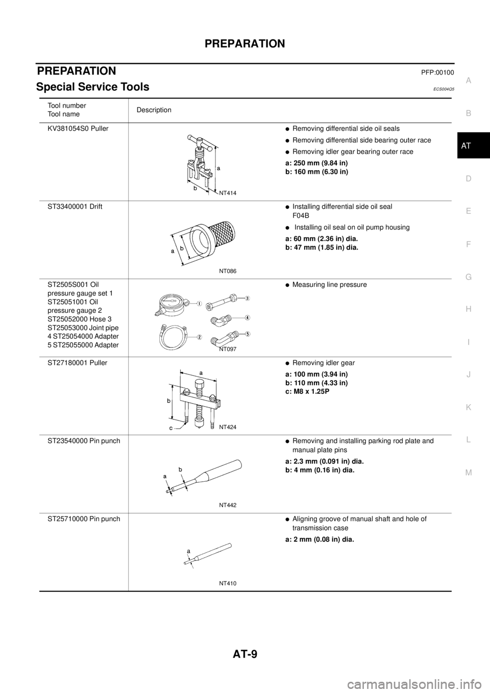
Tool number
To o l n a m eDescription
KV381054S0 Puller
lRemoving differential side oil seals
lRemoving differential side bearing outer race
lRemoving idler gear bearing outer race
a: 250 mm (9.84 in)
b: 160 mm (6.30 in)
ST33400001 Drift
lInstalling differential side oil seal
F04B
lInstalling oil seal on oil pump housing
a: 60 mm (2.36 in) dia.
b: 47 mm (1.85 in) dia.
ST2505S001 Oil
pressure gauge set 1
ST25051001 Oil
pressure gauge 2
ST25052000 Hose 3
ST25053000 Joint pipe
4 ST25054000 Adapter
5 ST25055000 Adapter
lMeasuring line pressure
ST27180001 Puller
lRemoving idler gear
a: 100 mm (3.94 in)
b: 110 mm (4.33 in)
c: M8 x 1.25P
ST23540000 Pin punch
lRemoving and installing parking rod plate and
manual plate pins
a: 2.3 mm (0.091 in) dia.
b: 4 mm (0.16 in) dia.
ST25710000 Pin punch
lAligning groove of manual shaft and hole of
transmission case
a: 2 mm (0.08 in) dia.
NT414
NT086
NT097
NT424
NT442
NT410
Page 17 of 3066
PREPARATION
AT-11
D
E
F
G
H
I
J
K
L
MA
B
AT
Commercial Service ToolsECS004Q6
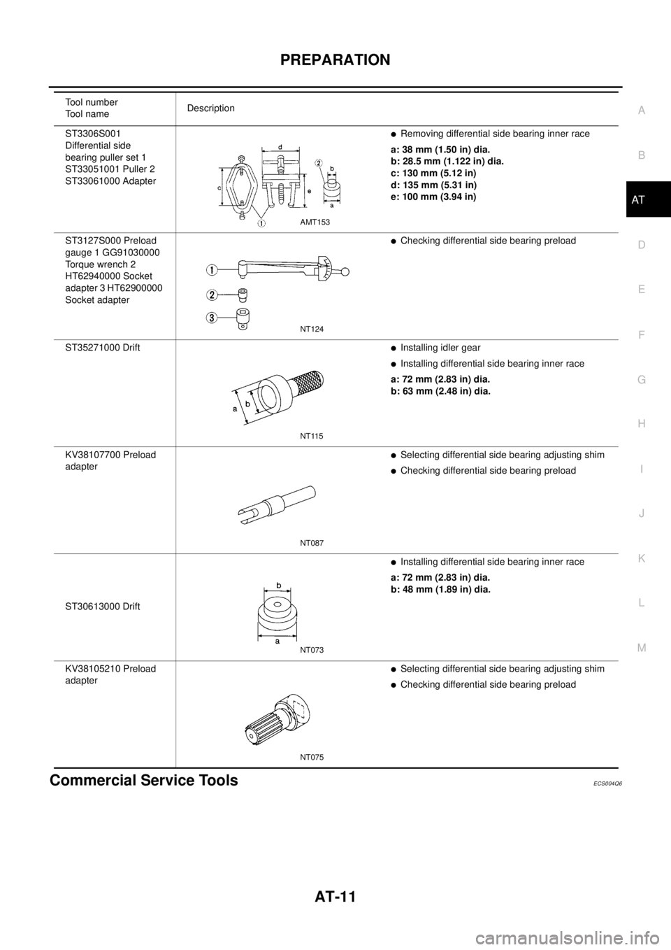
ST3306S001
Differential side
bearing puller set 1
ST33051001 Puller 2
ST33061000 AdapterlRemoving differential side bearing inner race
a: 38 mm (1.50 in) dia.
b: 28.5 mm (1.122 in) dia.
c: 130 mm (5.12 in)
d: 135 mm (5.31 in)
e: 100 mm (3.94 in)
ST3127S000 Preload
gauge 1 GG91030000
To r q u e w r e n c h 2
HT62940000 Socket
adapter 3 HT62900000
Socket adapter
lChecking differential side bearing preload
ST35271000 Drift
lInstalling idler gear
lInstalling differential side bearing inner race
a: 72 mm (2.83 in) dia.
b: 63 mm (2.48 in) dia.
KV38107700 Preload
adapter
lSelecting differential side bearing adjusting shim
lChecking differential side bearing preload
ST30613000 Drift
lInstalling differential side bearing inner race
a: 72 mm (2.83 in) dia.
b: 48 mm (1.89 in) dia.
KV38105210 Preload
adapter
lSelecting differential side bearing adjusting shim
lChecking differential side bearing preload Tool number
To o l n a m eDescription
AMT153
NT124
NT115
NT087
NT073
NT075
Page 47 of 3066
![NISSAN X-TRAIL 2003 Electronic User Guide ON BOARD DIAGNOSTIC SYSTEM DESCRIPTION
AT-41
[EURO-OBD]
D
E
F
G
H
I
J
K
L
MA
B
AT
Malfunction Indicator lamp (MIL)ECS004QL
1. The malfunction indicator lamp will light up when the ignition
switch is t](/img/5/57402/w960_57402-46.png "NISSAN X-TRAIL 2003 Electronic User Guide ON BOARD DIAGNOSTIC SYSTEM DESCRIPTION
AT-41
[EURO-OBD]
D
E
F
G
H
I
J
K
L
MA
B
AT
Malfunction Indicator lamp (MIL)ECS004QL
1. The malfunction indicator lamp will light up when the ignition
switch is t")
ON BOARD DIAGNOSTIC SYSTEM DESCRIPTION
AT-41
[EURO-OBD]
D
E
F
G
H
I
J
K
L
MA
B
AT
Malfunction Indicator lamp (MIL)ECS004QL
1. The malfunction indicator lamp will light up when the ignition
switch is turned ON without the engine running. This is for
checking the lamp.
lIf the malfunction indicator does not light up, refer to "",
“Warning Lamps”.
(Or see MIL & CONSULT-II in EC section. Refer toEC-48,
"Malfunction Indicator (MI)", “Description”, “Malfunction Indi-
cator lamp (MIL)” and "", “CONSULT-II”.)
2. When the engine is started, the malfunction indicator should go
off.
If the lamp remains on, the on board diagnostic system has
detected an emission-related (EURO-OBD) malfunction. For
detail, refer to "njec0029", “ON BOARD DIAGNOSTIC SYSTEM DESCRIPTION”.
CONSULT-IIECS0 04 QM
After performing “SELF-DIAGNOSTIC PROCEDURE (WITH CONSULT-II)”AT- 4 1 , "SELF-DIAGNOSTIC
PROCEDURE (WITH CONSULT-II)", place check marks for results on the “DIAGNOSTIC WORKSHEET”,
AT- 5 7 , "
DIAGNOSTIC WORKSHEET". Reference pages are provided following the items.
NOTICE:
1. The CONSULT-II electrically displays shift timing and lock-up timing (that is, operation timing of each sole-
noid).
Check for time difference between actual shift timing and the CONSULT-II display. If the difference is
noticeable, mechanical parts (except solenoids, sensors, etc.) may be malfunctioning. Check mechanical
parts using applicable diagnostic procedures.
2. Shift schedule (which implies gear position) displayed on CONSULT-II and that indicated in Service Man-
ual may differ slightly. This occurs because of the following reasons:
–Actual shift schedule has more or less tolerance or allowance,
–Shift schedule indicated in Service Manual refers to the point where shifts start, and
–Gear position displayed on CONSULT-II indicates the point where shifts are completed.
3. Shift solenoid valve “A” or “B” is displayed on CONSULT-II at the start of shifting. Gear position is dis-
played upon completion of shifting (which is computed by TCM).
4. Additional CONSULT-II information can be found in the Operation Manual supplied with the CONSULT-II
unit.
SELF-DIAGNOSTIC PROCEDURE (WITH CONSULT-II)
1. Turn on CONSULT-II and touch “ENGINE” for EURO-OBD
detected items or touch “A/T” for TCM self-diagnosis.
If A/T is not displayed, check TCM power supply and ground cir-
cuit. Refer toAT - 1 2 5 , "
TCM Terminals and Reference Value".If
result is NG, refer toPG-2, "
POWER SUPPLY ROUTING".
SAT652J
SAT014K
Page 62 of 3066
![NISSAN X-TRAIL 2003 Electronic User Guide AT-56
[EURO-OBD]
TROUBLE DIAGNOSIS — INTRODUCTION
TROUBLE DIAGNOSIS — INTRODUCTION
PFP:00000
IntroductionECS0 04 QO
The TCM receives a signal from the vehicle speed sensor, throttle
position senso](/img/5/57402/w960_57402-61.png "NISSAN X-TRAIL 2003 Electronic User Guide AT-56
[EURO-OBD]
TROUBLE DIAGNOSIS — INTRODUCTION
TROUBLE DIAGNOSIS — INTRODUCTION
PFP:00000
IntroductionECS0 04 QO
The TCM receives a signal from the vehicle speed sensor, throttle
position senso")
AT-56
[EURO-OBD]
TROUBLE DIAGNOSIS — INTRODUCTION
TROUBLE DIAGNOSIS — INTRODUCTION
PFP:00000
IntroductionECS0 04 QO
The TCM receives a signal from the vehicle speed sensor, throttle
position sensor or PNP switch and provides shift control or lock-up
control via A/T solenoid valves.
The TCM also communicates with the ECM by means of a signal
sent from sensing elements used with the EURO-OBD related parts
of the A/T system for malfunction-diagnostic purposes. The TCM is
capable of diagnosing malfunctioning parts while the ECM can store
malfunctions in its memory.
Input and output signals must always be correct and stable in the
operation of the A/T system. The A/T system must be in good oper-
ating condition and be free of valve seizure, solenoid valve malfunc-
tion, etc.
It is much more difficult to diagnose a problem that occurs intermit-
tently rather than continuously. Most intermittent problems are
caused by poor electric connections or improper wiring. In this case,
careful checking of suspected circuits may help prevent the replace-
ment of good parts.
A visual check only, may not find the cause of the problems. A road
test with CONSULT-II (or GST) or a circuit tester connected should
be performed. Follow the “Work Flow”. Refer toAT- 6 1 , "
Work Flow".
Before undertaking actual checks, take a few minutes to talk with a
customer who approaches with a driveability complaint. The cus-
tomer can supply good information about such problems, especially
intermittent ones. Find out what symptoms are present and under
what conditions they occur. A “Diagnostic Worksheet” like the exam-
ple (AT-57, "
DIAGNOSTIC WORKSHEET") should be used.
Start your diagnosis by looking for “conventional” problems first. This
will help troubleshoot driveability problems on an electronically con-
trolled engine vehicle.
Also check related Service bulletins for information.
SAT631IA
SAT632I
SEF234G
Page 63 of 3066
![NISSAN X-TRAIL 2003 Electronic User Guide TROUBLE DIAGNOSIS — INTRODUCTION
AT-57
[EURO-OBD]
D
E
F
G
H
I
J
K
L
MA
B
AT
DIAGNOSTIC WORKSHEET
Information from Customer
KEY POINTS
lWHAT..... Vehicle & A/T model
lWHEN..... Date, Frequencies
lWHE](/img/5/57402/w960_57402-62.png "NISSAN X-TRAIL 2003 Electronic User Guide TROUBLE DIAGNOSIS — INTRODUCTION
AT-57
[EURO-OBD]
D
E
F
G
H
I
J
K
L
MA
B
AT
DIAGNOSTIC WORKSHEET
Information from Customer
KEY POINTS
lWHAT..... Vehicle & A/T model
lWHEN..... Date, Frequencies
lWHE")
TROUBLE DIAGNOSIS — INTRODUCTION
AT-57
[EURO-OBD]
D
E
F
G
H
I
J
K
L
MA
B
AT
DIAGNOSTIC WORKSHEET
Information from Customer
KEY POINTS
lWHAT..... Vehicle & A/T model
lWHEN..... Date, Frequencies
lWHERE..... Road conditions
lHOW..... Operating conditions, Symptoms
Customer name MR/MS Model & Year VIN
Trans. model Engine Mileage
Incident Date Manuf. Date In Service Date
FrequencyoContinuousoIntermittent ( times a day)
SymptomsoVehicle does not move. (oAny positionoParticular position)
oNo up-shift (o1st®2ndo2nd®3rdo3rd®O/D)
oNo down-shift (oO/D®3rdo3rd®2ndo2nd®1st)
oLockup malfunction
oShift point too high or too low.
oShift shock or slip (oN®DoLockupoAny drive position)
oNoise or vibration
oNo kickdown
oNo pattern select
oOthers
()
O/D OFF indicator lamp Blinks for about 8 seconds.
oContinuously litoNot lit
Malfunction indicator lamp (MIL)oContinuously litoNot lit
Page 69 of 3066
![NISSAN X-TRAIL 2003 Electronic User Guide TROUBLE DIAGNOSIS — INTRODUCTION
AT-63
[EURO-OBD]
D
E
F
G
H
I
J
K
L
MA
B
AT
*1:AT- 5 7 , "Information from Customer"*2:AT- 5 8 , "Diagnostic Worksheet"*3:AT-7 , "ServiceNoticeorPrecau-
tions"
*4:AT-](/img/5/57402/w960_57402-68.png "NISSAN X-TRAIL 2003 Electronic User Guide TROUBLE DIAGNOSIS — INTRODUCTION
AT-63
[EURO-OBD]
D
E
F
G
H
I
J
K
L
MA
B
AT
*1:AT- 5 7 , \"Information from Customer\"*2:AT- 5 8 , \"Diagnostic Worksheet\"*3:AT-7 , \"ServiceNoticeorPrecau-
tions\"
*4:AT-")
TROUBLE DIAGNOSIS — INTRODUCTION
AT-63
[EURO-OBD]
D
E
F
G
H
I
J
K
L
MA
B
AT
*1:AT- 5 7 , "Information from Customer"*2:AT- 5 8 , "Diagnostic Worksheet"*3:AT-7 , "ServiceNoticeorPrecau-
tions"
*4:AT- 6 4 , "A/T Fluid Check"*5:AT- 6 5 , "Stall Test"andAT- 6 8 , "Line Pressure
Te s t"
*6:AT-6 9 , "Road Test"
*7:AT- 4 1 , "CONSULT-II"*8:AT- 3 7 , "ON BOARD DIAGNOSTIC SYSTEM
DESCRIPTION"
*9:AT-5 0 , "Diagnostic Procedure
Without CONSULT-II"
*10:AT- 1 3 0 , "DTC P0705 PARK/NEU-
TRAL POSITION (PNP) SWITCH"
*11:AT- 2 2 2 , "DTC VEHICLE SPEED SENSOR
MTR"andAT-226, "DTC CONTROL UNIT
(RAM), CONTROL UNIT (ROM)"toAT- 2 2 8 ,
"DTC CONTROL UNIT(EEPROM)"
*12:AT-2 3 2 , "1. O/D OFF Indicator
Lamp Does Not Come On"
*13:AT- 2 5 9 , "20. Vehicle Does Not Decel-
erate By Engine Brake"
*14:AT- 8 6 , "Symptom Chart"*15:AT-3 9 , "HOW TO ERASE DTC"
*16:AT- 1 3 1 , "DIAGNOSTIC TROUBLE
CODE (DTC) CONFIRMATION PRO-
CEDURE"
*17:AT- 2 2 2 , "DTC VEHICLE SPEED SENSOR
MTR"andAT-226, "DTC CONTROL UNIT
(RAM), CONTROL UNIT (ROM)"toAT- 2 2 8 ,
"DTC CONTROL UNIT(EEPROM)"
*18: EC-XX
Page 75 of 3066
![NISSAN X-TRAIL 2003 Electronic User Guide TROUBLE DIAGNOSIS — BASIC INSPECTION
AT-69
[EURO-OBD]
D
E
F
G
H
I
J
K
L
MA
B
AT
5. Start engine and measure line pressure at idle and stall speed.
lWhen measuring line pressure at stall speed, follo](/img/5/57402/w960_57402-74.png "NISSAN X-TRAIL 2003 Electronic User Guide TROUBLE DIAGNOSIS — BASIC INSPECTION
AT-69
[EURO-OBD]
D
E
F
G
H
I
J
K
L
MA
B
AT
5. Start engine and measure line pressure at idle and stall speed.
lWhen measuring line pressure at stall speed, follo")
TROUBLE DIAGNOSIS — BASIC INSPECTION
AT-69
[EURO-OBD]
D
E
F
G
H
I
J
K
L
MA
B
AT
5. Start engine and measure line pressure at idle and stall speed.
lWhen measuring line pressure at stall speed, follow the
stall test procedure.
Line pressure: Refer toAT-563, "
SERVICE DATA AND SPECIFI-
CATIONS (SDS)".
JUDGEMENT OF LINE PRESSURE TEST
Road TestECS004QT
DESCRIPTION
lThe purpose of the test is to determine overall performance of A/
T and analyze causes of problems.
lThe road test consists of the following three parts:
1. Check before engine is started
2. Check at idle
SAT493G
Judgement Suspected parts
At idleLine pressure is low in all positions.
lOil pump wear
lControl piston damage
lPressure regulator valve or plug sticking
lSpring for pressure regulator valve damaged
lFluid pressure leakage between oil strainer and pressure regulator valve
lClogged strainer
Line pressure is low in particular posi-
tion.
lFluid pressure leakage between manual valve and particular clutch
lFor example, line pressure is:
-Low in “R” and “1” positions, but
-Normal in “D” and “2” positions.
Therefore, fluid leakage exists at or around low and reverse brake circuit.
Refer to “CLUTCH AND BAND CHART”,AT-19, "
CLUTCH AND BAND
CHART".
Line pressure is high.
lMaladjustment of throttle position sensor
lA/T fluid temperature sensor damaged
lLine pressure solenoid valve sticking
lShort circuit of line pressure solenoid valve circuit
lPressure modifier valve sticking
lPressure regulator valve or plug sticking
lOpen in dropping resistor circuit
At stall
speedLine pressure is low.
lMaladjustment of throttle position sensor
lLine pressure solenoid valve sticking
lShort circuit of line pressure solenoid valve circuit
lPressure regulator valve or plug sticking
lPressure modifier valve sticking
lPilot valve sticking
SAT786A
Page 190 of 3066
![NISSAN X-TRAIL 2003 Electronic User Guide AT-184
[EURO-OBD]
DTC P0740 TORQUE CONVERTER CLUTCH SOLENOID VALVE
Diagnostic Procedure
ECS004RS
1.CHECK VALVE RESISTANCE
1. Turn ignition switch to “OFF” position.
2. Disconnect terminal cord ass](/img/5/57402/w960_57402-189.png "NISSAN X-TRAIL 2003 Electronic User Guide AT-184
[EURO-OBD]
DTC P0740 TORQUE CONVERTER CLUTCH SOLENOID VALVE
Diagnostic Procedure
ECS004RS
1.CHECK VALVE RESISTANCE
1. Turn ignition switch to “OFF” position.
2. Disconnect terminal cord ass")
AT-184
[EURO-OBD]
DTC P0740 TORQUE CONVERTER CLUTCH SOLENOID VALVE
Diagnostic Procedure
ECS004RS
1.CHECK VALVE RESISTANCE
1. Turn ignition switch to “OFF” position.
2. Disconnect terminal cord assembly connector in engine compartment.
3. Check resistance between terminal 5 and ground.
OK or NG
OK >> GO TO 2
NG >> 1. Remove oil pan. Refer toAT-454, "
ON-VEHICLE
SERVICE".
2. Check the following items:
–Torque converter clutch solenoid valve
Refer to “Component Inspection”,AT-185, "
Compo-
nent Inspection".
–Harness of terminal cord assembly for short or open
2.CHECK POWER SOURCE CIRCUIT
1. Turn ignition switch to “OFF” position.
2. Disconnect TCM harness connector.
3. Check continuity between terminal 5 and TCM harness connector terminal 3.
If OK, check harness for short to ground and short to power.
4. Reinstall any part removed.
OK or NG
OK >> GO TO 3
NG >> Repair open circuit or short to ground or short to power
in harness or connectors.
3.CHECK DTC
Perform Diagnostic Trouble Code (DTC) confirmation procedure,AT- 1 8 1 , "
DIAGNOSTIC TROUBLE CODE
(DTC) CONFIRMATION PROCEDURE".
OK or NG
OK >>INSPECTION END
NG >> 1. Perform TCM input/output signal inspection.
2. If NG, recheck TCM pin terminals for damage or loose connection with harness connector. Resistance : 5 - 20W
SCIA0731E
Continuity should exist.
SCIA0732E
Page 244 of 3066
![NISSAN X-TRAIL 2003 Electronic User Guide AT-238
[EURO-OBD]
TROUBLE DIAGNOSES FOR SYMPTOMS
2.CHECK STALL TEST
Check stall revolution with selector lever in “1” and “R” positions.
Refer toAT-65, "
Stall Te st".
OK or NG
OK >> GOTO3
OK](/img/5/57402/w960_57402-243.png "NISSAN X-TRAIL 2003 Electronic User Guide AT-238
[EURO-OBD]
TROUBLE DIAGNOSES FOR SYMPTOMS
2.CHECK STALL TEST
Check stall revolution with selector lever in “1” and “R” positions.
Refer toAT-65, \"
Stall Te st\".
OK or NG
OK >> GOTO3
OK")
AT-238
[EURO-OBD]
TROUBLE DIAGNOSES FOR SYMPTOMS
2.CHECK STALL TEST
Check stall revolution with selector lever in “1” and “R” positions.
Refer toAT-65, "
Stall Te st".
OK or NG
OK >> GOTO3
OK in “1” position, NG in “R” position>>1.Remove control valve
assembly. Refer to “ON-VEHICLE SERVICE”,AT-
453, "Installation".
2. Check the following items:
–Valves to control line pressure (Pressure regulator
valve, pressure modifier valve, pilot valve and pilot fil-
ter)
–Line pressure solenoid valve (AT-436, "LINE PRES-
SURE SOLENOID VALVE": Except for Euro-OBDAT-186, "DTC P0745 LINE PRESSURE
SOLENOID VALVE": Euro-OBD)
3. Disassemble A/T.
4. Check the following items:
–Oil pump assembly
–Torque converter
–Reverse clutch assembly
–High clutch assembly
–Low & reverse brake assembly
–Low one-way clutch
NG in both “1” and “R” positions>>GOTO6
3.CHECK LINE PRESSURE
Check line pressure at idle with selector lever in “R” position. Refer
to “Line Pressure Test”,AT-68, "
Line Pressure Test".
OK or NG
OK >> GOTO4
NG >> 1. Remove control valve assembly. Refer to “ON-VEHI-
CLE SERVICE”,AT-453, "
Installation".
2. Check the following items:
–Valves to control line pressure (Pressure regulator
valve, pressure modifier valve, pilot valve and pilot fil-
ter)
–Line pressure solenoid valve (AT-436, "LINE PRES-
SURE SOLENOID VALVE": Except for Euro-OBD/AT-186, "DTC P0745 LINE PRESSURE
SOLENOID VALVE": Euro-OBD)
3. Disassemble A/T.
4. Check the following item:
–Oil pump assembly
SAT493G
SAT494G
Page 245 of 3066
![NISSAN X-TRAIL 2003 Electronic User Guide TROUBLE DIAGNOSES FOR SYMPTOMS
AT-239
[EURO-OBD]
D
E
F
G
H
I
J
K
L
MA
B
AT
4.CHECKA/TFLUIDCONDITION
1. Remove oil pan.
2. Check A/T fluid condition.
OK or NG
OK >> GOTO5
NG >> GOTO6
5.CHECK SYMPTOM
Ch](/img/5/57402/w960_57402-244.png "NISSAN X-TRAIL 2003 Electronic User Guide TROUBLE DIAGNOSES FOR SYMPTOMS
AT-239
[EURO-OBD]
D
E
F
G
H
I
J
K
L
MA
B
AT
4.CHECKA/TFLUIDCONDITION
1. Remove oil pan.
2. Check A/T fluid condition.
OK or NG
OK >> GOTO5
NG >> GOTO6
5.CHECK SYMPTOM
Ch")
TROUBLE DIAGNOSES FOR SYMPTOMS
AT-239
[EURO-OBD]
D
E
F
G
H
I
J
K
L
MA
B
AT
4.CHECKA/TFLUIDCONDITION
1. Remove oil pan.
2. Check A/T fluid condition.
OK or NG
OK >> GOTO5
NG >> GOTO6
5.CHECK SYMPTOM
Check again.
OK or NG
OK >>INSPECTION END
NG >> 1. Perform TCM input/output signal inspection.
2. If NG, recheck TCM pin terminals for damage or loose connection with harness connector.
6.DETECT MALFUNCTIONING ITEM
1. Remove control valve assembly. Refer to “ON-VEHICLE SERVICE”,AT-453, "
Installation".
2. Check the following items:
–Valves to control line pressure (Pressure regulator valve, pressure modifier valve, pilot valve and pilot fil-
ter)
–Line pressure solenoid valve (AT- 4 3 6 , "LINE PRESSURE SOLENOID VALVE": Except for Euro-OBD/AT-
186, "DTC P0745 LINE PRESSURE SOLENOID VALVE":Euro-OBD)
3. Disassemble A/T.
4. Check the following items:
–Oil pump assembly
–Torque converter
–Reverse clutch assembly
–High clutch assembly
–Low & reverse brake assembly
–Low one-way clutch
OK or NG
OK >> GOTO5
NG >> Repair or replace damaged parts.
SAT171B