stop start NISSAN X-TRAIL 2003 Electronic User Guide
[x] Cancel search | Manufacturer: NISSAN, Model Year: 2003, Model line: X-TRAIL, Model: NISSAN X-TRAIL 2003Pages: 3066, PDF Size: 51.47 MB
Page 454 of 3066
![NISSAN X-TRAIL 2003 Electronic User Guide AT-448
[ALL]
A/T SHIFT LOCK SYSTEM
Diagnostic Procedure
ECS00408
SYMPTOM 1:
lSelector lever cannot be moved from “P” position with key in ON position and brake pedal
applied.
lSelector lever can b NISSAN X-TRAIL 2003 Electronic User Guide AT-448
[ALL]
A/T SHIFT LOCK SYSTEM
Diagnostic Procedure
ECS00408
SYMPTOM 1:
lSelector lever cannot be moved from “P” position with key in ON position and brake pedal
applied.
lSelector lever can b](/img/5/57402/w960_57402-453.png)
AT-448
[ALL]
A/T SHIFT LOCK SYSTEM
Diagnostic Procedure
ECS00408
SYMPTOM 1:
lSelector lever cannot be moved from “P” position with key in ON position and brake pedal
applied.
lSelector lever can be moved from “P” position with key in ON position and brake pedal released.
lSelector lever can be moved from “P” position when key is removed from key cylinder.
SYMPTOM 2:
Ignition key cannot be removed when selector lever is set to “P” position. It can be removed when
selector lever is set to any position except “P”.
1.CHECKKEYINTERLOCKCABLE
Check key interlock cable for damage.
OK or NG
OK >> GO TO 2
NG >> Repair key interlock cable. Refer toAT - 4 5 2 , "
KEY INTERLOCK CABLE".
2.CHECK SELECTOR LEVER POSITION
Check selector lever position for damage.
OK or NG
OK >> GO TO 3
NG >> Check selector lever. Refer toAT - 4 5 6 , "
Park/Neutral Position (PNP) Switch Adjustment".
3.CHECK POWER SOURCE
1. Turn ignition switch to “ON” position.
(Do not start engine.)
2. Check voltage between stop lamp switch harness terminal 1 and ground.
OK or NG
OK >> GO TO 4
NG >> Check the following items:
1. Harness for short or open between battery and stop
lamp switch harness terminal 1
2. Fuse
3. Ignition switch (Refer toPG-2, "
POWER SUPPLY
ROUTING".) Voltage : Battery voltageSCIA0782E
Page 455 of 3066
![NISSAN X-TRAIL 2003 Electronic User Guide A/T SHIFT LOCK SYSTEM
AT-449
[ALL]
D
E
F
G
H
I
J
K
L
MA
B
AT
4.CHECK INPUT SIGNAL (A/T DEVICE)
Turn ignition switch to “ON” position.
(Do not start engine.)
lCheck voltage between A/T device harne NISSAN X-TRAIL 2003 Electronic User Guide A/T SHIFT LOCK SYSTEM
AT-449
[ALL]
D
E
F
G
H
I
J
K
L
MA
B
AT
4.CHECK INPUT SIGNAL (A/T DEVICE)
Turn ignition switch to “ON” position.
(Do not start engine.)
lCheck voltage between A/T device harne](/img/5/57402/w960_57402-454.png)
A/T SHIFT LOCK SYSTEM
AT-449
[ALL]
D
E
F
G
H
I
J
K
L
MA
B
AT
4.CHECK INPUT SIGNAL (A/T DEVICE)
Turn ignition switch to “ON” position.
(Do not start engine.)
lCheck voltage between A/T device harness terminal 7 and ground.
OK or NG
OK >> GO TO 5
NG >> Check the following items:
1. Harness for short and open between battery and stop
lamp switch harness connector 1.
2. Harness for short or open between stop lamp switch harness connector 2 and A/T device har-
ness connector 7.
3. Fuse
4. Stop lamp switch (Refer toAT- 4 5 0 , "
A/T DEVICE CHECK".)
5.CHECK GROUND CIRCUIT
1. Turn ignition switch to “OFF” position.
2. Disconnect A/T device harness connector.
3. Check continuity between A/T device harness terminal 6 and ground.
If OK, check harness for short to ground and short to power.
OK or NG
OK >> GO TO 6
NG >> Repair open circuit or short to ground or short to power
in harness or connectors. Voltage:
Brake pedal depressd:
Battery voltage
Brake pedal released:
0V
SCIA0783E
Continuity should exist.
SCIA0784E
Page 599 of 3066
LUBRICANT
ATC-21
C
D
E
F
G
H
I
K
L
MA
B
AT C
LUBRICANTPFP:KLG00
Maintenance of Lubricant Quantity in CompressorEJS000TH
The lubricant in the compressor circulates through the system with the refrigerant. Add lubricant to compres-
sor when replacing any component or after a large gas leakage occurred. It is important to maintain the speci-
fied amount.
If lubricant quantity is not maintained properly, the following malfunctions may result:
lLack of lubricant: May lead to a seized compressor
lExcessive lubricant: Inadequate cooling (thermal exchange interference)
LUBRICANT
LUBRICANT RETURN OPERATION
Adjust the lubricant quantity according to the test group shown below.
1.CHECK LUBRICANT RETURN OPERATION
Can lubricant return operation be performed?
lA/C system works properly.
lThere is no evidence of a large amount of lubricant leakage.
Ye s o r N o
Yes >>GOTO2.
No >> GO TO 3.
2.PERFORM LUBRICANT RETURN OPERATION, PROCEEDING AS FOLLOWS:
1. Start engine, and set the following conditions:
–Test condition
Engine speed: Idling to 1,200 rpm
A/C or AUTO switch: ON
Blower speed: Max. position
Temp. control: Optional [Set so that intake air temperature is 25 to 30°C (77 to 86°F).]
Intake position: Recirculation (REC)
2. Perform lubricant return operation for about 10 minutes.
3. Stop engine.
CAUTION:
If excessive lubricant leakage is noted, do not perform the lubricant return operation.
>> GO TO 3.
3.CHECK COMPRESSOR
Should the compressor be replaced?
Ye s o r N o
Ye s > > G o t oAT C - 2 2 , "LUBRICANT ADJUSTING PROCEDURE FOR COMPRESSOR REPLACE-
MENT".
No >> GO TO 4.With gasoline engine
(CWV-615M Compressor)With diesel engine
(DKV-11G Compressor)
Name Nissan A/C System Oil Type S Nissan A/C System Oil Type R
Part number KLH00-PAGS0 KLH00-PAGR0
Page 603 of 3066
AIR CONDITIONER CONTROL
ATC-25
C
D
E
F
G
H
I
K
L
MA
B
AT C
TRANSMISSION DATA AND TRANSMISSION ORDER
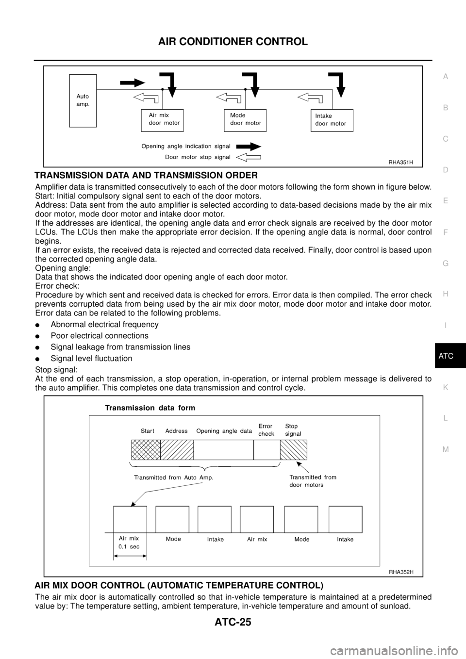
Amplifier data is transmitted consecutively to each of the door motors following the form shown in figure below.
Start: Initial compulsory signal sent to each of the door motors.
Address: Data sent from the auto amplifier is selected according to data-based decisions made by the air mix
door motor, mode door motor and intake door motor.
If the addresses are identical, the opening angle data and error check signals are received by the door motor
LCUs. The LCUs then make the appropriate error decision. If the opening angle data is normal, door control
begins.
If an error exists, the received data is rejected and corrected data received. Finally, door control is based upon
the corrected opening angle data.
Opening angle:
Data that shows the indicated door opening angle of each door motor.
Error check:
Procedure by which sent and received data is checked for errors. Error data is then compiled. The error check
prevents corrupted data from being used by the air mix door motor, mode door motor and intake door motor.
Error data can be related to the following problems.
lAbnormal electrical frequency
lPoor electrical connections
lSignal leakage from transmission lines
lSignal level fluctuation
Stop signal:
At the end of each transmission, a stop operation, in-operation, or internal problem message is delivered to
the auto amplifier. This completes one data transmission and control cycle.
AIR MIX DOOR CONTROL (AUTOMATIC TEMPERATURE CONTROL)
The air mix door is automatically controlled so that in-vehicle temperature is maintained at a predetermined
value by: The temperature setting, ambient temperature, in-vehicle temperature and amount of sunload.
RHA351H
RHA352H
Page 666 of 3066
ATC-88
TROUBLE DIAGNOSIS
Both High- and Low-pressure Sides are Too Low.
Low-pressure Side Sometimes Becomes Negative.
Gauge indication Refrigerant cycle Probable cause Corrective action
Both high- and low-pressure sides
are too low.
lThere is a big temperature
difference between receiver
drier outlet and inlet. Outlet
temperature is extremely
low.
lLiquid tank inlet and expan-
sion valve are frosted.Liquid tank inside is slightly
clogged.
lReplace desiccant assem-
bly.
lCheck lubricant for contami-
nation.
lTemperature of expansion
valve inlet is extremely low
as compared with areas
near liquid tank.
lExpansion valve inlet may
be frosted.
lTemperature difference
occurs somewhere in high-
pressure sideHigh-pressure pipe located
between receiver drier and
expansion valve is clogged.
lCheck and repair malfunc-
tioning parts.
lCheck lubricant for contami-
nation.
Expansion valve and liquid
tank are warm or only cool
when touched.Low refrigerant charge
¯
Leaking fittings or componentsCheck refrigerant for leaks.
Refer to Checking Refrigerant
Leaks,AT C - 1 4 0
.
There is a big temperature dif-
ference between expansion
valve inlet and outlet while the
valve itself is frosted.Expansion valve closes a little
compared with the specifica-
tion.
¯
1. Improper expansion valve
adjustment
2. Malfunctioning thermal
valve
3. Outlet and inlet may be
clogged.
lRemove foreign particles by
using compressed air.
lCheck lubricant for contami-
nation.
An area of the low-pressure
pipe is colder than areas near
the evaporator outlet.Low-pressure pipe is clogged
or crushed.
lCheck and repair malfunc-
tioning parts.
lCheck lubricant for contami-
nation.
Air flow volume is not enough
or is too low.Evaporator is frozen.
lCheck intake sensor circuit.
lReplace compressor.
AC353A
Gauge indication Refrigerant cycle Probable cause Corrective action
Low-pressure side sometimes
becomes negative.
lAir conditioning system
does not function and does
not cyclically cool the com-
partment air.
lThe system constantly func-
tions for a certain period of
time after compressor is
stopped and restarted.Refrigerant does not dis-
charge cyclically.
¯
Moisture is frozen at expan-
sion valve outlet and inlet.
¯
Water is mixed with refriger-
ant.
lDrain water from refrigerant
or replace refrigerant.
lReplace desiccant assy.
AC354A
Page 721 of 3066
REFRIGERANT LINES
ATC-143
C
D
E
F
G
H
I
K
L
MA
B
AT C
Check all around the service valves. Ensure service valve caps are secured on the service valves (to pre-
vent leaks).
NOTE:
After removing A/C manifold gauge set from service valves, wipe any residue from valves to prevent any
false readings by leak detector.
Cooling unit (Evaporator)
With engine OFF, turn blower fan on "High" for at least 15 seconds to dissipate any refrigerant trace in the
cooling unit. Wait a minimum of 10 minutes accumulation time (refer to the manufacturer's recommended
procedure for actual wait time) before inserting the leak detector probe into the drain hose.
Keep the probe inserted for at least 10 seconds. Use caution not to contaminate the probe tip with water
or dirt that may be in the drain hose.
5. If a leak detector detects a leak, verify at least once by blowing compressed air into area of suspected
leak, then repeat check as outlined above.
6. Do not stop when one leak is found. Continue to check for additional leaks at all system components.
If no leaks are found, perform steps 7 - 10.
7. Start engine.
8. Set the heater A/C control as follows;
a. A/C switch: ON
b. Face mode
c. Intake position: Recirculation
d. Max cold temperature
e. Fan speed: High
9. Run engine at 1,500 rpm for at least 2 minutes.
10. Turn engine off and perform leak check again following steps 4 through 6 above.
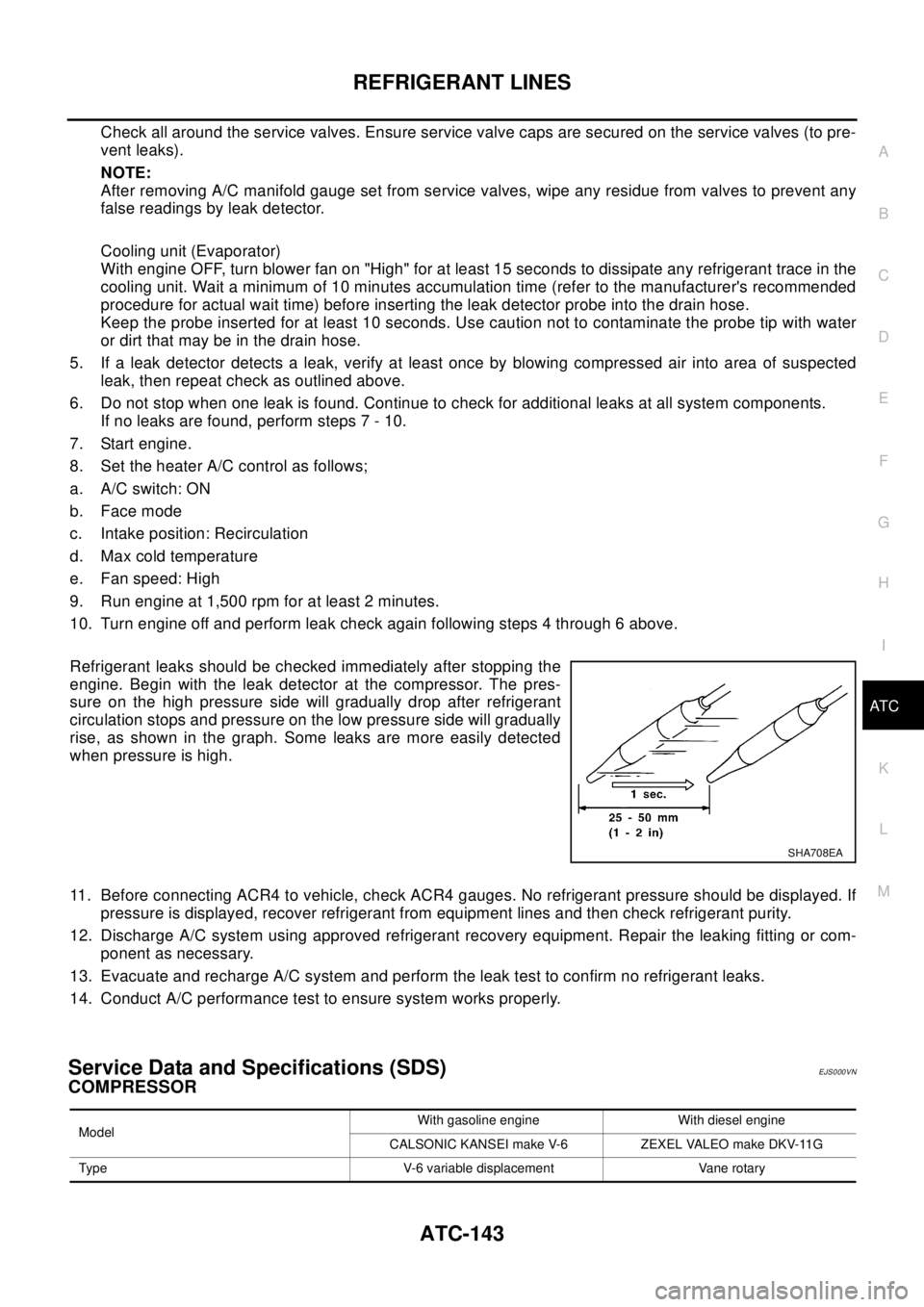
Refrigerant leaks should be checked immediately after stopping the
engine. Begin with the leak detector at the compressor. The pres-
sure on the high pressure side will gradually drop after refrigerant
circulation stops and pressure on the low pressure side will gradually
rise, as shown in the graph. Some leaks are more easily detected
when pressure is high.
11. Before connecting ACR4 to vehicle, check ACR4 gauges. No refrigerant pressure should be displayed. If
pressure is displayed, recover refrigerant from equipment lines and then check refrigerant purity.
12. Discharge A/C system using approved refrigerant recovery equipment. Repair the leaking fitting or com-
ponent as necessary.
13. Evacuate and recharge A/C system and perform the leak test to confirm no refrigerant leaks.
14. Conduct A/C performance test to ensure system works properly.
Service Data and Specifications (SDS)EJS000VN
COMPRESSOR
SHA708EA
ModelWith gasoline engine With diesel engine
CALSONIC KANSEI make V-6 ZEXEL VALEO make DKV-11G
Type V-6 variable displacement Vane rotary
Page 841 of 3066
BRAKE PEDAL
BR-7
C
D
E
G
H
I
J
K
L
MA
B
BR
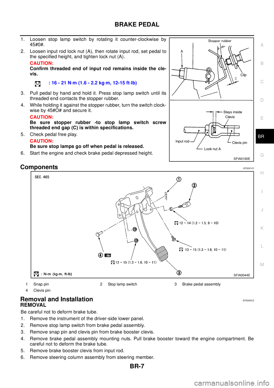
1. Loosen stop lamp switch by rotating it counter-clockwise by
45#0#.
2. Loosen input rod lock nut (A), then rotate input rod, set pedal to
the specified height, and tighten lock nut (A).
CAUTION:
Confirm threaded end of input rod remains inside the cle-
vis.
3. Pull pedal by hand and hold it. Press stop lamp switch until its
threaded end contacts the stopper rubber.
4. While holding it against the stopper rubber, turn the switch clock-
wise by 45#O# and secure it.
CAUTION:
Be sure stopper rubber -to stop lamp switch screw
threaded end gap (C) is within specifications.
5. Check pedal free play.
CAUTION:
Be sure stop lamps go off when pedal is released.
6. Start the engine and check brake pedal depressed height.
ComponentsEF S0 01 CI
Removal and InstallationEFS000C2
REMOVAL
Be careful not to deform brake tube.
1. Remove the instrument of the driver-side lower panel.
2. Remove stop lamp switch from brake pedal assembly.
3. Remove snap pin and clevis pin from brake booster clevis.
4. Remove brake pedal assembly mounting nuts. Pull brake booster toward the engine compartment. Be
careful not to deform the brake tube.
5. Remove brake booster clevis from input rod.
6. Remove steering column assembly from steering member.: 16 - 21 N·m (1.6 - 2.2 kg·m, 12-15 ft·lb)
SFIA0160E
SFIA0044E
1 Snap pin 2 Stop lamp switch 3 Brake pedal assembly
4 Clevis pin
Page 851 of 3066
BRAKE BOOSTER
BR-17
C
D
E
G
H
I
J
K
L
MA
B
BR
BRAKE BOOSTERPFP:47200
On-Vehicle Inspection and ServiceEFS000CC
FUNCTION INSPECTION
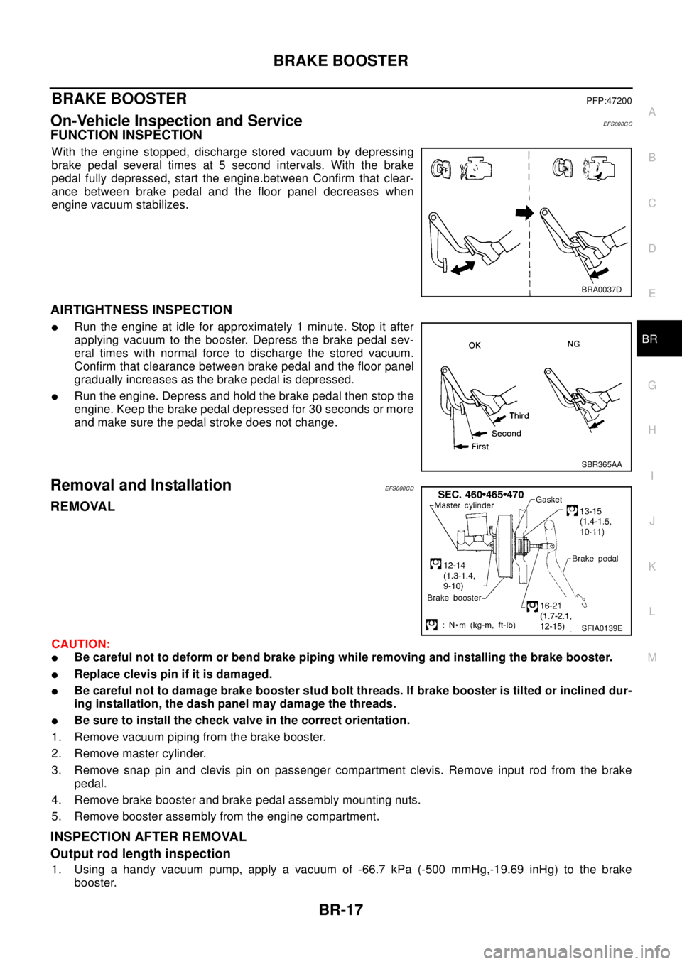
With the engine stopped, discharge stored vacuum by depressing
brake pedal several times at 5 second intervals. With the brake
pedal fully depressed, start the engine.between Confirm that clear-
ance between brake pedal and the floor panel decreases when
engine vacuum stabilizes.
AIRTIGHTNESS INSPECTION
lRun the engine at idle for approximately 1 minute. Stop it after
applying vacuum to the booster. Depress the brake pedal sev-
eral times with normal force to discharge the stored vacuum.
Confirm that clearance between brake pedal and the floor panel
gradually increases as the brake pedal is depressed.
lRun the engine. Depress and hold the brake pedal then stop the
engine. Keep the brake pedal depressed for 30 seconds or more
and make sure the pedal stroke does not change.
Removal and InstallationEFS000CD
REMOVAL
CAUTION:
lBe careful not to deform or bend brake piping while removing and installing the brake booster.
lReplace clevis pin if it is damaged.
lBe careful not to damage brake booster stud bolt threads. If brake booster is tilted or inclined dur-
ing installation, the dash panel may damage the threads.
lBe sure to install the check valve in the correct orientation.
1. Remove vacuum piping from the brake booster.
2. Remove master cylinder.
3. Remove snap pin and clevis pin on passenger compartment clevis. Remove input rod from the brake
pedal.
4. Remove brake booster and brake pedal assembly mounting nuts.
5. Remove booster assembly from the engine compartment.
INSPECTION AFTER REMOVAL
Output rod length inspection
1. Using a handy vacuum pump, apply a vacuum of -66.7 kPa (-500 mmHg,-19.69 inHg) to the brake
booster.
BRA0037D
SBR365AA
SFIA0139E
Page 872 of 3066
![NISSAN X-TRAIL 2003 Electronic User Guide BRC-4
[4WD/ABS]
PRECAUTIONS
[4WD/ABS]PRECAUTIONSPFP:00001
Precautions for brake systemEFS001B6
lRecommended fluid is brake fluid “DOT 3 ”or “DOT 4”.
lNever reuse drained brake fluid.
lBe caref NISSAN X-TRAIL 2003 Electronic User Guide BRC-4
[4WD/ABS]
PRECAUTIONS
[4WD/ABS]PRECAUTIONSPFP:00001
Precautions for brake systemEFS001B6
lRecommended fluid is brake fluid “DOT 3 ”or “DOT 4”.
lNever reuse drained brake fluid.
lBe caref](/img/5/57402/w960_57402-871.png)
BRC-4
[4WD/ABS]
PRECAUTIONS
[4WD/ABS]PRECAUTIONSPFP:00001
Precautions for brake systemEFS001B6
lRecommended fluid is brake fluid “DOT 3 ”or “DOT 4”.
lNever reuse drained brake fluid.
lBe careful not to splash brake fluid on painted areas.
lTo clean or wash all parts of master cylinder, disc brake caliper and wheel cylinder, use clean brake fluid.
lNever use mineral oils such as gasoline or kerosene. They will ruin rubber parts of the hydraulic system.
lUse flare nut wrench when removing and installing brake tube.
lAlways torque brake lines when installing.
lBurnish the brake contact surfaces after refinishing or replacing
drums or rotors, after replacing pads or linings, or if a soft pedal
occurs at very low mileage. Refer toBR-10, "
Brake Burnishing
Procedure".
lBefore working, turn OFF ignition switch. Disconnect connectors
for ABS actuator and control module or battery terminals.
WAR NIN G:
lClean brake pads and shoes with a waste cloth, then wipe
with a dust collector.
Precautions for brake controlEFS001B7
lIf malfunction is indicated by 4WD warning lamp and/or ABS warning lamp, collect necessary information
from customer (what symptoms are present under what conditions). Find out possible causes before start-
ing service. Besides electrical system inspection, check operation of ABS actuator.
lIf malfunction is detected, proceed to trouble diagnosis after checking tire pressure and tire wear.
lStopping distance or steering stability may be deteriorated by the following conditions. Tire size and type
are in improper combination. Brake pads are not Nissan genuine parts.
lFitting tires of different size on vehicle can be cause of longitudinal vibration. Always use tires of the same
size and brand. Exchange front and rear tires on the following conditions: Longitudinal vibration occurs in
vehicle with tires of the same size and brand. After replacement, perform trouble diagnosis. 1580|None
l4WD/ABS function may have a failure or error under following condition: There is radio, antenna, or
antenna lead-in wire (including wiring) near control module.
lIf aftermarket parts (e.g. Car stereo equipment, CD player) have been installed, check electrical har-
nesses for pinches, open, and improper wiring.
SBR686C
Page 874 of 3066
![NISSAN X-TRAIL 2003 Electronic User Guide BRC-6
[4WD/ABS]
ALL MODE 4X4 SYSTEM
ALL MODE 4X4 SYSTEM
PFP:47850
System DescriptionEFS001CJ
ABS FUNCTION
lDuring ABS operation, brake pedal lightly vibrates and its mechanical noise may be heard. Thi NISSAN X-TRAIL 2003 Electronic User Guide BRC-6
[4WD/ABS]
ALL MODE 4X4 SYSTEM
ALL MODE 4X4 SYSTEM
PFP:47850
System DescriptionEFS001CJ
ABS FUNCTION
lDuring ABS operation, brake pedal lightly vibrates and its mechanical noise may be heard. Thi](/img/5/57402/w960_57402-873.png)
BRC-6
[4WD/ABS]
ALL MODE 4X4 SYSTEM
ALL MODE 4X4 SYSTEM
PFP:47850
System DescriptionEFS001CJ
ABS FUNCTION
lDuring ABS operation, brake pedal lightly vibrates and its mechanical noise may be heard. This is a nor-
mal condition.
lWhen starting engine, or just after starting vehicle, brake pedal may vibrate. Also motor operating noise
may be heard from engine compartment. This is a normal status of operation check.
lWhen vehicle drives on rough, gravel, or snowy (fresh deep snow) road, the following conditions occur.
Stopping distance may be longer than that of vehicles without ABS.
4WD FUNCTION
lElectronically controlled 4WD is controlled by the same control module as that for ABS (4WD/ABS control
unit). 4WD/ABS control unit controls both electronically-controlled 4WD and ABS, based on input signals
from several sensors.
lIf electrical system-related malfunction occurred in 4WD/ABS system, control unit illuminates the following
lamps: 4WD warning lamp and/or ABS warning lamp on meter control unit assembly. This notifies driver of
malfunction. At the same time, control unit indicates malfunctioning part detected by self-diagnosis with
flashing pattern of LED. Indication on electronic system diagnosis tester (CONSULT) corresponds to this
flashing pattern as shown below.
Control System DiagramEFS001CK
Self-diagnostic test mode Remarks
Result of self-diagnosis Conformable to 4WD/ABS
Data monitor Conformable to 4WD/ABS
Active testChecks ABS solenoid valve ON/OFF, ABS motor ON/OFF, 4WD sole-
noid
Control unit part No. 4WD/ABS control unit
SFIA0350E