wheel alignment NISSAN X-TRAIL 2003 Electronic Repair Manual
[x] Cancel search | Manufacturer: NISSAN, Model Year: 2003, Model line: X-TRAIL, Model: NISSAN X-TRAIL 2003Pages: 3066, PDF Size: 51.47 MB
Page 922 of 3066
![NISSAN X-TRAIL 2003 Electronic Repair Manual BRC-54
[ESP/TCS/ABS]
ON-VEHICLE SERVICE
ON-VEHICLE SERVICE
PFP:00000
Adjustment of Neutral Position of Steering Angle SensorEFS0019R
lAfter removing/installing or replacing the ESP/TCS/ABS control uni NISSAN X-TRAIL 2003 Electronic Repair Manual BRC-54
[ESP/TCS/ABS]
ON-VEHICLE SERVICE
ON-VEHICLE SERVICE
PFP:00000
Adjustment of Neutral Position of Steering Angle SensorEFS0019R
lAfter removing/installing or replacing the ESP/TCS/ABS control uni](/img/5/57402/w960_57402-921.png)
BRC-54
[ESP/TCS/ABS]
ON-VEHICLE SERVICE
ON-VEHICLE SERVICE
PFP:00000
Adjustment of Neutral Position of Steering Angle SensorEFS0019R
lAfter removing/installing or replacing the ESP/TCS/ABS control unit, steering angle sensor, steering com-
ponents, suspension components, and tires, or after adjusting the wheel alignment, make sure to adjust
the neutral position of the steering angle sensor before running the vehicle.
CAUTION:
To adjust the neutral position of the steering angle sensor, make sure to use CONSULT-II.
(Adjustment cannot be done other than CONSULT-II.)
1. Stop the vehicle with the front wheels in the straight-ahead position.
2. Connect CONSULT-II to data link connector on the vehicle, and
turn the ignition switch to ON position (engine not running).
3. Touch “START”, “ABS”, “WORK SUPPORT” and “ST ANGLE
SENSOR ADJUSTMENT” on the CONSULT-II screen in this
order.
PBIB0196E
SFIA0364E
SFIA0365E
SFIA0370E
Page 956 of 3066
![NISSAN X-TRAIL 2003 Electronic Repair Manual BRC-88
[ESP/TCS/ABS]
TROUBLE DIAGNOSIS
For Correct and Quick Diagnosis
EFS001A8
PRECAUTIONS FOR TROUBLE DIAGNOSIS
lBefore performing the trouble diagnosis, always read theGI-3, "PRECAUTIONS"to confirm NISSAN X-TRAIL 2003 Electronic Repair Manual BRC-88
[ESP/TCS/ABS]
TROUBLE DIAGNOSIS
For Correct and Quick Diagnosis
EFS001A8
PRECAUTIONS FOR TROUBLE DIAGNOSIS
lBefore performing the trouble diagnosis, always read theGI-3, "PRECAUTIONS"to confirm](/img/5/57402/w960_57402-955.png)
BRC-88
[ESP/TCS/ABS]
TROUBLE DIAGNOSIS
For Correct and Quick Diagnosis
EFS001A8
PRECAUTIONS FOR TROUBLE DIAGNOSIS
lBefore performing the trouble diagnosis, always read theGI-3, "PRECAUTIONS"to confirm the general
precautions.
lAfter replacement of ESP/TCS/ABS control unit, steering angle sensor, steering parts, suspension parts,
or tires, and adjustment of alignment, always adjust the neutral position of steering angle sensor before
driving.
lWhen the ESP/TCS/ABS control unit is replaced, check that the label on the computer unit is identical
color.
lAfter completing the trouble diagnosis, always erase the malfunctioning memory.BRC-77, "Functions of
CONSULT-II"
lWhen inspection of the continuity or voltage between units is performed, check the connector terminals for
disconnection, looseness, bend, or collapse. If any malfunction is detected, repair or replace the applica-
ble part.
lIntermittent problems may be caused by a malfunction on harness, connector, or terminal. Move the har-
nesses, harness connectors, or terminals by hand to make sure that there is no contact malfunction.
lIf a circuit tester is used for the check, be careful not to forcibly extend any connector terminal.
lFor self-diagnosis, active test, and work support of ESP/TCS/ABS control unit with CONSULT-II, stop and
connect CONSULT-II and select²ABS².
lCONSULT-II self-diagnosis results are displayed without regard to occurrence timing. In some case, the
later ones (timing value is small) appear on the next screen.
lWhile the self-diagnosis results of CONSULT-II shows a malfunction, if CONSULT-II active test is per-
formed, an engine system malfunction may be indicated. In this case, start the engine to resume the nor-
mal screen.
lESP/TCS/ABS system electronically controls the brake operation and engine output. The following symp-
toms may be caused by the normal operations.
Symptom Symptom description Result
Motor operation noiseDuring ESP, TCS, or ABS operation, sometimes a faint noise can be
heard. This is a motor operation noise in the ESP/TCS/ABS actuator.
Normal
Just after the engine starts, the motor operating noise may be heard.
This is a normal status of the system operation check.
System operation check
noiseWhen the engine starts, a²click²noise may be heard from the engine
compartment. This is a normal status of the system operation check.Normal
ESP/TCS operation
(SLIP lamp ON)When the vehicle is passing through a road where the surface friction
coefficient varies or the wheel speed changes suddenly by downshifting
or depressing of the accelerator pedal fully, TCS may be activated tem-
porarily.
Normal
Cancel the ESP/TCS
function for the
inspection on a chas-
sis dynamometer. Before the speedometer inspection, turn ESP OFF switch off to cancel
the ESP/TCS function.
When the accelerator pedal is depressed on a chassis dynamometer,
the vehicle speed will not increase. This is not malfunction, because
TCS is activated by the wheel speed difference between front and rear.
The warning lamp may also illuminate to show²sensor system failure²in
this case. This is not malfunction either, because the stationary front
wheels are detected. Restart the engine, and drive the vehicle at 30 km/
h or higher to check that the warning lamp no longer illuminates.
ABS operation (Longer stop-
ping distance)The stopping distance may be longer for the vehicles with ABS when the
vehicle is driver on snowy and rough road. When driving on the road like
that, slow down the speed.Normal
Sluggish feelDepending on road circumstances, the driver may have a sluggish feel.
This is not abnormal, because the optimum traction has the highest pri-
ority (safety first) by TCS operation. Sometimes the driver has a slight
sluggish feel against the substantial accelerator pedal operation.Normal
Page 996 of 3066
CL-4
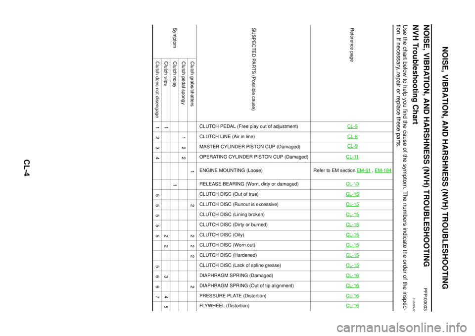
NOISE, VIBRATION, AND HARSHNESS (NVH) TROUBLESHOOTING
NOISE, VIBRATION, AND HARSHNESS (NVH) TROUBLESHOOTING
PFP:00003
NVH Troubleshooting ChartECS004JZ
Use the chart below to help you find the cause of the symptom. The numbers indicate the order of the inspec-
tion. If necessary, repair or replace these parts.
Reference pageCL-5CL-8CL-9CL-11
Refer to EM section.EM-61
,EM-184
CL-13CL-15CL-15CL-15CL-15CL-15CL-15CL-15CL-15CL-16CL-16CL-16CL-16
SUSPECTED PARTS (Possible cause)
CLUTCH PEDAL (Free play out of adjustment)
CLUTCH LINE (Air in line)
MASTER CYLINDER PISTON CUP (Damaged)
OPERATING CYLINDER PISTON CUP (Damaged)
ENGINE MOUNTING (Loose)
RELEASE BEARING (Worn, dirty or damaged)
CLUTCH DISC (Out of true)
CLUTCH DISC (Runout is excessive)
CLUTCH DISC (Lining broken)
CLUTCH DISC (Dirty or burned)
CLUTCH DISC (Oily)
CLUTCH DISC (Worn out)
CLUTCH DISC (Hardened)
CLUTCH DISC (Lack of spline grease)
DIAPHRAGM SPRING (Damaged)
DIAPHRAGM SPRING (Out of tip alignment)
PRESSURE PLATE (Distortion)
FLYWHEEL (Distortion)
SymptomClutch grabs/chatters 1 2 2 2 2 2
Clutch pedal spongy 1 2 2
Clutch noisy 1
Clutch slips 1 2 2 3 4 5
Clutchdoesnotdisengage 1234 55555 5667
Page 2109 of 3066
![NISSAN X-TRAIL 2003 Electronic Repair Manual FUEL SUPPLY PUMP
EM-139
[YD22DDTi]
C
D
E
F
G
H
I
J
K
L
MA
EM
5. Remove RH front wheel.
6. Remove RH splash cover (combined with under cover)
7. Remove fuel hose from fuel supply pump.
8. Remove the ha NISSAN X-TRAIL 2003 Electronic Repair Manual FUEL SUPPLY PUMP
EM-139
[YD22DDTi]
C
D
E
F
G
H
I
J
K
L
MA
EM
5. Remove RH front wheel.
6. Remove RH splash cover (combined with under cover)
7. Remove fuel hose from fuel supply pump.
8. Remove the ha](/img/5/57402/w960_57402-2108.png)
FUEL SUPPLY PUMP
EM-139
[YD22DDTi]
C
D
E
F
G
H
I
J
K
L
MA
EM
5. Remove RH front wheel.
6. Remove RH splash cover (combined with under cover)
7. Remove fuel hose from fuel supply pump.
8. Remove the harness connector from the fuel supply pump.
9. Remove the fuel supply pump rear bracket.
lLoosen the fuel bolts in the reverse order of that show in the
figure and remove them.
10. Remove fuel supply pump center spill tube.
11. Remove front chain case.
lLoosen fixing bolts in the reverse order of that shown in the
figure and remove them.
lRemove No. 6, 10 and 11 bolts with the rubber washer as
space is limited for pulling them out.
CAUTION:
lWhile front chain case is removed, cover openings to
prevent entry of foreign material into engine.
lDo not remove two mass dampers on the back of cover.
12. Set the No. 1 piston to TDC on its compression stroke.
lTurn crankshaft pulley clockwise so that the alignment mark
(punched mark) on each camshaft sprocket is positioned as
showninthefigure.
lNo position indicator is provided on the crankshaft pul-
ley.
lWhen installing, color coded links on the secondary tim-
ing chain can be used as alignment marks. Marking may
not be necessary for removal; however, make alignment
marks as required because the alignment mark on fuel
supply pump sprocket may not be easy to see.
SBIA0214E
JEM121G
SBIA0189E
SEM515G
Page 2211 of 3066
FRONT DRIVE SHAFT
FAX-15
C
E
F
G
H
I
J
K
L
MA
B
FA X
Joint Assembly (Wheel Side)
CAUTION:
Joint assembly cannot be disassembled. Do not attempt to disassemble it.
ASSEMBLY
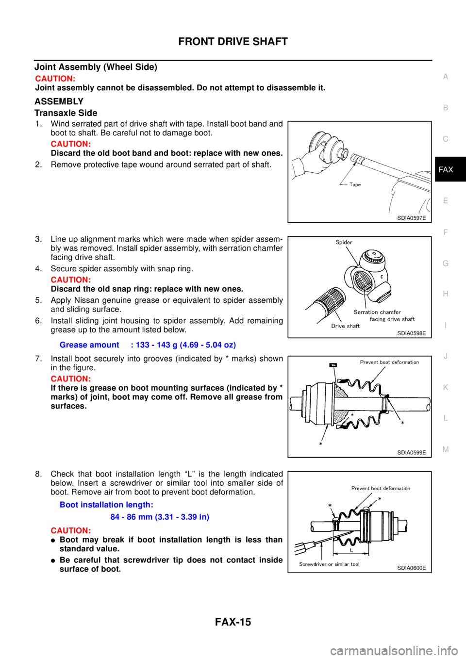
Transaxle Side
1. Wind serrated part of drive shaft with tape. Install boot band and
boot to shaft. Be careful not to damage boot.
CAUTION:
Discard the old boot band and boot: replace with new ones.
2. Remove protective tape wound around serrated part of shaft.
3. Line up alignment marks which were made when spider assem-
bly was removed. Install spider assembly, with serration chamfer
facing drive shaft.
4. Secure spider assembly with snap ring.
CAUTION:
Discard the old snap ring: replace with new ones.
5. Apply Nissan genuine grease or equivalent to spider assembly
and sliding surface.
6. Install sliding joint housing to spider assembly. Add remaining
grease up to the amount listed below.
7. Install boot securely into grooves (indicated by * marks) shown
in the figure.
CAUTION:
If there is grease on boot mounting surfaces (indicated by *
marks) of joint, boot may come off. Remove all grease from
surfaces.
8. Check that boot installation length “L” is the length indicated
below. Insert a screwdriver or similar tool into smaller side of
boot. Remove air from boot to prevent boot deformation.
CAUTION:
lBoot may break if boot installation length is less than
standard value.
lBe careful that screwdriver tip does not contact inside
surface of boot.
SDIA0597E
Grease amount : 133 - 143 g (4.69 - 5.04 oz)
SDIA0598E
SDIA0599E
Boot installation length:
84 - 86 mm (3.31 - 3.39 in)
SDIA0600E
Page 2240 of 3066
FSU-1
FRONT SUSPENSION
E SUSPENSION
CONTENTS
C
D
F
G
H
I
J
K
L
M
SECTION
A
B
FSU
FRONT SUSPENSION
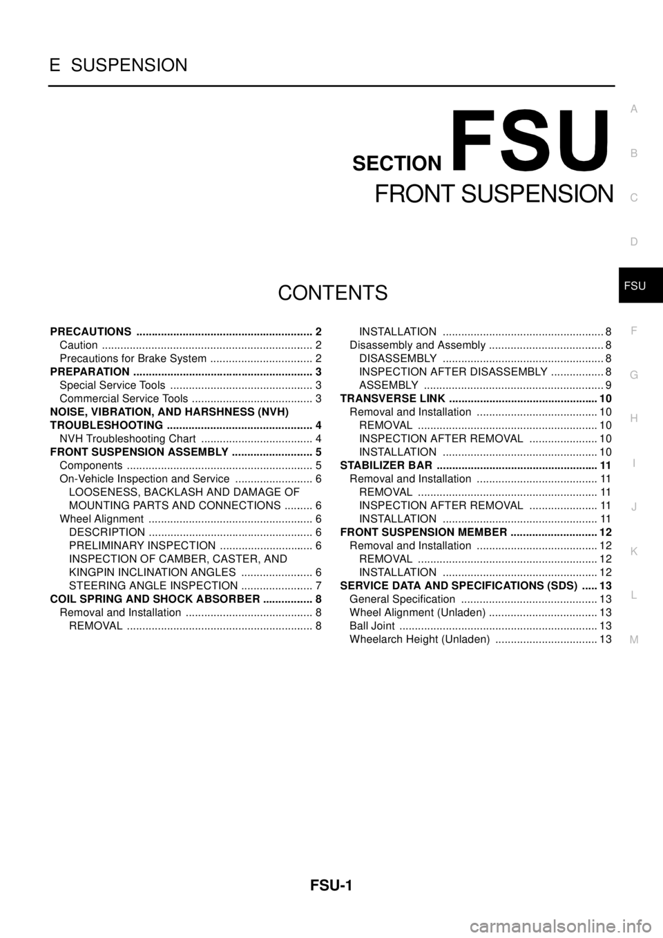
PRECAUTIONS .......................................................... 2
Caution ..................................................................... 2
Precautions for Brake System .................................. 2
PREPARATION ........................................................... 3
Special Service Tools ............................................... 3
Commercial Service Tools ........................................ 3
NOISE, VIBRATION, AND HARSHNESS (NVH)
TROUBLESHOOTING ................................................ 4
NVH Troubleshooting Chart ..................................... 4
FRONT SUSPENSION ASSEMBLY ........................... 5
Components ............................................................. 5
On-Vehicle Inspection and Service .......................... 6
LOOSENESS, BACKLASH AND DAMAGE OF
MOUNTING PARTS AND CONNECTIONS .......... 6
Wheel Alignment ...................................................... 6
DESCRIPTION ...................................................... 6
PRELIMINARY INSPECTION ............................... 6
INSPECTION OF CAMBER, CASTER, AND
KINGPIN INCLINATION ANGLES ........................ 6
STEERING ANGLE INSPECTION ........................ 7
COIL SPRING AND SHOCK ABSORBER ................. 8
Removal and Installation .......................................... 8
REMOVAL ............................................................. 8INSTALLATION ..................................................... 8
Disassembly and Assembly ...................................... 8
DISASSEMBLY ..................................................... 8
INSPECTION AFTER DISASSEMBLY .................. 8
ASSEMBLY ........................................................... 9
TRANSVERSE LINK ................................................. 10
Removal and Installation ........................................ 10
REMOVAL ........................................................... 10
INSPECTION AFTER REMOVAL ....................... 10
INSTALLATION ................................................... 10
STABILIZER BAR ..................................................... 11
Removal and Installation ........................................ 11
REMOVAL ........................................................... 11
INSPECTION AFTER REMOVAL ....................... 11
INSTALLATION ................................................... 11
FRONT SUSPENSION MEMBER ............................. 12
Removal and Installation ........................................ 12
REMOVAL ........................................................... 12
INSTALLATION ................................................... 12
SERVICE DATA AND SPECIFICATIONS (SDS) ...... 13
General Specification ............................................. 13
Wheel Alignment (Unladen) .................................... 13
Ball Joint ................................................................. 13
Wheelarch Height (Unladen) .................................. 13
Page 2241 of 3066
FSU-2
PRECAUTIONS
PRECAUTIONS
PFP:00001
CautionEES0006Z
lWhen installing rubber bushings, final tightening must be carried out under unladen conditions with tires
on flat, level ground. Oil will shorten the life of rubber bushings. Be sure to wipe off any spilled oil.
l“Unladen condition” means that fuel, coolant and lubricant are full and ready for drive. However, spare tire,
jack, and hand tools should be unloaded.
lAfter installing the removed suspension parts, always check wheel alignment and adjust if necessary.
lReplace the caulking nut with a new one. Install a new nut without wiping the oil off before tightening.
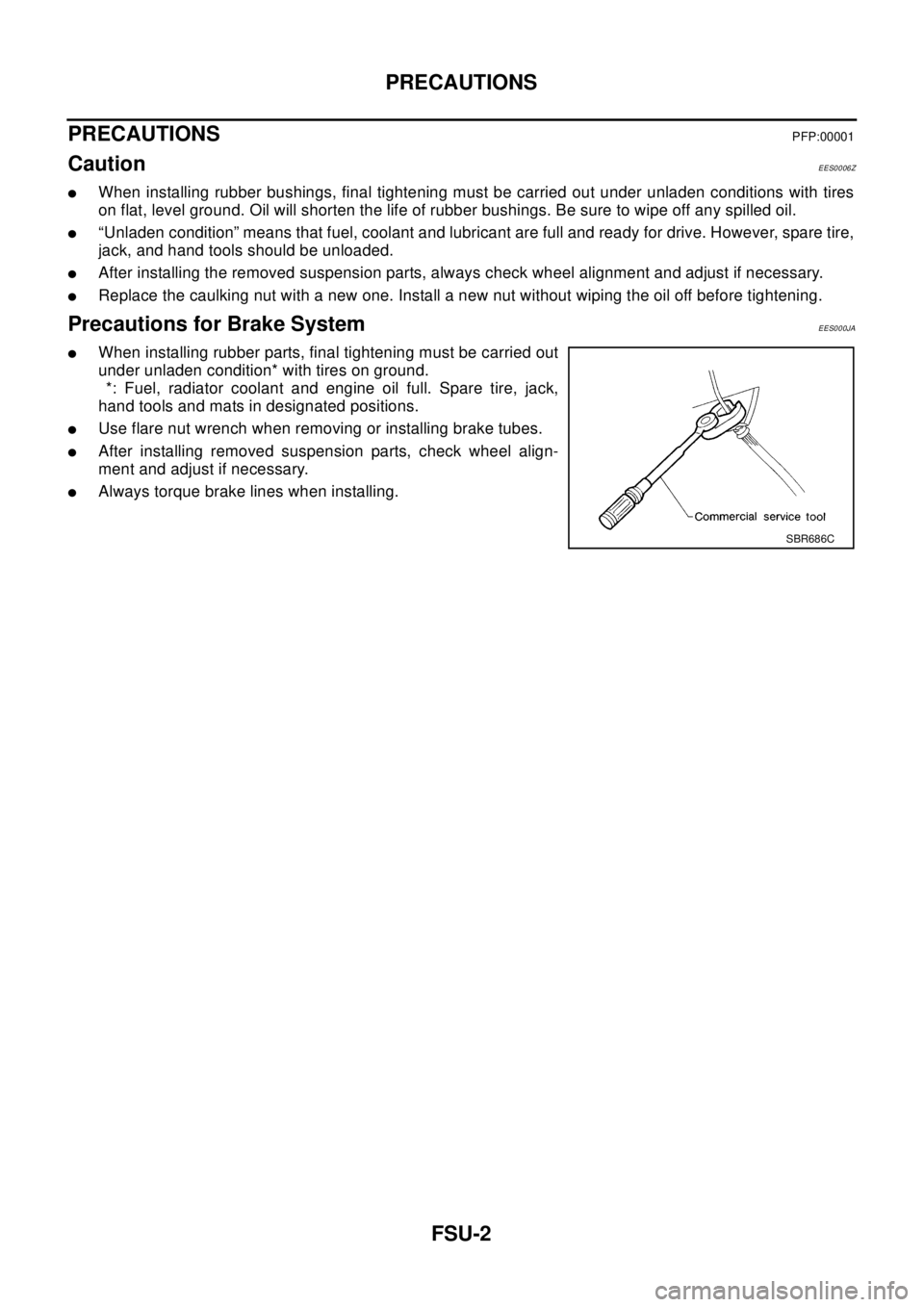
Precautions for Brake SystemEES000JA
lWhen installing rubber parts, final tightening must be carried out
under unladen condition* with tires on ground.
*: Fuel, radiator coolant and engine oil full. Spare tire, jack,
hand tools and mats in designated positions.
lUse flare nut wrench when removing or installing brake tubes.
lAfter installing removed suspension parts, check wheel align-
ment and adjust if necessary.
lAlways torque brake lines when installing.
SBR686C
Page 2242 of 3066
PREPARATION
FSU-3
C
D
F
G
H
I
J
K
L
MA
B
FSU
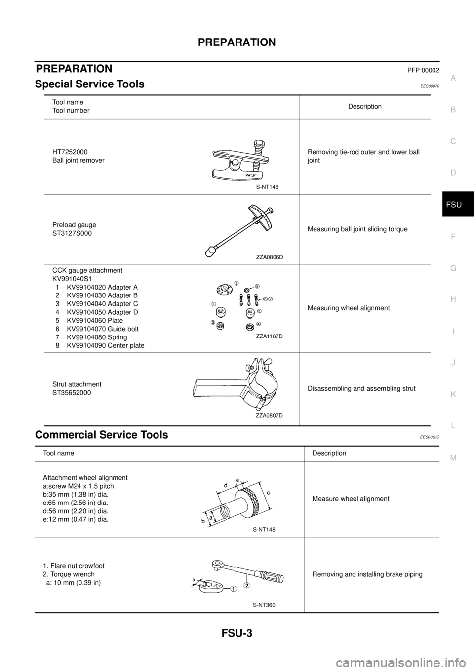
PREPARATIONPFP:00002
Special Service ToolsEES00070
Commercial Service ToolsEES000JC
To o l n a m e
Tool numberDescription
HT7252000
Ball joint removerRemoving tie-rod outer and lower ball
joint
Preload gauge
ST3127S000Measuring ball joint sliding torque
CCK gauge attachment
KV991040S1
1 KV99104020 Adapter A
2 KV99104030 Adapter B
3 KV99104040 Adapter C
4 KV99104050 Adapter D
5 KV99104060 Plate
6 KV99104070 Guide bolt
7 KV99104080 Spring
8 KV99104090 Center plateMeasuring wheel alignment
Strut attachment
ST35652000Disassembling and assembling strut
S-NT146
ZZA0806D
ZZA1167D
ZZA0807D
Tool nameDescription
Attachment wheel alignment
a:screw M24 x 1.5 pitch
b:35 mm (1.38 in) dia.
c:65 mm (2.56 in) dia.
d:56 mm (2.20 in) dia.
e:12 mm (0.47 in) dia.Measure wheel alignment
1. Flare nut crowfoot
2. Torque wrench
a: 10 mm (0.39 in)Removing and installing brake piping
S-NT148
S-NT360
Page 2243 of 3066
FSU-4
NOISE, VIBRATION, AND HARSHNESS (NVH) TROUBLESHOOTING
NOISE, VIBRATION, AND HARSHNESS (NVH) TROUBLESHOOTING
PFP:00003
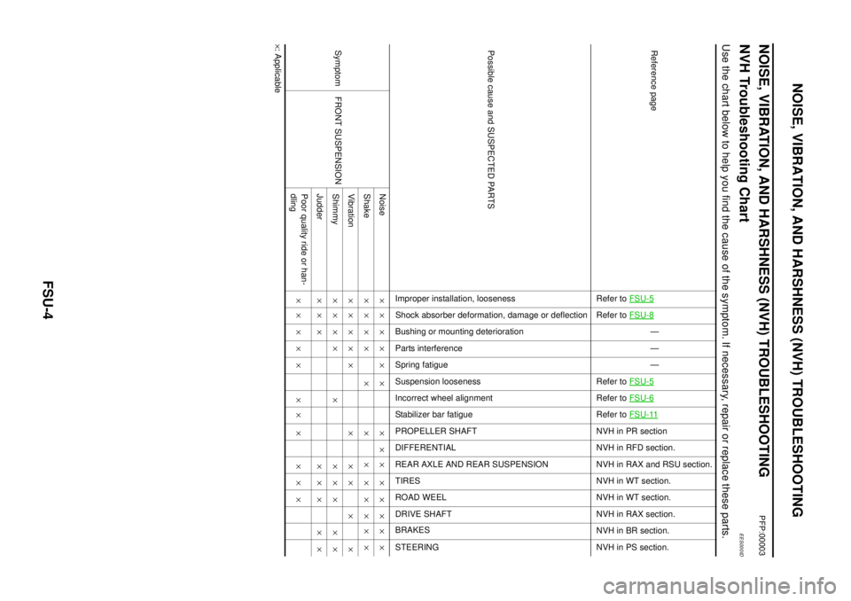
NVH Troubleshooting ChartEES000ID
Use the chart below to help you find the cause of the symptom. If necessary, repair or replace these parts.
´: ApplicableReference page
Refer toFSU-5Refer toFSU-8
—
—
—
Refer toFSU-5
Refer toFSU-6Refer toFSU-11NVH in PR section
NVH in RFD section.
NVHinRAXandRSUsection.
NVH in WT section.
NVH in WT section.
NVH in RAX section.
NVH in BR section.
NVH in PS section.
Possible cause and SUSPECTED PARTS
Improper installation, looseness
Shock absorber deformation, damage or deflection
Bushing or mounting deterioration
Parts interference
Spring fatigue
Suspension looseness
Incorrect wheel alignment
Stabilizer bar fatigue
PROPELLER SHAFT
DIFFERENTIAL
REAR AXLE AND REAR SUSPENSION
TIRES
ROAD WEEL
DRIVE SHAFT
BRAKES
STEERING
Symptom FRONT SUSPENSIONNoise´´´´´ ´ ´´´ ´´´´´
Shake´´´´ ´ ´ ´ ´´´´´
Vibration´´´´´ ´ ´´ ´ ´
Shimmy´´´´ ´ ´´´ ´´
Judder´´´ ´´´ ´´
Poor quality ride or han-
dling´´´´´ ´´ ´ ´´´
Page 2245 of 3066
FSU-6
FRONT SUSPENSION ASSEMBLY
On-Vehicle Inspection and Service
EES00072
LOOSENESS, BACKLASH AND DAMAGE OF MOUNTING PARTS AND CONNECTIONS
Lift vehicle and inspect the following:
lCheck mounting point of each component for looseness, backlash and damage.
lCheck lower ball joint end play.
1. Attach a dial gauge so that the contact rests on the brake caliper.
2. Set front wheels in a straight-ahead position. Do not depress brake pedal.
3. Measure axial endplay by placing an iron pry bar or something similar between transverse link and steer-
ing knuckle.
CAUTION:
Be careful not to damage ball joint boot.
4. If axial endplay is outside the standard, remove transverse link and check lower ball joint.
Wheel AlignmentEES00073
DESCRIPTION
lMeasure wheel alignment under unladen conditions. “Unladen conditions” means that fuel, coolant, and
lubricant are full. However, spare tire, jack, and hand tools should be unloaded.
PRELIMINARY INSPECTION
1. Check the tires for improper air pressure and wear.
2. Check road wheels for runout.
3. Check wheel bearing axial endplay.
4. Check lower ball joint axial endplay.
5. Check strut operation.
6. Check each mounting point of axle and suspension for looseness and deformation.
7. Check each link and arm for cracks, deformation, and other damage.
8. Check the vehicle posture.
INSPECTION OF CAMBER, CASTER, AND KINGPIN INCLINATION ANGLES
lCamber, caster, and kingpin inclination angles cannot be adjusted.
lBefore inspection, mount front wheels onto turning radius gauge. Mount rear wheels onto a stand that has
same height so the vehicle will remain horizontal.
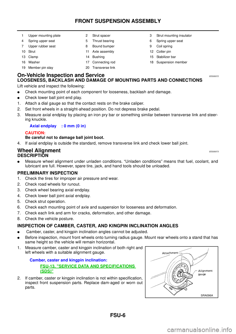
1. Measure camber, caster and kingpin inclination of both right and
left wheels with a suitable alignment gauge.
2. If camber, caster or kingpin inclination is not within specification,
inspect front suspension parts. Replace dam-aged or worn out
parts.
1 Upper mounting plate 2 Strut spacer 3 Strut mounting insulator
4 Spring upper seat 5 Thrust bearing 6 Spring upper seat
7 Upper rubber seat 8 Bound bumper 9 Coil spring
10 Strut 11 Axle assembly 12 Cotter pin
13 Clamp 14 Bushing 15 Stabilizer bar
16 Washer 17 Connecting rod 18 Suspension member
19 Member pin stay 20 Transverse link
Axial endplay : 0 mm (0 in)
Camber, caster and kingpin inclination:
FSU-13, "
SERVICE DATA AND SPECIFICATIONS
(SDS)"
SRA096A