heating NISSAN X-TRAIL 2003 Electronic Repair Manual
[x] Cancel search | Manufacturer: NISSAN, Model Year: 2003, Model line: X-TRAIL, Model: NISSAN X-TRAIL 2003Pages: 3066, PDF Size: 51.47 MB
Page 14 of 3066

AT-8
PRECAUTIONS
lVehicle has TCC shudder and/or no TCC apply. Replace only after all hydraulic and electrical diagnoses
have been made. (Converter clutch material may be glazed.)
lConverter is contaminated with engine coolant containing antifreeze.
lInternal failure of stator roller clutch.
lHeavy clutch debris due to overheating (blue converter).
lSteel particles or clutch lining material found in fluid filter or on magnet when no internal parts in unit are
worn or damaged — indicates that lining material came from converter.
The torque converter should not be replaced if:
lThe fluid has an odor, is discolored, and there is no evidence of metal or clutch facing particles.
lThe threads in one or more of the converter bolt holes are damaged.
lTransaxle failure did not display evidence of damaged or worn internal parts, steel particles or clutch plate
lining material in unit and inside the fluid filter.
lVehicle has been exposed to high mileage (only). The exception may be where the torque converter
clutch dampener plate lining has seen excess wear by vehicles operated in heavy and/or constant traffic,
such as taxi, delivery or police use.
EURO-OBD SELF-DIAGNOSIS — EURO-OBD —
lA/T self-diagnosis is performed by the TCM in combination with the ECM. The results can be read through
the blinking pattern of the O/D OFF indicator lamp or the malfunction indicator lamp (MIL). Refer to the
table onAT-42, "
SELF-DIAGNOSTIC RESULT TEST MODE"for the indicator used to display each self-
diagnostic result.
lThe self-diagnostic results indicated by the MIL are automatically stored in both the ECM and TCM mem-
ories.
Always perform the procedure “HOW TO ERASE DTC” onAT-39, "
HOW TO ERASE DTC"to com-
plete the repair and avoid unnecessary blinking of the MIL.
lThe following self-diagnostic items can be detected using ECM self-diagnostic results mode* only when
the O/D OFF indicator lamp does not indicate any malfunctions.
–PNP switch
–A/T 1st, 2nd, 3rd, or 4th gear function
*: For details of EURO-OBD, refer toAT - 3 7 , "
ON BOARD DIAGNOSTIC SYSTEM DESCRIPTION".
lCertain systems and components, especially those related to EURO-OBD, may use a new style
slide-locking type harness connector.
For description and how to disconnect, refer toPG-70, "
HARNESS CONNECTOR".
Wiring Diagrams and Trouble DiagnosisECS004Q4
When you read wiring diagrams, refer to the following:
lGI-14, "How to Read Wiring Diagrams".
lPG-2, "POWER SUPPLY ROUTING".
When you perform trouble diagnosis, refer to the following:
lGI-11, "HOW TO FOLLOW TEST GROUPS IN TROUBLE DIAGNOSES".
l"", “HOW TO PERFORM EFFICIENT DIAGNOSIS FOR AN ELECTRICAL INCIDENT”
Page 70 of 3066
![NISSAN X-TRAIL 2003 Electronic Repair Manual AT-64
[EURO-OBD]
TROUBLE DIAGNOSIS — BASIC INSPECTION
TROUBLE DIAGNOSIS — BASIC INSPECTION
PFP:00000
A/T Fluid CheckECS0 04 QQ
FLUID LEAKAGE CHECK
1. Clean area suspected of leaking. — for examp NISSAN X-TRAIL 2003 Electronic Repair Manual AT-64
[EURO-OBD]
TROUBLE DIAGNOSIS — BASIC INSPECTION
TROUBLE DIAGNOSIS — BASIC INSPECTION
PFP:00000
A/T Fluid CheckECS0 04 QQ
FLUID LEAKAGE CHECK
1. Clean area suspected of leaking. — for examp](/img/5/57402/w960_57402-69.png)
AT-64
[EURO-OBD]
TROUBLE DIAGNOSIS — BASIC INSPECTION
TROUBLE DIAGNOSIS — BASIC INSPECTION
PFP:00000
A/T Fluid CheckECS0 04 QQ
FLUID LEAKAGE CHECK
1. Clean area suspected of leaking. — for example, mating surface
of converter housing and transmission case.
2. Start engine, apply foot brake, place selector lever in “D” posi-
tion and wait a few minutes.
3. Stop engine.
4. Check for fresh leakage.
FLUID CONDITION CHECK
FLUID LEVEL CHECK
Refer to “Checking A/T Fluid”,AT-13, "A/T FLUID".
SAT767B
SAT288G
Fluid color Suspected problem
Dark or black with burned odor Wear of frictional material
Milky pink Water contamination — Road water
entering through filler tube or breather
Varnished fluid, light to dark brown and
tackyOxidation — Over or under filling, —
Overheating
SAT638A
Page 292 of 3066
![NISSAN X-TRAIL 2003 Electronic Repair Manual AT-286
[EXC.F/EURO-OBD]
TROUBLE DIAGNOSIS — BASIC INSPECTION
TROUBLE DIAGNOSIS — BASIC INSPECTION
PFP:00000
A/T Fluid CheckECS004VR
FLUID LEAKAGE CHECK
1. Clean area suspected of leaking. — for NISSAN X-TRAIL 2003 Electronic Repair Manual AT-286
[EXC.F/EURO-OBD]
TROUBLE DIAGNOSIS — BASIC INSPECTION
TROUBLE DIAGNOSIS — BASIC INSPECTION
PFP:00000
A/T Fluid CheckECS004VR
FLUID LEAKAGE CHECK
1. Clean area suspected of leaking. — for](/img/5/57402/w960_57402-291.png)
AT-286
[EXC.F/EURO-OBD]
TROUBLE DIAGNOSIS — BASIC INSPECTION
TROUBLE DIAGNOSIS — BASIC INSPECTION
PFP:00000
A/T Fluid CheckECS004VR
FLUID LEAKAGE CHECK
1. Clean area suspected of leaking. — for example, mating surface
of converter housing and transmission case.
2. Start engine, apply foot brake, place selector lever in “D” posi-
tion and wait a few minutes.
3. Stop engine.
4. Check for fresh leakage.
FLUID CONDITION CHECK
FLUID LEVEL CHECK
Refer to “Checking A/T Fluid”,AT-13, "A/T FLUID".
SAT767B
SAT288G
Fluid color Suspected problem
Dark or black with burned odor Wear of frictional material
Milky pink Water contamination — Road water
entering through filler tube or breather
Varnished fluid, light to dark brown and
tackyOxidation — Over or under filling, —
Overheating
SAT638A
Page 580 of 3066

ATC-2
DEFROSTER (DEF) SWITCH ............................. 27
MODE SWITCH ................................................... 27
FAN SWITCH ...................................................... 27
OFF SWITCH ...................................................... 27
FRESH (FRE) SWITCH ....................................... 27
RECIRCULATION (REC) SWITCH ..................... 27
Discharge Air Flow ................................................. 28
System Description ................................................. 29
SWITCHES AND THEIR CONTROL FUNCTION... 29
TROUBLE DIAGNOSIS ............................................ 30
How to Perform Trouble Diagnoses for Quick and
Accurate Repair ...................................................... 30
WORK FLOW ...................................................... 30
SYMPTOM TABLE .............................................. 30
Component Parts and Harness Connector Location... 31
ENGINE COMPARTMENT .................................. 31
PASSENGER COMPARTMENT .......................... 32
Circuit Diagram ....................................................... 33
WITH GASOLINE ENGINE ................................. 33
WITH DIESEL ENGINE ....................................... 34
Wiring Diagram ....................................................... 35
WITH DASOLINE ENGINE ................................. 35
WITH DIESEL ENGINE ....................................... 38
Auto Amp. Terminals and Reference Value ............ 41
PIN CONNECTOR TERMINAL LAYOUT ............ 41
AUTO AMP. INSPECTION TABLE ...................... 41
Self-diagnosis Function .......................................... 42
DESCRIPTION .................................................... 42
PROCEDURE ...................................................... 43
AUXILIARY MECHANISM: TEMPERATURE
SETTING TRIMMER ........................................... 49
AUXILIARY MECHANISM: FOOT POSITION
SETTING TRIMMER ........................................... 50
AUXILIARY MECHANISM: INLET PORT MEM-
ORY FUNCTION (FOR LHD MODELS) .............. 51
Operational Check .................................................. 51
CHECKING MEMORY FUNCTION ..................... 51
CHECKING BLOEWER ....................................... 52
CHECKING DISCHARGE AIR ............................ 52
CHECKING RECIRCULATION ............................ 52
CHECKING TEMPERATURE DECREASE ......... 53
CHECKING TEMPERATURE INCREASE .......... 53
CHECKING AUTO MODE ................................... 53
Power Supply and Ground Circuit for Auto Amp. ... 53
INSPECTION FLOW ........................................... 54
COMPONENT DESCRIPTION ............................ 54
DIAGNOSTIC PROCEDURE .............................. 55
LAN System Circuit ................................................ 56
DIAGNOSTIC PROCEDURE .............................. 56
Mode Door Motor Circuit ........................................ 58
INSPECTION FLOW ........................................... 59
SYSTEM DESCRIPTION .................................... 60
COMPONENT DESCRIPTION ............................ 61
DIAGNOSTIC PROCEDURE .............................. 61
Air Mix Door Motor Circuit ...................................... 61
INSPECTION FLOW ........................................... 62
SYSTEM DESCRIPTION .................................... 62
COMPONENT DESCRIPTION ............................ 64DIAGNOSTIC PROCEDURE ...............................64
Intake Door Motor Circuit ........................................64
INSPECTION FLOW ............................................65
SYSTEM DESCRIPTION .....................................65
COMPONENT DESCRIPTION ............................66
DIAGNOSTIC PROCEDURE ...............................67
Blower Motor Circuit ................................................67
INSPECTION FLOW ............................................68
SYSTEM DESCRIPTION .....................................69
COMPONENT DESCRIPTION ............................70
DIAGNOSTIC PROCEDURE ...............................70
COMPONENT INSPECTION ...............................73
Magnet Clutch Circuit ..............................................73
INSPECTION FLOW ............................................74
SYSTEM DESCRIPTION .....................................74
DIAGNOSTIC PROCEDURE ...............................75
COMPONENT INSPECTION ...............................80
Insufficient Cooling ..................................................81
INSPECTION FLOW ............................................82
PERFORMANCE TEST DIAGNOSES ................83
PERFORMANCE CHART ....................................84
TROUBLE DIAGNOSES FOR ABNORMAL
PRESSURE .........................................................86
Insufficient Heating .................................................89
INSPECTION FLOW ............................................90
Noise .......................................................................91
INSPECTION FLOW ............................................91
Self-diagnosis .........................................................92
INSPECTION FLOW ............................................92
Memory Function ....................................................92
INSPECTION FLOW ............................................93
Ambient Sensor Circuit ...........................................93
COMPONENT DESCRIPTION ............................93
AMBIENT TEMPERATURE INPUT PROCESS...93
DIAGNOSTIC PROCEDURE ...............................94
COMPONENT INSPECTION ...............................95
In-vehicle Sensor Circuit .........................................95
COMPONENT DESCRIPTION ............................95
DIAGNOSTIC PROCEDURE ...............................96
COMPONENT INSPECTION ...............................97
Sunload Sensor Circuit ...........................................98
COMPONENT DESCRIPTION ............................98
SUNLOAD INPUT PROCESS .............................98
DIAGNOSTIC PROCEDURE ...............................98
COMPONENT INSPECTION ............................. 100
Intake Sensor Circuit ............................................. 101
COMPONENT DESCRIPTION .......................... 101
DIAGNOSTIC PROCEDURE ............................. 101
CONTROLLER ........................................................ 104
Removal and Installation ....................................... 104
Disassembly and Assembly .................................. 104
AMBIENT SENSOR ................................................ 105
Removal and Installation ....................................... 105
IN-VEHICLE SENSOR ............................................ 106
Removal and Installation ....................................... 106
SUNLOAD SENSOR ............................................... 107
Removal and Installation ....................................... 107
Page 608 of 3066

ATC-30
TROUBLE DIAGNOSIS
TROUBLE DIAGNOSIS
PFP:00004
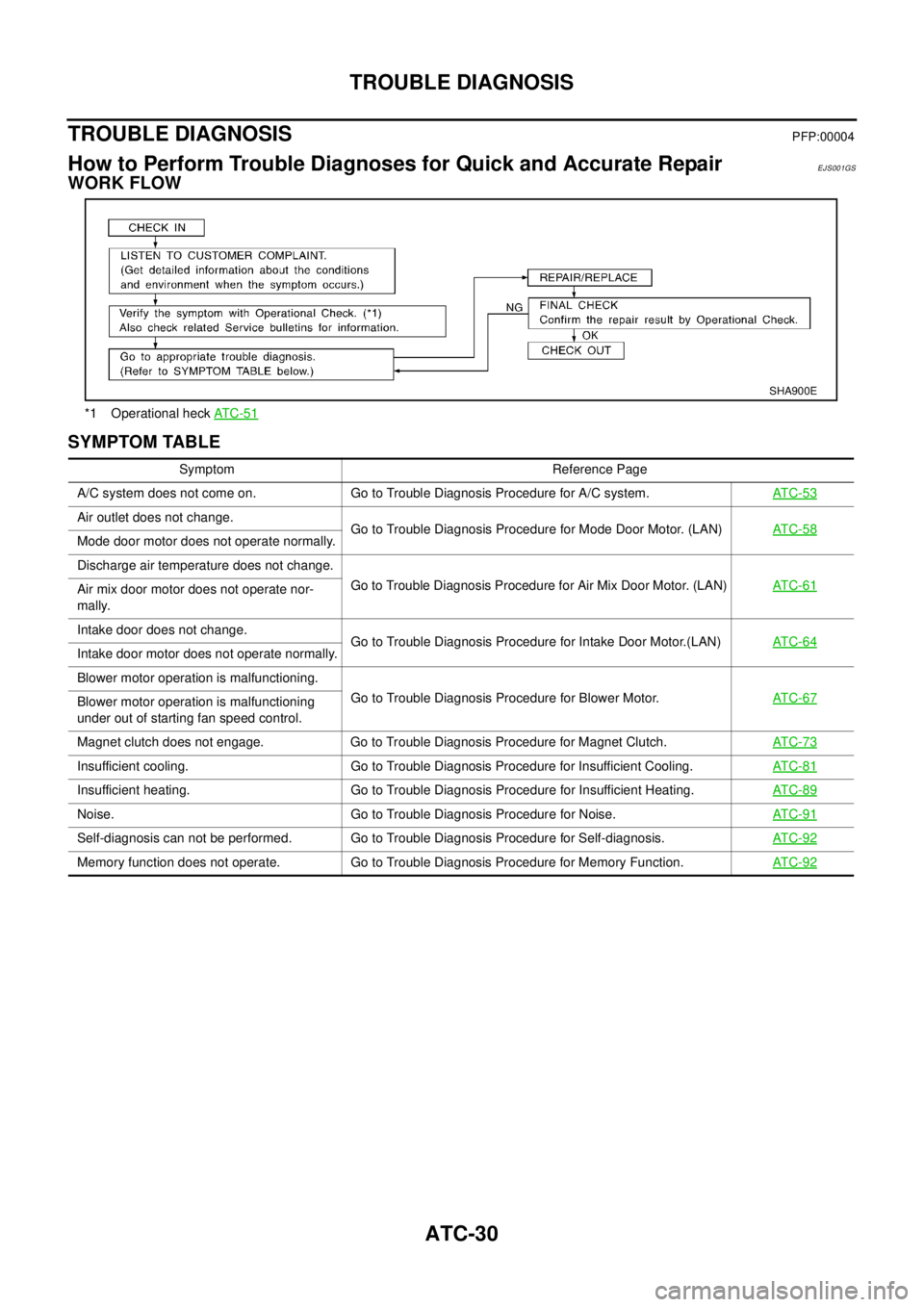
How to Perform Trouble Diagnoses for Quick and Accurate RepairEJS001GS
WORK FLOW
SYMPTOM TABLE
*1 Operational heckAT C -5 1
SHA900E
Symptom Reference Page
A/C system does not come on. Go to Trouble Diagnosis Procedure for A/C system.AT C - 5 3
Air outlet does not change.
Go to Trouble Diagnosis Procedure for Mode Door Motor. (LAN)AT C - 5 8
Mode door motor does not operate normally.
Discharge air temperature does not change.
Go to Trouble Diagnosis Procedure for Air Mix Door Motor. (LAN)AT C - 6 1
Air mix door motor does not operate nor-
mally.
Intake door does not change.
Go to Trouble Diagnosis Procedure for Intake Door Motor.(LAN)AT C - 6 4
Intake door motor does not operate normally.
Blower motor operation is malfunctioning.
Go to Trouble Diagnosis Procedure for Blower Motor.AT C - 6 7
Blower motor operation is malfunctioning
under out of starting fan speed control.
Magnet clutch does not engage. Go to Trouble Diagnosis Procedure for Magnet Clutch.AT C - 7 3
Insufficient cooling. Go to Trouble Diagnosis Procedure for Insufficient Cooling.AT C - 8 1
Insufficient heating. Go to Trouble Diagnosis Procedure for Insufficient Heating.AT C - 8 9
Noise. Go to Trouble Diagnosis Procedure for Noise.AT C - 9 1
Self-diagnosis can not be performed. Go to Trouble Diagnosis Procedure for Self-diagnosis.AT C - 9 2
Memory function does not operate. Go to Trouble Diagnosis Procedure for Memory Function.AT C - 9 2
Page 631 of 3066

TROUBLE DIAGNOSIS
ATC-53
C
D
E
F
G
H
I
K
L
MA
B
AT C
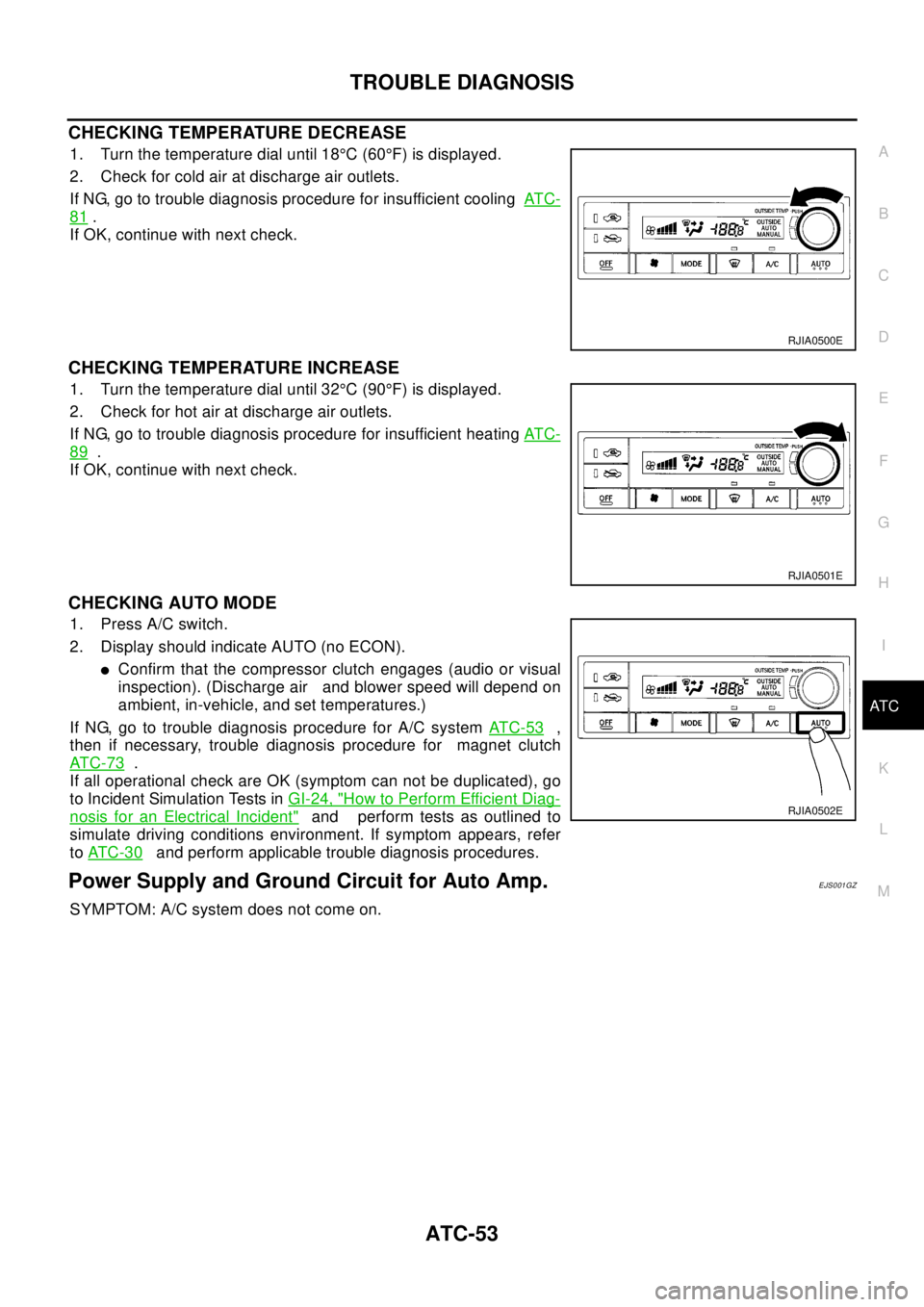
CHECKING TEMPERATURE DECREASE
1. Turn the temperature dial until 18°C(60°F) is displayed.
2. Check for cold air at discharge air outlets.
If NG, go to trouble diagnosis procedure for insufficient coolingAT C -
81.
If OK, continue with next check.
CHECKING TEMPERATURE INCREASE
1. Turn the temperature dial until 32°C(90°F) is displayed.
2. Check for hot air at discharge air outlets.
If NG, go to trouble diagnosis procedure for insufficient heatingAT C -
89.
If OK, continue with next check.
CHECKING AUTO MODE
1. Press A/C switch.
2. Display should indicate AUTO (no ECON).
lConfirm that the compressor clutch engages (audio or visual
inspection). (Discharge air and blower speed will depend on
ambient, in-vehicle, and set temperatures.)
If NG, go to trouble diagnosis procedure for A/C systemAT C - 5 3
,
then if necessary, trouble diagnosis procedure for magnet clutch
AT C - 7 3
.
If all operational check are OK (symptom can not be duplicated), go
to Incident Simulation Tests inGI-24, "
How to Perform Efficient Diag-
nosis for an Electrical Incident"and perform tests as outlined to
simulate driving conditions environment. If symptom appears, refer
toAT C - 3 0
and perform applicable trouble diagnosis procedures.
Power Supply and Ground Circuit for Auto Amp.EJS001GZ
SYMPTOM: A/C system does not come on.
RJIA0500E
RJIA0501E
RJIA0502E
Page 667 of 3066

TROUBLE DIAGNOSIS
ATC-89
C
D
E
F
G
H
I
K
L
MA
B
AT C
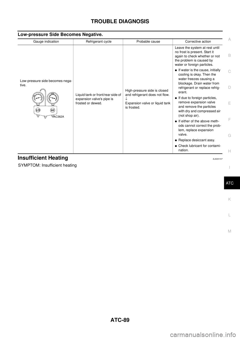
Low-pressure Side Becomes Negative.
Insufficient HeatingEJS001H7
SYMPTOM: Insufficient heating
Gauge indication Refrigerant cycle Probable cause Corrective action
Low-pressure side becomes nega-
tive.
Liquid tank or front/rear side of
expansion valve's pipe is
frosted or dewed.High-pressure side is closed
and refrigerant does not flow.
¯
Expansion valve or liquid tank
is frosted.Leave the system at rest until
no frost is present. Start it
again to check whether or not
the problem is caused by
water or foreign particles.
lIf water is the cause, initially
cooling is okay. Then the
water freezes causing a
blockage. Drain water from
refrigerant or replace refrig-
erant.
lIf due to foreign particles,
remove expansion valve
and remove the particles
with dry and compressed air
(not shop air).
lIf either of the above meth-
ods cannot correct the prob-
lem, replace expansion
valve.
lReplace desiccant assy.
lCheck lubricant for contami-
nation.
AC362A
Page 899 of 3066
![NISSAN X-TRAIL 2003 Electronic Repair Manual TROUBLE DIAGNOSIS
BRC-31
[4WD/ABS]
C
D
E
G
H
I
J
K
L
MA
B
BRC
Continuity exists, resistance value
Insulation inspection
lCheck resistance value between each pair of ABS solenoid E70 and E71 terminals NISSAN X-TRAIL 2003 Electronic Repair Manual TROUBLE DIAGNOSIS
BRC-31
[4WD/ABS]
C
D
E
G
H
I
J
K
L
MA
B
BRC
Continuity exists, resistance value
Insulation inspection
lCheck resistance value between each pair of ABS solenoid E70 and E71 terminals](/img/5/57402/w960_57402-898.png)
TROUBLE DIAGNOSIS
BRC-31
[4WD/ABS]
C
D
E
G
H
I
J
K
L
MA
B
BRC
Continuity exists, resistance value
Insulation inspection
lCheck resistance value between each pair of ABS solenoid E70 and E71 terminals (No.1 (L), 2 ((R/B) 3
(L/W), 12 (Y/G), 25 (L/Y), 26 (B/Y), 27 (L/R), 28 (W/G).
ABS motor operation inspection
1. Connect 2-pin connector on ABS actuator E69 terminals No. 9
(R/B) and No. 10 (Y).
2. Apply voltage of Approx. 12V voltage between terminals E70
No. 5 (G/R) and terminals E71 No. 7 (W/G) on ABS relay unit.
Measure motor voltage (terminal E70 No. 4 (R/Y) - Body
ground) using an oscilloscope and check motor counter electro-
motive force duration when operation stops.
CAUTION:
lBefore measuring time, check each part of ABS relay unit
and confirm motor relay is normal.
lTo prevent overheating, ABS motor should be driven no
longer than 4 seconds.
lMotor counter electromotive force duration is based on the
time at 20°C, in ambient temperatures, with 12V battery volt-
age. If battery voltage is low, time will be slightly shorter.
SFIA0353E
Standard : 5.8 - 21.2 (W)
Motor counter electromotive force duration:
0.1 second or longer
SFIA0354E
Page 980 of 3066
![NISSAN X-TRAIL 2003 Electronic Repair Manual BRC-112
[ESP/TCS/ABS]
TROUBLE DIAGNOSIS
Actuator operation check
1. Connect 19 and 21 terminals of actuator to 40 and 41 terminals
of relay box.
2. Measure the motor voltage (No.4 terminal to body ear NISSAN X-TRAIL 2003 Electronic Repair Manual BRC-112
[ESP/TCS/ABS]
TROUBLE DIAGNOSIS
Actuator operation check
1. Connect 19 and 21 terminals of actuator to 40 and 41 terminals
of relay box.
2. Measure the motor voltage (No.4 terminal to body ear](/img/5/57402/w960_57402-979.png)
BRC-112
[ESP/TCS/ABS]
TROUBLE DIAGNOSIS
Actuator operation check
1. Connect 19 and 21 terminals of actuator to 40 and 41 terminals
of relay box.
2. Measure the motor voltage (No.4 terminal to body earth ) with
oscilloscope. Then check the motor reverse voltage occasioned
time.
The motor reverse voltage occasioned time is more than 0.1
sec.
CAUTION:
lPerform checking of motor relay unit .Then confirm that
relay functions.
lDriving actuator motor is with in 4 sec to prevent heating
up.
lStandard condition of the motor reverse voltage occa-
sioned time is: Battery voltage is 12V. temperature 20°.
when the battery voltage or temperature is lower than the
standard, the motor reverse voltage occasioned time
becomesslightlyshorter.
Symptom 1: ABS Works Frequently.EFS001AS
Inspection procedure
1.INSPECTION START
Check the wheel speed sensor system.
lSensor mounting inspection
lSensor pick-up inspection for iron chips
lSensor rotor inspection (e.g. number of teeth, damaged teeth)
lSensor connector engagement inspection
Is inspection result OK?
YES >> GO TO 2.
NO >> Refer to wheel speed sensor and rotor lines.
2.LOOSENESS INSPECTION
Check the front axle for looseness.
Is inspection result OK?
YES >>BRC-112, "Symptom 2: Unexpected Pedal Action"
NO >> Axle inspection and repair
Symptom 2: Unexpected Pedal ActionEFS001AT
Inspection procedure
1.BRAKE PEDAL STROKE INSPECTION
Check the brake pedal stroke.
Is stroke excessively long?
YES >> Check the bleeding and brake system.
NO >> GO TO 2.
SFIA0400E
Page 1011 of 3066

CO-1
ENGINE COOLING SYSTEM
B ENGINE
CONTENTS
C
D
E
F
G
H
I
J
K
L
M
SECTION
A
CO
ENGINE COOLING SYSTEM
QR20DE
PRECAUTIONS .......................................................... 3
Precautions For Liquid Gasket ................................. 3
REMOVAL OF LIQUID GASKET .......................... 3
LIQUID GASKET APPLICATION PROCEDURE..... 3
PREPARATION ........................................................... 4
Special Service Tools ............................................... 4
OVERHEATING CAUSE ANALYSIS .......................... 5
Troubleshooting Chart .............................................. 5
COOLING SYSTEM .................................................... 7
Cooling Circuit .......................................................... 7
ENGINE COOLANT .................................................... 9
Inspection ................................................................. 9
LEVEL CHECK ..................................................... 9
LEAK CHECK ....................................................... 9
Changing Engine Coolant ........................................ 9
DRAINING ENGINE COOLANT ........................... 9
REFILLING ENGINE COOLANT ........................ 10
FLUSHING COOLING SYSTEM ......................... 10
RADIATOR ................................................................ 12
Removal and Installation ........................................ 12
REMOVAL ........................................................... 12
INSTALLATION ................................................... 12
Disassembly and Assembly Radiator Fan ............. 13
DISASSEMBLY ................................................... 13
ASSEMBLY ......................................................... 13
INSPECTION ......................................................... 13
CHECKING RADIATOR CAP .............................. 13
CHECKING RADIATOR ...................................... 14
RADIATOR (ALUMINUM TYPE) .............................. 15
Disassembly and Assembly ................................... 15
PREPARATION ................................................... 15
DISASSEMBLY ................................................... 15
ASSEMBLY ......................................................... 16
INSPECTION ...................................................... 18WATER PUMP .......................................................... 19
Removal and Installation ........................................ 19
REMOVAL ........................................................... 19
INSPECTION AFTER REMOVAL ....................... 20
INSTALLATION ................................................... 20
INSPECTION AFTER INSTALLATION ................ 20
THERMOSTAT AND WATER CONTROL VALVE .... 21
Removal and Installation ........................................ 21
REMOVAL ........................................................... 21
INSPECTION AFTER REMOVAL ....................... 22
INSTALLATION ................................................... 22
SERVICE DATA AND SPECIFICATIONS (SDS) ...... 23
Capacity .................................................................. 23
Thermostat ............................................................. 23
Water Control Valve ................................................ 23
Radiator .................................................................. 23
Tightening Torque ................................................... 23
YD22DDTi
PRECAUTIONS ........................................................ 24
Precautions For Liquid Gasket ............................... 24
REMOVAL AND LIQUID GASKET ...................... 24
LIQUID GASKET APPLICATION PROCEDURE... 24
PREPARATION ......................................................... 25
Special Service Tools ............................................. 25
OVERHEATING CAUSE ANALYSIS ........................ 26
Troubleshooting Chart ............................................ 26
COOLING SYSTEM .................................................. 28
Cooling Circuit ........................................................ 28
ENGINE COOLANT .................................................. 30
Inspection ............................................................... 30
LEVEL CHECK .................................................... 30
LEAK CHECK ...................................................... 30
Changing Engine Coolant ....................................... 30
DRAINING ENGINE COOLANT .......................... 30
REFILLING ENGINE COOLANT ......................... 31
FLUSHING COOLING SYSTEM ......................... 32
RADIATOR ................................................................ 33
Removal and Installation ........................................ 33