NISSAN X-TRAIL 2003 Electronic Repair Manual
Manufacturer: NISSAN, Model Year: 2003, Model line: X-TRAIL, Model: NISSAN X-TRAIL 2003Pages: 3066, PDF Size: 51.47 MB
Page 2671 of 3066
PARKING BRAKE SHOE
PB-5
C
D
E
G
H
I
J
K
L
MA
B
PB
PARKING BRAKE SHOEPFP:44060
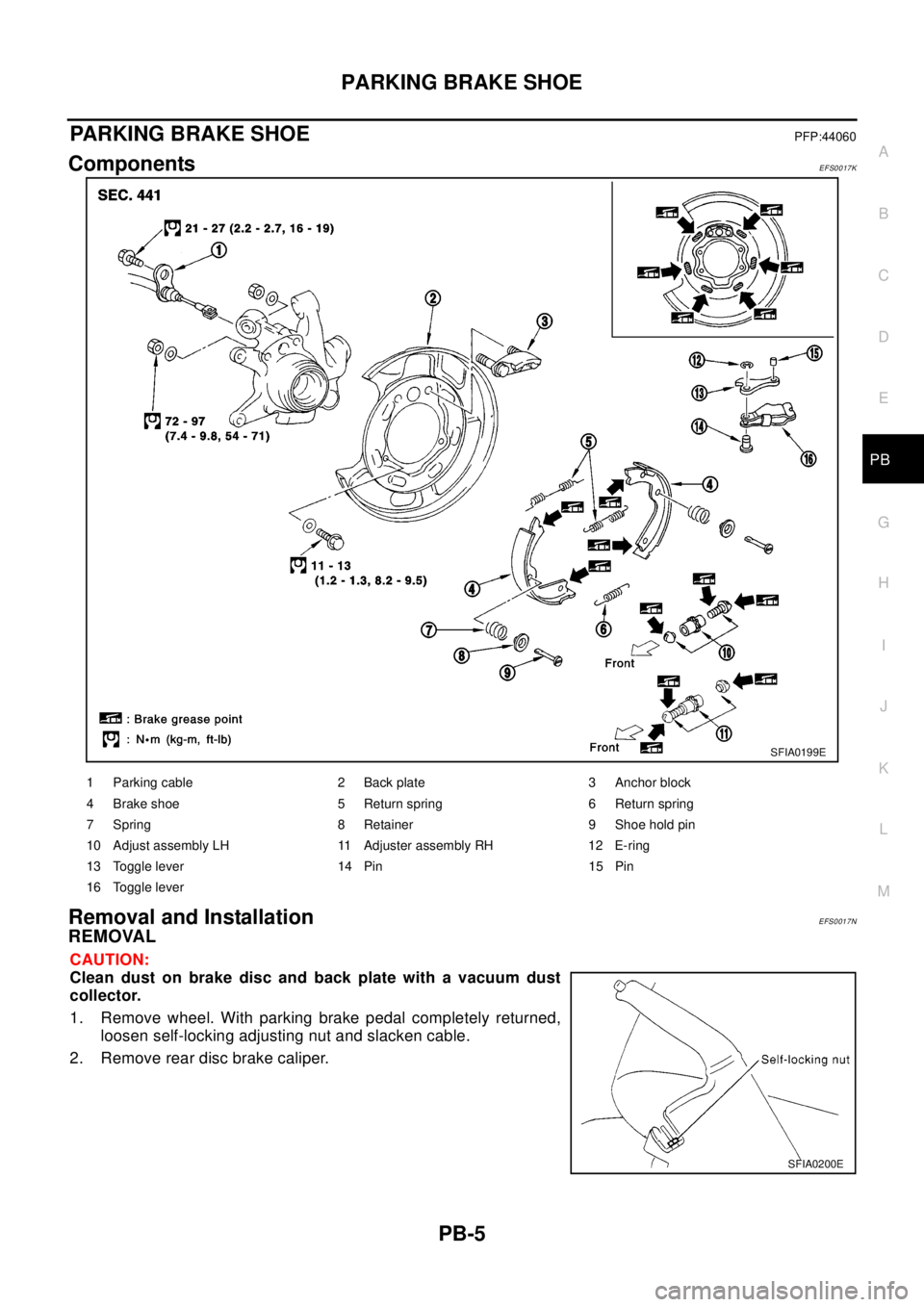
ComponentsEFS0017K
Removal and InstallationEFS0017N
REMOVAL
CAUTION:
Clean dust on brake disc and back plate with a vacuum dust
collector.
1. Remove wheel. With parking brake pedal completely returned,
loosen self-locking adjusting nut and slacken cable.
2. Remove rear disc brake caliper.
SFIA0199E
1 Parking cable 2 Back plate 3 Anchor block
4 Brake shoe 5 Return spring 6 Return spring
7 Spring 8 Retainer 9 Shoe hold pin
10 Adjust assembly LH 11 Adjuster assembly RH 12 E-ring
13 Toggle lever 14 Pin 15 Pin
16 Toggle lever
SFIA0200E
Page 2672 of 3066
PB-6
PARKING BRAKE SHOE
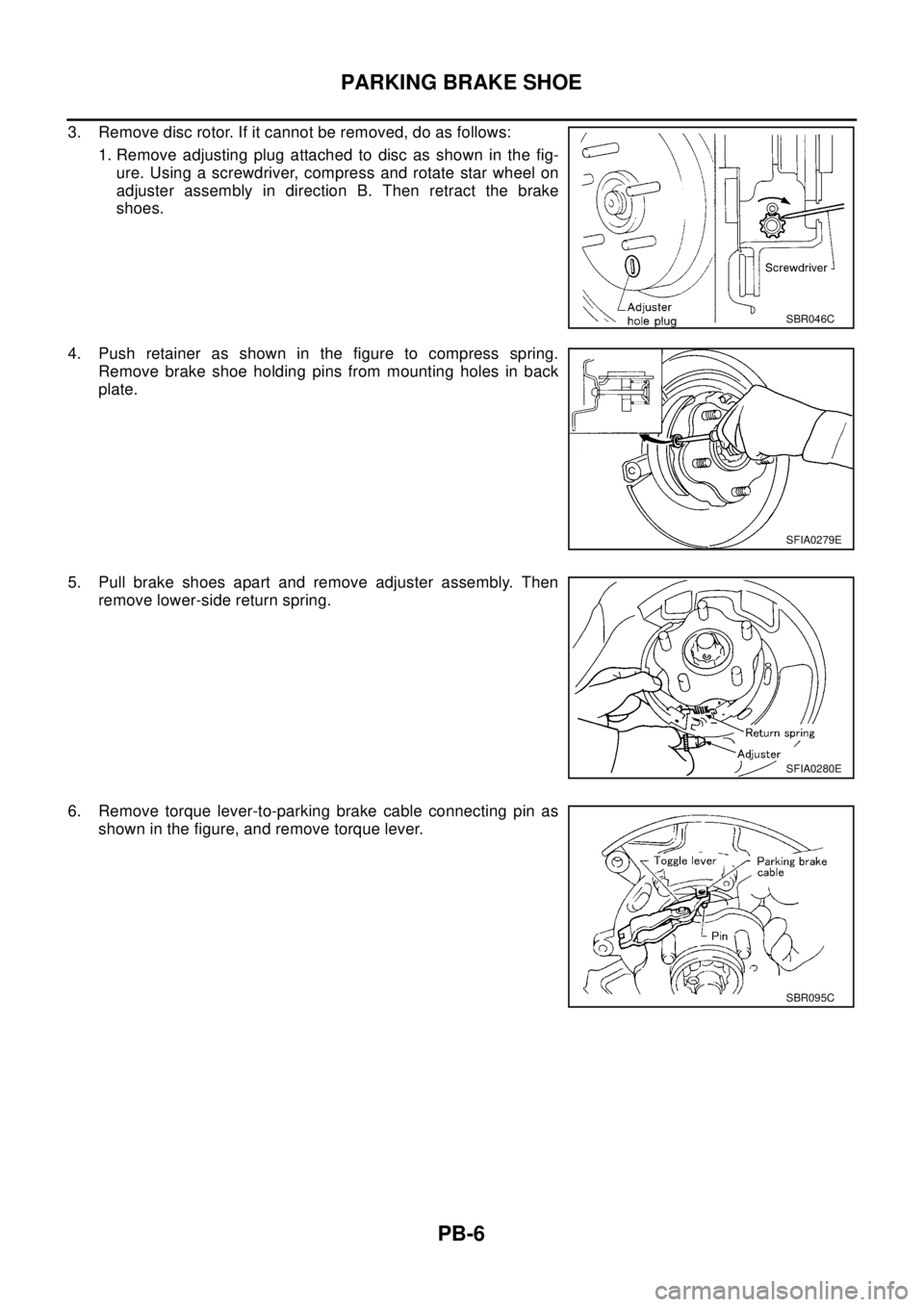
3. Remove disc rotor. If it cannot be removed, do as follows:
1.Removeadjustingplugattachedtodiscasshowninthefig-
ure. Using a screwdriver, compress and rotate star wheel on
adjuster assembly in direction B. Then retract the brake
shoes.
4. Push retainer as shown in the figure to compress spring.
Remove brake shoe holding pins from mounting holes in back
plate.
5. Pull brake shoes apart and remove adjuster assembly. Then
remove lower-side return spring.
6. Remove torque lever-to-parking brake cable connecting pin as
shown in the figure, and remove torque lever.
SBR046C
SFIA0279E
SFIA0280E
SBR095C
Page 2673 of 3066
PARKING BRAKE SHOE
PB-7
C
D
E
G
H
I
J
K
L
MA
B
PB
INSPECTION
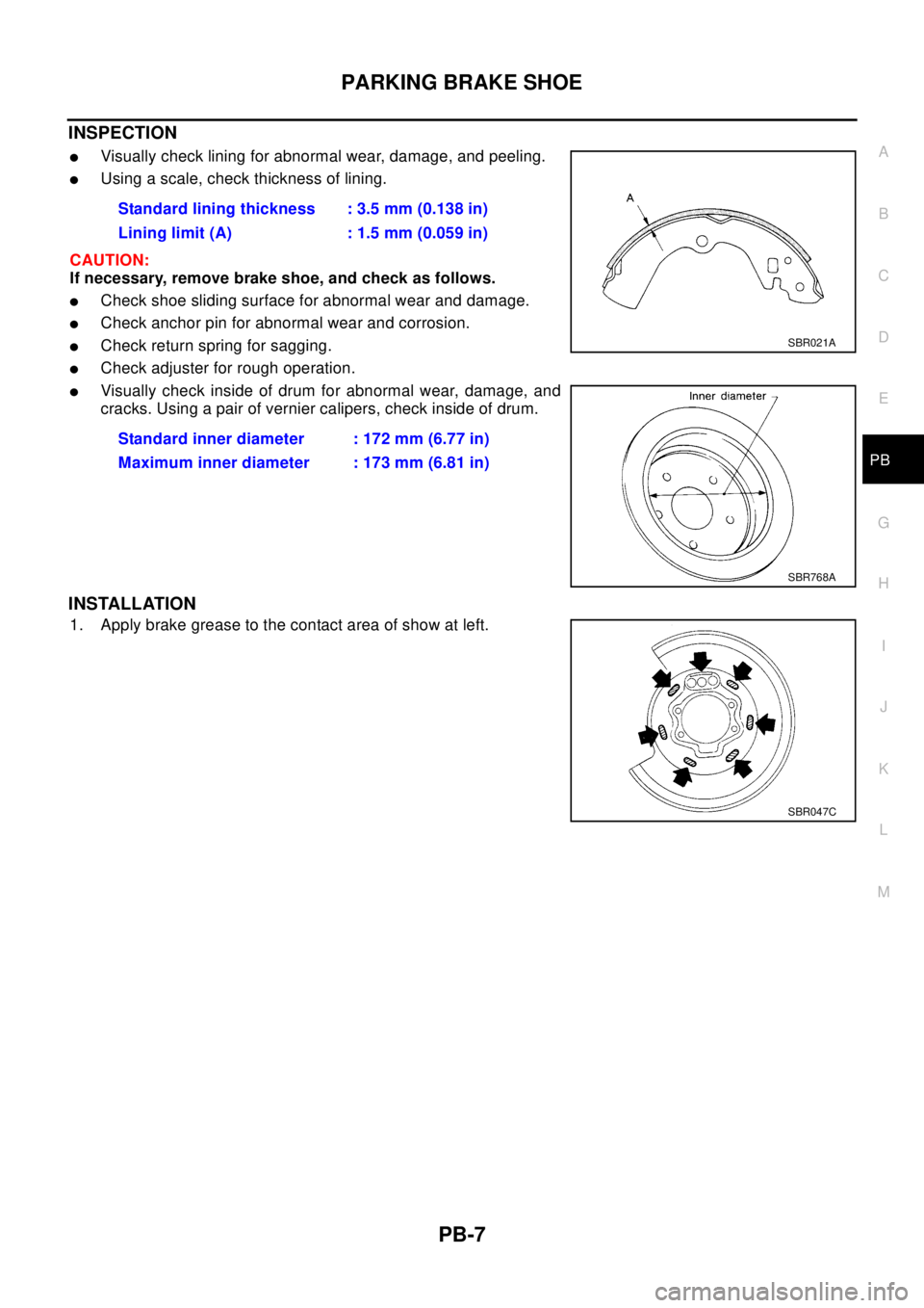
lVisually check lining for abnormal wear, damage, and peeling.
lUsing a scale, check thickness of lining.
CAUTION:
If necessary, remove brake shoe, and check as follows.
lCheck shoe sliding surface for abnormal wear and damage.
lCheck anchor pin for abnormal wear and corrosion.
lCheck return spring for sagging.
lCheck adjuster for rough operation.
lVisually check inside of drum for abnormal wear, damage, and
cracks. Using a pair of vernier calipers, check inside of drum.
INSTALLATION
1. Apply brake grease to the contact area of show at left.Standard lining thickness : 3.5 mm (0.138 in)
Lining limit (A) : 1.5 mm (0.059 in)
Standard inner diameter : 172 mm (6.77 in)
Maximum inner diameter : 173 mm (6.81 in)
SBR021A
SBR768A
SBR047C
Page 2674 of 3066
PB-8
PARKING BRAKE SHOE
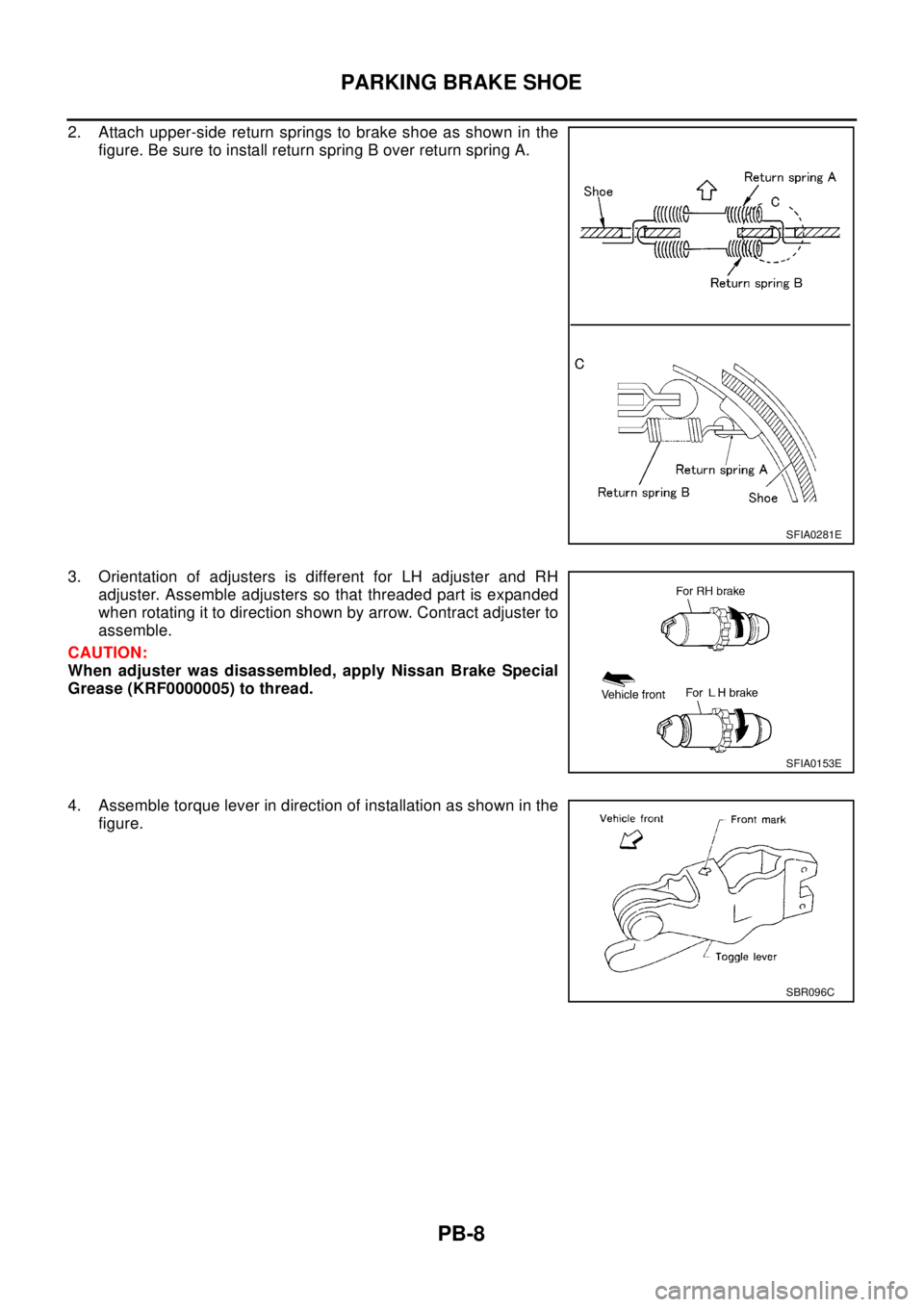
2. Attach upper-side return springs to brake shoe as shown in the
figure. Be sure to install return spring B over return spring A.
3. Orientation of adjusters is different for LH adjuster and RH
adjuster. Assemble adjusters so that threaded part is expanded
when rotating it to direction shown by arrow. Contract adjuster to
assemble.
CAUTION:
When adjuster was disassembled, apply Nissan Brake Special
Grease (KRF0000005) to thread.
4. Assemble torque lever in direction of installation as shown in the
figure.
SFIA0281E
SFIA0153E
SBR096C
Page 2675 of 3066
PARKING BRAKE SHOE
PB-9
C
D
E
G
H
I
J
K
L
MA
B
PB
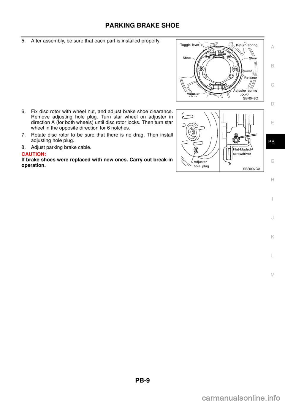
5. After assembly, be sure that each part is installed properly.
6. Fix disc rotor with wheel nut, and adjust brake shoe clearance.
Remove adjusting hole plug. Turn star wheel on adjuster in
direction A (for both wheels) until disc rotor locks. Then turn star
wheel in the opposite direction for 6 notches.
7. Rotate disc rotor to be sure that there is no drag. Then install
adjusting hole plug.
8. Adjust parking brake cable.
CAUTION:
If brake shoes were replaced with new ones. Carry out break-in
operation.
SBR048C
SBR097CA
Page 2676 of 3066

PB-10
SERVICE DATA AND SPECIFICATIONS (SDS)
SERVICE DATA AND SPECIFICATIONS (SDS)
PFP:00030
Parking BrakeEFS000D2
Ty p eDS17H
Brake liningStandard thickness (new) 3.5 mm (0.138 in)
Repair limit thickness 1.5 mm (0.059 in)
Drum (disc)Standard inner diameter (new) 172 mm (6.7 7in)
Wear limit of inner diameter 173 mm (6.81 in)
Lever stroke [operating force 196 N (20 kg,44 lb)] 6 to 7 notches
To t a l s t r o k e18 notches
Brake warning lamp strokeWithin 1 notch
Page 2677 of 3066

PG-1
POWER SUPPLY, GROUND & CIRCUIT ELEMENTS
K ELECTRICAL
CONTENTS
C
D
E
F
G
H
I
J
L
M
SECTION
A
B
PG
POWER SUPPLY, GROUND & CIRCUIT ELEMENTS
POWER SUPPLY ROUTING ...................................... 2
Schematic ................................................................ 2
Wiring Diagram — POWER — ................................. 3
BATTERY POWER SUPPLY — IGNITION SW.
IN ANY POSITION ................................................ 3
ACCESSORY POWER SUPPLY — IGNITION
SW. IN “ACC” OR “ON” ......................................... 7
IGNITION POWER SUPPLY — IGNITION SW.
IN “ON” AND/OR “START” .................................... 8
Fuse ....................................................................... 12
Fusible Link ............................................................ 12
Circuit Breaker ....................................................... 12
GROUND .................................................................. 13
Ground Distribution ................................................ 13
MAIN HARNESS/LHD MODELS ........................ 14
MAIN HARNESS/RHD MODELS ........................ 16
ENGINE ROOM HARNESS/LHD MODELS ....... 18
ENGINE ROOM HARNESS/RHD MODELS ....... 19
ENGINE ROOM HARNESS ................................ 20
ENGINE CONTROL HARNESS/GASOLINE
ENGINE MODELS .............................................. 21
ENGINE CONTROL HARNESS/DIESEL
ENGINE MODELS .............................................. 22
BODY HARNESS/LHD MODELS ....................... 23
BODY HARNESS/RHD MODELS ....................... 24
BODY NO.2 HARNESS/LHD MODELS .............. 25
BODY NO.2 HARNESS/RHD MODELS ............. 26
BODY NO.2 HARNESS ...................................... 27
BACK DOOR SUB HARNESS/REAR WINDOW
DEFOGGER HARNESS ..................................... 28
HARNESS ................................................................. 29
Harness Layout ...................................................... 29
HOW TO READ HARNESS LAYOUTS ............... 29
OUTLINE/LHD MODELS .................................... 30
OUTLINE/RHD MODELS .................................... 31
MAIN HARNESS/LHD MODELS ........................ 32
MAIN HARNESS/RHD MODELS ........................ 34ENGINE ROOM HARNESS/LHD MODELS ........ 36
ENGINE ROOM HARNESS/RHD MODELS ....... 41
ENGINE CONTROL HARNESS .......................... 46
BODY HARNESS/LHD MODELS ....................... 49
BODY HARNESS/RHD MODELS ....................... 50
BODY NO.2 HARNESS/LHD MODELS .............. 51
BODY NO.2 HARNESS/RHD MODELS .............. 52
ROOM LAMP HARNESS .................................... 53
FRONT DOOR HARNESS/LHD MODELS .......... 54
FRONT DOOR HARNESS/RHD MODELS ......... 56
REAR DOOR HARNESS .................................... 58
BACK DOOR HARNESS .................................... 60
Wiring Diagram Codes (Cell Codes) ...................... 61
ELECTRICAL UNITS LOCATION ............................ 64
Electrical Units Location ......................................... 64
ENGINE COMPARTMENT .................................. 65
PASSENGER COMPARTMENT/LHD MODELS... 66
PASSENGER COMPARTMENT/RHD MODELS... 68
HARNESS CONNECTOR ......................................... 70
Description .............................................................. 70
HARNESS CONNECTOR (TAB-LOCKING
TYPE) .................................................................. 70
HARNESS CONNECTOR (SLIDE-LOCKING
TYPE) .................................................................. 71
JOINT CONNECTOR (J/C) ....................................... 72
Terminal Arrangement ............................................ 72
ELECTRICAL UNITS ................................................ 73
Terminal Arrangement ............................................ 73
STANDARDIZED RELAY .......................................... 74
Description .............................................................. 74
NORMAL OPEN, NORMAL CLOSED AND
MIXED TYPE RELAYS ........................................ 74
TYPE OF STANDARDIZED RELAYS ................. 74
FUSE BLOCK-JUNCTION BOX(J/B) ....................... 76
Terminal Arrangement ............................................ 76
FUSE AND FUSIBLE LINK BOX .............................. 77
Terminal Arrangement ............................................ 77
Page 2678 of 3066
PG-2
POWER SUPPLY ROUTING
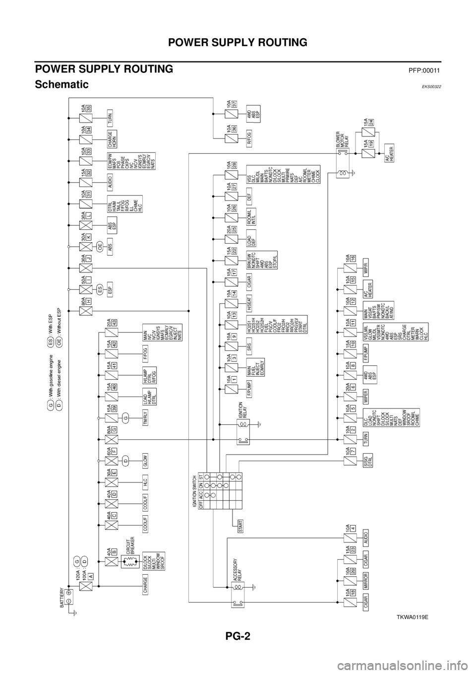
POWER SUPPLY ROUTING
PFP:00011
SchematicEKS00322
TKWA0119E
Page 2679 of 3066
POWER SUPPLY ROUTING
PG-3
C
D
E
F
G
H
I
J
L
MA
B
PG
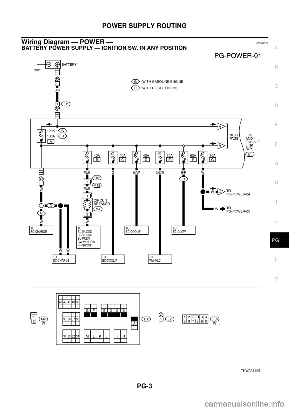
Wiring Diagram — POWER —EKS00323
BATTERY POWER SUPPLY — IGNITION SW. IN ANY POSITION
TKWA0120E
Page 2680 of 3066
PG-4
POWER SUPPLY ROUTING
TKWA0121E