check oil NISSAN X-TRAIL 2003 Electronic Repair Manual
[x] Cancel search | Manufacturer: NISSAN, Model Year: 2003, Model line: X-TRAIL, Model: NISSAN X-TRAIL 2003Pages: 3066, PDF Size: 51.47 MB
Page 2858 of 3066
RSU-6
REAR SUSPENSION ASSEMBLY
On-Vehicle Inspection and Service
EES0007F
Check axle and suspension parts for excessive play, wear, and damage.
lMove rear wheels (RH/LH) to check abnormal free play.
lRetighten all nuts and bolts to the specified torque.
lCheck strut for oil leakage and damage.
Wheel AlignmentEES0007G
DESCRIPTION
lMeasure wheel alignment under unladen conditions. “Unladen conditions” means that fuel, coolant, and
lubricant are full. However, spare tire, jack, and hand tools should be unloaded.
PRELIMINARY INSPECTION
1. Check the tires for improper air pressure and wear.
2. Check road wheels for runout.
3. Check wheel bearing axial endplay.
4. Check strut operation.
5. Check each mounting point of axle and suspension for looseness and deformation.
6. Check each link and arm for cracks, deformation, and other damage.
7. Check the vehicle posture.
CAMBER
Camber is preset at factory and cannot be adjusted.
lIf the camber is not within specification, inspect and replace any damaged or worn rear suspension parts.
TOE-IN
Measure toe-in using the following procedure.
lAlways perform following procedure on a flat surface.
lMake sure that no person is in front of the vehicle before push-
ing it.
1. Bounce rear of vehicle up and down to stabilize the posture.
2. Push the vehicle straight ahead about 5 m (16 ft).
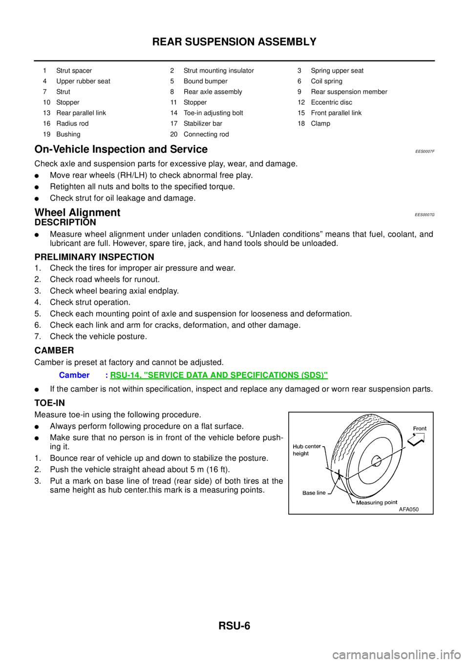
3. Put a mark on base line of tread (rear side) of both tires at the
same height as hub center.this mark is a measuring points.
1 Strut spacer 2 Strut mounting insulator 3 Spring upper seat
4 Upper rubber seat 5 Bound bumper 6 Coil spring
7 Strut 8 Rear axle assembly 9 Rear suspension member
10 Stopper 11 Stopper 12 Eccentric disc
13 Rear parallel link 14 Toe-in adjusting bolt 15 Front parallel link
16 Radius rod 17 Stabilizer bar 18 Clamp
19 Bushing 20 Connecting rod
Camber :RSU-14, "SERVICE DATA AND SPECIFICATIONS (SDS)"
AFA050
Page 2860 of 3066
RSU-8
COIL SPRING AND STRUT
COIL SPRING AND STRUT
PFP:55302
Removal and InstallationEES0007H
REMOVAL
1. Remove tires.
2. Remove brake hose lock plate and remove brake hose from strut.
3. Remove mounting nuts and washers on upper portion of stabilizer connecting rod.
4. Remove strut-to-axle housing mounting bolts and nuts.
5. Remove luggage side lower finisher in luggage compartment.Remove mounting nuts on upper portion of
strut. Then remove strut from vehicle.
INSTALLATION
lRefer toRSU-5, "Components"for tightening torque. Install in the reverse order of removal.
Disassembly and AssemblyEES0007I
DISASSEMBLY
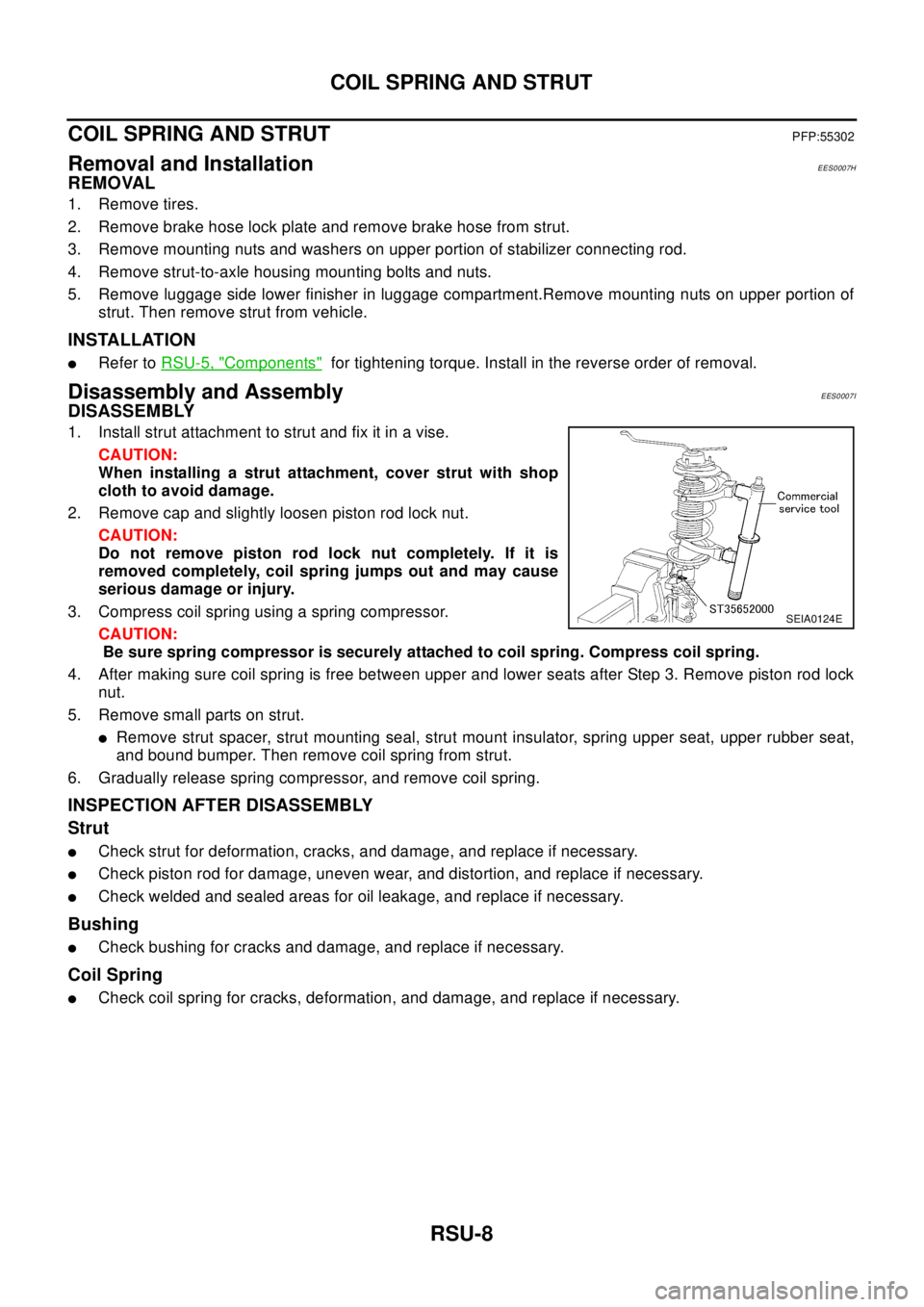
1. Install strut attachment to strut and fix it in a vise.
CAUTION:
When installing a strut attachment, cover strut with shop
cloth to avoid damage.
2. Remove cap and slightly loosen piston rod lock nut.
CAUTION:
Do not remove piston rod lock nut completely. If it is
removed completely, coil spring jumps out and may cause
serious damage or injury.
3. Compress coil spring using a spring compressor.
CAUTION:
Be sure spring compressor is securely attached to coil spring. Compress coil spring.
4. After making sure coil spring is free between upper and lower seats after Step 3. Remove piston rod lock
nut.
5. Remove small parts on strut.
lRemove strut spacer, strut mounting seal, strut mount insulator, spring upper seat, upper rubber seat,
and bound bumper. Then remove coil spring from strut.
6. Gradually release spring compressor, and remove coil spring.
INSPECTION AFTER DISASSEMBLY
Strut
lCheck strut for deformation, cracks, and damage, and replace if necessary.
lCheck piston rod for damage, uneven wear, and distortion, and replace if necessary.
lCheck welded and sealed areas for oil leakage, and replace if necessary.
Bushing
lCheck bushing for cracks and damage, and replace if necessary.
Coil Spring
lCheck coil spring for cracks, deformation, and damage, and replace if necessary.
SEIA0124E
Page 2868 of 3066
SB-2
PRECAUTIONS
PRECAUTIONS
PFP:00001
Supplemental Restraint System (SRS) “AIR BAG” and “SEAT BELT PRE-TEN-
SIONER”
EHS000BD
The Supplemental Restraint System such as “AIR BAG” and “SEAT BELT PRE-TENSIONER” used along with
a front seat belt, helps to reduce the risk or severity of injury to the driver and front passenger for certain types
of collision.
WAR NIN G:
lTo avoid rendering the SRS inoperative, which could increase the risk of personal injury or death
in the event of a collision which would result in air bag inflation, all maintenance should be per-
formed by an authorized NISSAN /INFINITI dealer.
lImproper maintenance, including incorrect removal and installation of the SRS, can lead to per-
sonal injury caused by unintentional activation of the system.
lDo not use electrical test equipment on any circuit related to the SRS unless instructed to in this
Service Manual. SRS wiring harnesses can be identified by yellow harness connector.
Precaution for Seat Belt ServiceEHS000BE
CAUTION:
lBefore removing the seat belt pre-tensioner assembly, turn the ignition switch off, disconnect the
battery ground cable and wait at least 3 minutes.
lDo not use electrical test equipment for seat belt pre-tensioner connector.
lAfter replacing or reinstalling seat belt pre-tensioner assembly, or reconnecting seat belt pre-ten-
sioner connector, check the system function. Refer toSRS-15, "
SRS Operation Check".
lDo not use disassemble buckle or seat belt assembly.
lReplace anchor bolts if they are deformed or worn out.
lNever oil tongue and buckle.
lIf any component of seat belt assembly is questionable, do not repair. Replace the whole seat belt
assembly.
lIf webbing is cut, frayed, or damaged, replace seat belt assembly.
lWhen replacing seat belt assembly, use a genuine seat belt assembly.
AFTER A COLLISION
WAR NIN G:
Inspect all seat belt assemblies including retractors and attaching hardware after any collision.
NISSAN recommends that all seat belt assemblies in use during a collision be replaced unless the col-
lision was minor and the belts show no damage and continue to operate properly. Failure to do so
could result in serious personal injury in an accident. Seat belt assemblies not in use during a colli-
sion should also be replaced if either damage or improper operation is noted. Seat belt pre-tensioner
should be replaced even if the seat belts are not in use during a frontal collision in which the air bags
are deployed.
Replace any seat belt assembly (including anchor bolts) if:
lThe seat belt was in use at the time of a collision (except for minor collisions and the belts, retractors and
buckles show no damage and continue to operate properly).
lThe seat belt was damaged in an accident. (i.e. torn webbing, bent retractor or guide, etc.)
lThe seat belt attaching point was damaged in an accident. Inspect the seat belt attaching area for damage
or distortion and repair as necessary before installing a new seat belt assembly.
lAnchor bolts are deformed or worn out.
lThe seat belt pre-tensioner should be replaced even if the seat belts are not in use during the collision in
which the air bags are deployed.
Page 2886 of 3066
SC-14
CHARGING SYSTEM
Trouble Diagnoses
EKS00319
Before conducting an alternator test, make sure that the battery is fully charged. A 30-volt voltmeter and suit-
able test probes are necessary for the test. The alternator can be checked easily by referring to the Inspection
Table.
lBefore starting, inspect the fusible link.
lUse fully charged battery.
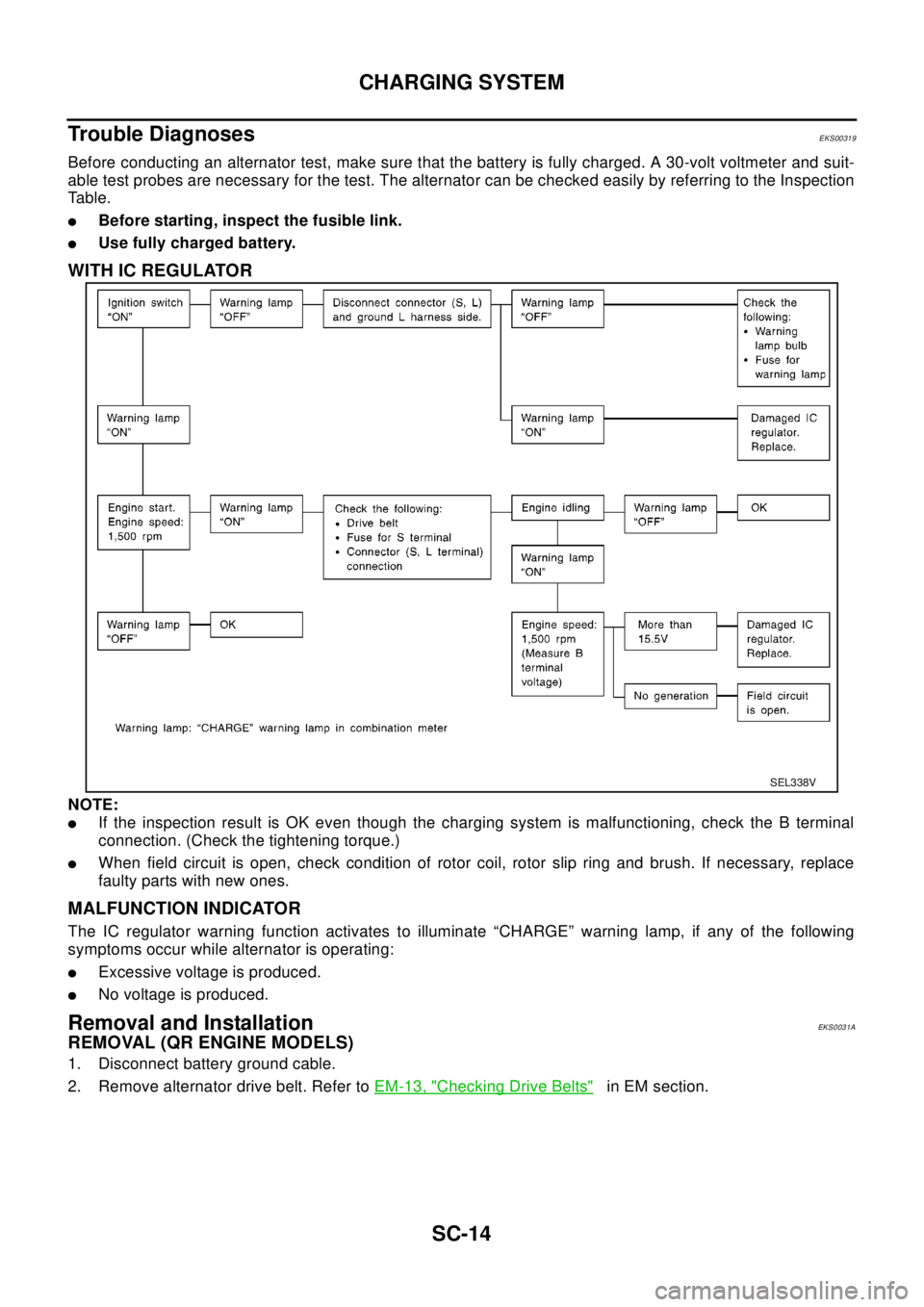
WITH IC REGULATOR
NOTE:
lIf the inspection result is OK even though the charging system is malfunctioning, check the B terminal
connection. (Check the tightening torque.)
lWhen field circuit is open, check condition of rotor coil, rotor slip ring and brush. If necessary, replace
faulty parts with new ones.
MALFUNCTION INDICATOR
The IC regulator warning function activates to illuminate “CHARGE” warning lamp, if any of the following
symptoms occur while alternator is operating:
lExcessive voltage is produced.
lNo voltage is produced.
Removal and InstallationEKS0031A
REMOVAL (QR ENGINE MODELS)
1. Disconnect battery ground cable.
2. Remove alternator drive belt. Refer toEM-13, "
Checking Drive Belts"in EM section.
SEL338V
Page 2950 of 3066
SRS-28
DRIVER AIR BAG MODULE
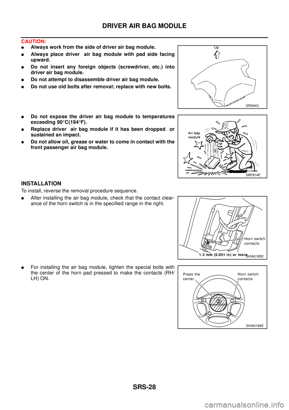
CAUTION:
lAlways work from the side of driver air bag module.
lAlways place driver air bag module with pad side facing
upward.
lDo not insert any foreign objects (screwdriver, etc.) into
driver air bag module.
lDo not attempt to disassemble driver air bag module.
lDo not use old bolts after removal; replace with new bolts.
lDo not expose the driver air bag module to temperatures
exceeding 90°C(194°F).
lReplace driver air bag module if it has been dropped or
sustained an impact.
lDo not allow oil, grease or water to come in contact with the
front passenger air bag module.
INSTALLATION
To install, reverse the removal procedure sequence.
lAfter installing the air bag module, check that the contact clear-
ance of the horn switch is in the specified range in the right.
lFor installing the air bag module, tighten the special bolts with
the center of the horn pad pressed to make the contacts (RH/
LH) ON.
SRS443
SBF814E
SHIA0185E
SHIA0184E
Page 2952 of 3066
SRS-30
DRIVER AIR BAG MODULE
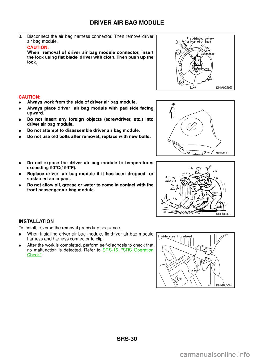
3. Disconnect the air bag harness connector. Then remove driver
air bag module.
CAUTION:
When removal of driver air bag module connector, insert
the lock using flat blade driver with cloth. Then push up the
lock,
CAUTION:
lAlways work from the side of driver air bag module.
lAlways place driver air bag module with pad side facing
upward.
lDo not insert any foreign objects (screwdriver, etc.) into
driver air bag module.
lDo not attempt to disassemble driver air bag module.
lDo not use old bolts after removal; replace with new bolts.
lDo not expose the driver air bag module to temperatures
exceeding 90°C(194°F).
lReplace driver air bag module if it has been dropped or
sustained an impact.
lDo not allow oil, grease or water to come in contact with the
front passenger air bag module.
INSTALLATION
To install, reverse the removal procedure sequence.
lWhen installing driver air bag module, fix driver air bag module
harness and harness connector to clip.
lAfter the work is completed, perform self-diagnosis to check that
no malfunction is detected. Refer toSRS-15, "
SRS Operation
Check".
SHIA0239E
SRS619
SBF814E
PHIA0023E
Page 2973 of 3066
PRECAUTIONS
TF-3
C
E
F
G
H
I
J
K
L
MA
B
TF
PRECAUTIONSPFP:00001
CautionEDS0004O
lDo not reuse the drained transfer oil.
lCheck the oil level with the vehicle on the level ground.
lDuring removal and installation, be careful not to allow foreign material such as dust or dirt to enter into
the transfer unit.
lBefore starting diagnosis of the vehicle, understand trouble symptoms well. Perform correct and system-
atic operations.
lCheck for the correct installation status prior to removal or disassembly. If mating marks are required, be
certain they do not interfere with the function of the parts they are applied to.
lCarry out the work in a clean work place. Using a dustproof room is recommended.
lBefore disassembly, using steam or white gasoline, completely remove sand and mud from the exterior of
the unit, preventing them from entering into the unit during disassembly or assembly.
lCheck appearance of the disassembled parts for damage, deformation, and abnormal wear. If a malfunc-
tion is detected, replace it with a new one.
lNormally replace O-rings, oil seals, bearings, and lock nuts with new ones every time they are removed.
lIn principle, tighten bolts or nuts gradually in several steps working diagonally from inside to outside. If
tightening sequence is specified, observe it.
lClean and flush the parts sufficiently and blow them dry.
lBe careful not to damage sliding surfaces and mating surfaces.
lAlways use shop paper for cleaning the inside of components.
lDo not use cotton gloves or a shop cloth. Using them may leave lint on the surface of the parts.
lDuring assembly always tighten bolts and screws to specified torque. new transfer oil a petroleum jelly
such as "Vaseline", or multi-purpose grease as appropriate.
lDiscard waste oil after oil changes or part treatment in accordance with local laws and regulations.
Page 2977 of 3066
NOISE, VIBRATION, AND HARSHNESS (NVH) TROUBLESHOOTING
TF-7
C
E
F
G
H
I
J
K
L
MA
B
TF
NOISE, VIBRATION, AND HARSHNESS (NVH) TROUBLESHOOTINGPFP:00003
NVH Troubleshooting ChartEDS000I4
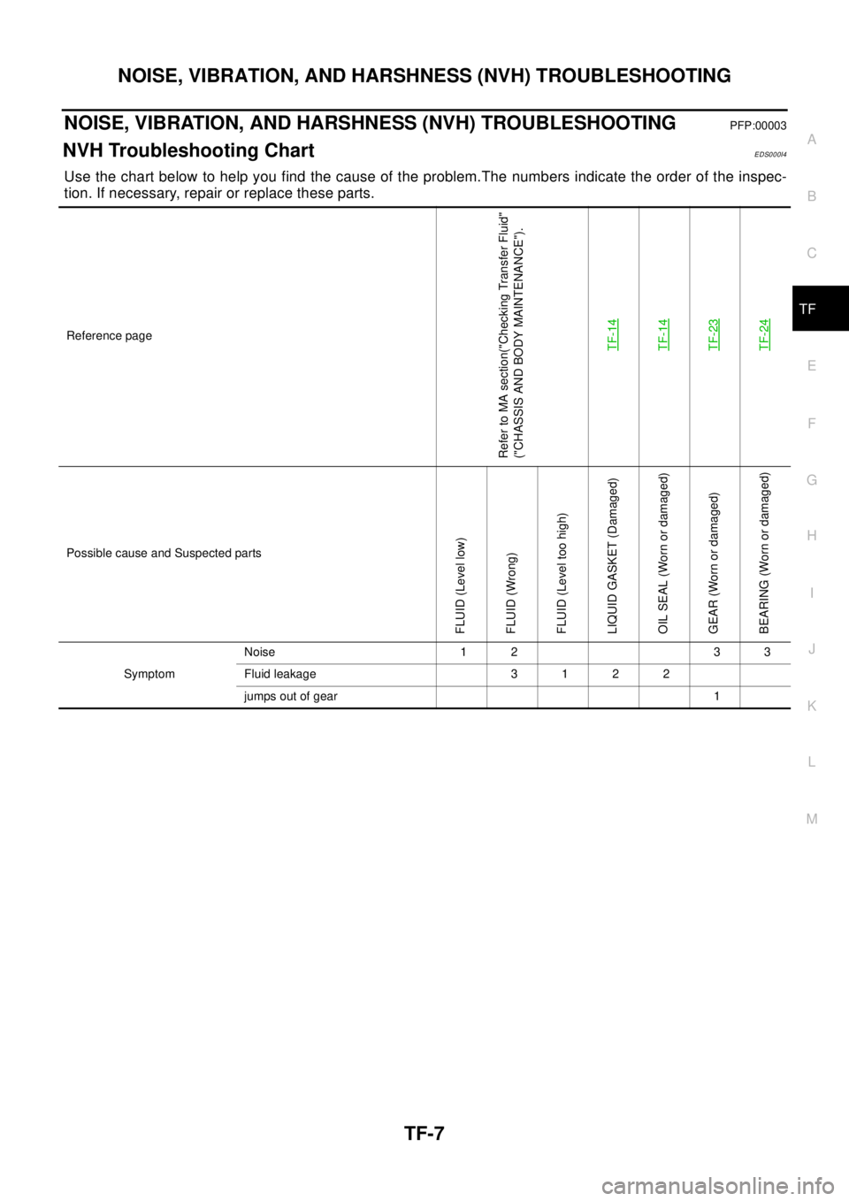
Use the chart below to help you find the cause of the problem.The numbers indicate the order of the inspec-
tion. If necessary, repair or replace these parts.
Reference page
Refer to MA section("Checking Transfer Fluid"
("CHASSIS AND BODY MAINTENANCE").
TF-14
TF-14TF-23TF-24
Possible cause and Suspected parts
FLUID (Level low)
FLUID (Wrong)
FLUID (Level too high)
LIQUID GASKET (Damaged)
OIL SEAL (Worn or damaged)
GEAR (Worn or damaged)
BEARING (Worn or damaged)
SymptomNoise 1 2 3 3
Fluidleakage 3122
jumps out of gear 1
Page 2978 of 3066
TF-8
TRANSFER FLUID
TRANSFER FLUID
PFP:KLD30
ReplacementEDS0004Q
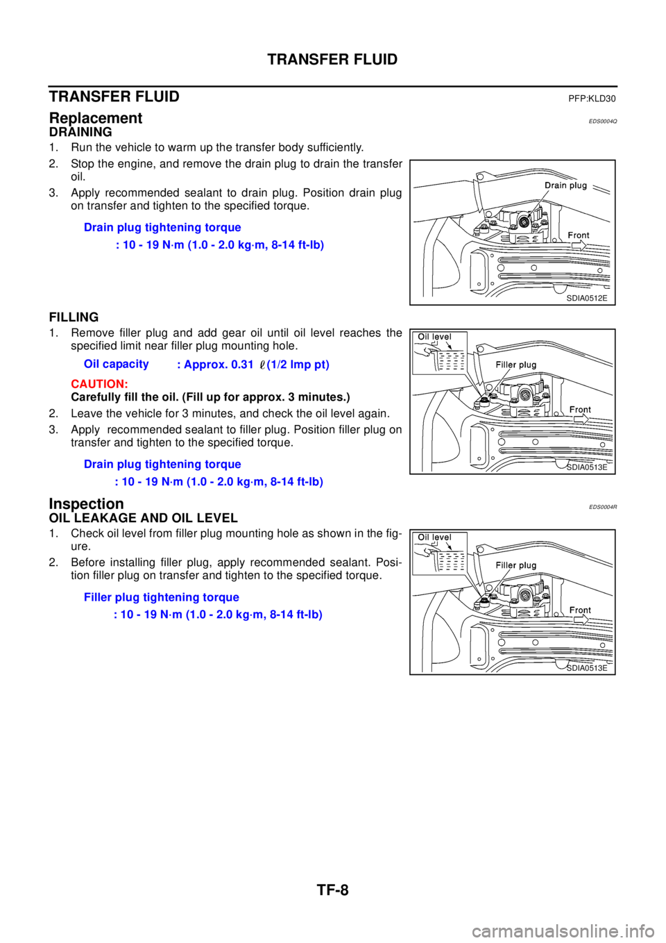
DRAINING
1. Run the vehicle to warm up the transfer body sufficiently.
2. Stop the engine, and remove the drain plug to drain the transfer
oil.
3. Apply recommended sealant to drain plug. Position drain plug
on transfer and tighten to the specified torque.
FILLING
1. Remove filler plug and add gear oil until oil level reaches the
specified limit near filler plug mounting hole.
CAUTION:
Carefully fill the oil. (Fill up for approx. 3 minutes.)
2. Leave the vehicle for 3 minutes, and check the oil level again.
3. Apply recommended sealant to filler plug. Position filler plug on
transfer and tighten to the specified torque.
InspectionEDS0004R
OIL LEAKAGE AND OIL LEVEL
1. Check oil level from filler plug mounting hole as shown in the fig-
ure.
2. Before installing filler plug, apply recommended sealant. Posi-
tion filler plug on transfer and tighten to the specified torque.Drain plug tightening torque
: 10 - 19 N·m (1.0 - 2.0 kg·m, 8-14 ft-lb)
SDIA0512E
Oil capacity
: Approx. 0.31 (1/2 lmp pt)
Drain plug tightening torque
: 10 - 19 N·m (1.0 - 2.0 kg·m, 8-14 ft-lb)
SDIA0513E
Filler plug tightening torque
:10-19N·m(1.0-2.0kg·m,8-14ft-lb)
SDIA0513E
Page 2979 of 3066
SIDE OIL SEAL
TF-9
C
E
F
G
H
I
J
K
L
MA
B
TF
SIDE OIL SEALPFP:33142
Removal and InstallationEDS0004S
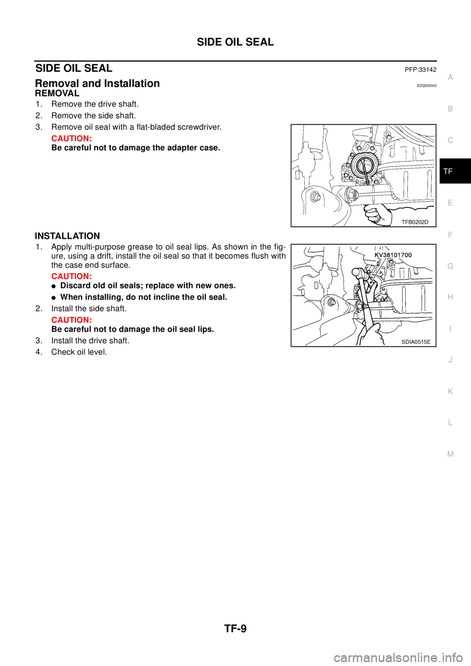
REMOVAL
1. Remove the drive shaft.
2. Remove the side shaft.
3. Remove oil seal with a flat-bladed screwdriver.
CAUTION:
Be careful not to damage the adapter case.
INSTALLATION
1. Apply multi-purpose grease to oil seal lips. As shown in the fig-
ure, using a drift, install the oil seal so that it becomes flush with
the case end surface.
CAUTION:
lDiscard old oil seals; replace with new ones.
lWhen installing, do not incline the oil seal.
2. Install the side shaft.
CAUTION:
Be careful not to damage the oil seal lips.
3. Install the drive shaft.
4. Check oil level.
TFB0202D
SDIA0515E