bulb NISSAN X-TRAIL 2003 Electronic Owner's Manual
[x] Cancel search | Manufacturer: NISSAN, Model Year: 2003, Model line: X-TRAIL, Model: NISSAN X-TRAIL 2003Pages: 3066, PDF Size: 51.47 MB
Page 2406 of 3066
LT-8
HEADLAMP
Bulb Replacement
EKS003CH
HEAD LAMP
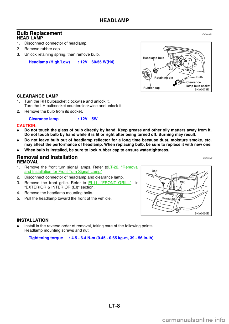
1. Disconnect connector of headlamp.
2. Remove rubber cap.
3. Unlock retaining spring, then remove bulb.
CLEARANCE LAMP
1. Turn the RH bulbsocket clockwise and unlock it.
Turn the LH bulbsocket counterclockwise and unlock it.
2. Remove the bulb from its socket.
CAUTION:
lDo not touch the glass of bulb directly by hand. Keep grease and other oily matters away from it.
Do not touch bulb by hand while it is lit or right after being turned off. Burning may result.
lDo not leave bulb out of headlamp reflector for a long time because dust, moisture smoke, etc.
may affect the performance of headlamp. When replacing bulb, be sure to replace it with new one.
lWhen bulb is installed, be sure to lock rubber cap to ensure watertightness.
Removal and InstallationEKS003CI
REMOVAL
1. Remove the front turn signal lamps. Refer toLT-22, "Removal
and Installation for Front Turn Signal Lamp"
2. Disconnect connector of headlamp and clearance lamp.
3. Remove the front grille. Refer toEI-11, "
FRONT GRILL"in
"EXTERIOR & INTERIOR (EI)" section.
4. Remove the headlamp mounting bolts.
5. Pull the headlamp toward the front of the vehicle.
INSTALLATION
lInstall in the reverse order of removal, taking care of the following points.
Headlamp mounting screws and nutHeadlamp (High/Low) : 12V 60/55 W(H4)
SKIA0073E
Clearance lamp : 12V 5W
SKIA0050E
Tightening torque : 4.5 - 6.4 N-m (0.45 - 0.65 kg-m, 39 - 56 in-lb)
Page 2412 of 3066

LT-14
HEADLAMP - DAYTIME LIGHT SYSTEM -
Trouble Diagnoses
EKS003CO
DAYTIME LIGHT UNIT INSPECTION TABLE
*: Daytime light operating: Lighting switch in “OFF” position with engine running.
Bulb ReplacementEKS003CP
Refer toLT- 4 , "HEADLAMP"
Aiming AdjustmentEKS003BE
Refer toLT- 4 , "HEADLAMP"
Te r m i n a l
No.WIRE
COLORConnectionsINPUT (I)/
OUTPUT
(O)Operated conditionVo l ta g e (V )
(Approximate val-
ues)
1G/WPower source for illumi-
nation & tail lamp—— 12
2LGPower source for head-
lamp LH—— 12
3R/WPower source for head-
lamp RH—— 12
4G/YHeadlampRH OON (daytime light operating*) 12
OFF 0
5Y/GHeadlampLH OON (daytime light operating*) 12
OFF 0
6 B/Y Start signal I Ignition switchSTART 12
ON, ACC or OFF 0
7 BR Power source — Ignition switchON or START 12
ACC or OFF 0
8 Y/R Alternator “L” terminal I EngineRunning 12
Stopped 0
9 B Ground — — —
10 R/L Illumination & tail lamp OON (daytime light operating*) 12
OFF 0
11 R/L Lighting switch I1ST·2ND position 12
OFF 0
Page 2419 of 3066
TURN SIGNAL AND HAZARD WARNING LAMPS
LT-21
C
D
E
F
G
H
I
J
L
MA
B
LT
Trouble DiagnosesEKS003BG
Electrical Components InspectionEKS0034C
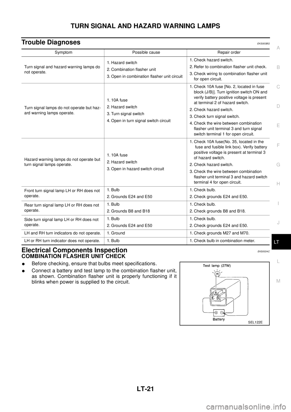
COMBINATION FLASHER UNIT CHECK
lBefore checking, ensure that bulbs meet specifications.
lConnect a battery and test lamp to the combination flasher unit,
as shown. Combination flasher unit is properly functioning if it
blinks when power is supplied to the circuit.
Symptom Possible cause Repair order
Turn signal and hazard warning lamps do
not operate.1. Hazard switch
2. Combination flasher unit
3. Open in combination flasher unit circuit1. Check hazard switch.
2. Refer to combination flasher unit check.
3. Check wiring to combination flasher unit
for open circuit.
Turn signal lamps do not operate but haz-
ard warning lamps operate.1. 10A fuse
2. Hazard switch
3. Turn signal switch
4. Open in turn signal switch circuit1. Check 10A fuse [No. 2, located in fuse
block (J/B)]. Turn ignition switch ON and
verify battery positive voltage is present
at terminal 2 of hazard switch.
2. Check hazard switch.
3. Check turn signal switch.
4. Check the wire between combination
flasher unit terminal 3 and turn signal
switch terminal 1 for open circuit.
Hazard warning lamps do not operate but
turn signal lamps operate.1. 10A fuse
2. Hazard switch
3. Open in hazard switch circuit1. Check 10A fuse(No. 35, located in the
fuse and fusible link box). Verify battery
positive voltage is present at terminal 3
of hazard switch.
2. Check hazard switch.
3. Check the wire between combination
flasher unit terminal 3 and hazard switch
terminal 4 for open circuit.
Front turn signal lamp LH or RH does not
operate.1. Bulb
2. Grounds E24 and E501. Check bulb.
2. Check grounds E24 and E50.
Rear turn signal lamp LH or RH does not
operate.1. Bulb
2. Grounds B8 and B181. Check bulb.
2. Check grounds B8 and B18.
Side turn signal lamp LH or RH does not
operate.1. Bulb
2. Grounds E24 and E501. Check bulb.
2. Check grounds E24 and E50.
LH and RH turn indicators do not operate. 1. Ground 1. Check grounds M27 and M70.
LH or RH turn indicator does not operate. 1. Bulb 1. Check bulb in combination meter.
SEL122E
Page 2420 of 3066
LT-22
TURN SIGNAL AND HAZARD WARNING LAMPS
Bulb Replacement
EKS0034D
FRONT TURN SIGNAL LAMP
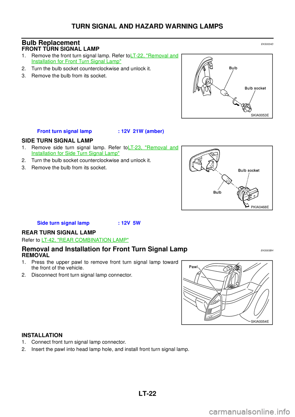
1. Remove the front turn signal lamp. Refer toLT- 2 2 , "Removal and
Installation for Front Turn Signal Lamp"
2. Turn the bulb socket counterclockwise and unlock it.
3. Remove the bulb from its socket.
SIDE TURN SIGNAL LAMP
1. Remove side turn signal lamp. Refer toLT- 2 3 , "Removal and
Installation for Side Turn Signal Lamp"
2. Turn the bulb socket counterclockwise and unlock it.
3. Remove the bulb from its socket.
REAR TURN SIGNAL LAMP
Refer toLT- 4 2 , "REAR COMBINATION LAMP"
Removal and Installation for Front Turn Signal LampEKS003BH
REMOVAL
1. Press the upper pawl to remove front turn signal lamp toward
the front of the vehicle.
2. Disconnect front turn signal lamp connector.
INSTALLATION
1. Connect front turn signal lamp connector.
2. Insert the pawl into head lamp hole, and install front turn signal lamp.
SKIA0053E
Front turn signal lamp : 12V 21W (amber)
PKIA0468E
Side turn signal lamp : 12V 5W
SKIA0054E
Page 2425 of 3066

STOP LAMP
LT-27
C
D
E
F
G
H
I
J
L
MA
B
LT
Bulb ReplacementEKS0034K
STOP LAMP
Refer toLT- 4 2 , "REAR COMBINATION LAMP"
HIGH-MOUNTED STOP LAMP
1. Remove the high-mounted stop lamp cover. Refer toLT- 2 7 ,
"HIGH-MOUNTED STOP LAMP"in “Removal and Installation”.
2. Turn the high-mounted stop lamp bulb socket counterclockwise
and unlock it.
3. Remove the bulb.
Removal and InstallationEKS0034L
STOP LAMP
Refer toLT- 4 2 , "REAR COMBINATION LAMP"
HIGH-MOUNTED STOP LAMP
1. Open the backdoor. Then, pull the edge of the cover (A in the
figure below) to each side in turn downward until the pawls
inside the cover are released.
2. Pull down the cover toward under the vehicle.
3. Remove the high-mounted stop lamp mounting bolts.
4. Disconnect the high-mounted stop lamp connector and remove
from the vehicle.High-mounted Stop Lamp : 12V 5W
PKIA0496E
PKIA0497E
PKIA0498E
Page 2427 of 3066

BACK-UP LAMP
LT-29
C
D
E
F
G
H
I
J
L
MA
B
LT
Bulb ReplacementEKS003C4
Refer toLT- 4 2 , "REAR COMBINATION LAMP".
Removal and InstallationEKS003C5
Refer toLT-42, "REAR COMBINATION LAMP".
Page 2430 of 3066

LT-32
PARKING, LICENSE PLATE AND TAIL LAMPS
Bulb Replacement
EKS003C1
PARKING AND TAIL LAMPS
Refer toLT- 4 2 , "REAR COMBINATION LAMP".
LICENSE PLATE LAMP
1. Remove license plate lamp.
2. Turn bulb socket, then remove it.
Removal and InstallationEKS003C2
PARKING AND TAIL LAMPS
Refer toLT- 4 2 , "REAR COMBINATION LAMP"
LICENSE PLATE LAMP
Removal
1. Remove the license lamp finisher. Refer toEI-22, "LICENSE
LAMP FINISHER"in “EXTERIOR & INTERIOR (EI)” section.
2. Remove the harness from installation pawl for harness.
3. Remove license plate lamp mounting screws (2 each, RH and
LH).
4. Pull out license plate lamp from finisher.
Installation
lInstall license plate lamp in the reverse order of removal, observing the tightening torque shown below.
License plate lamp mounting screwsLicense plate lamp : 12 V 5 W
SKIA0055E
Tightening torque :1.0 - 1.8 N-m (0.10 - 0.19 kg-m,9-
16 in-lb)
Page 2434 of 3066
LT-36
FRONT FOG LAMP
Bulb Replacement
EKS003DI
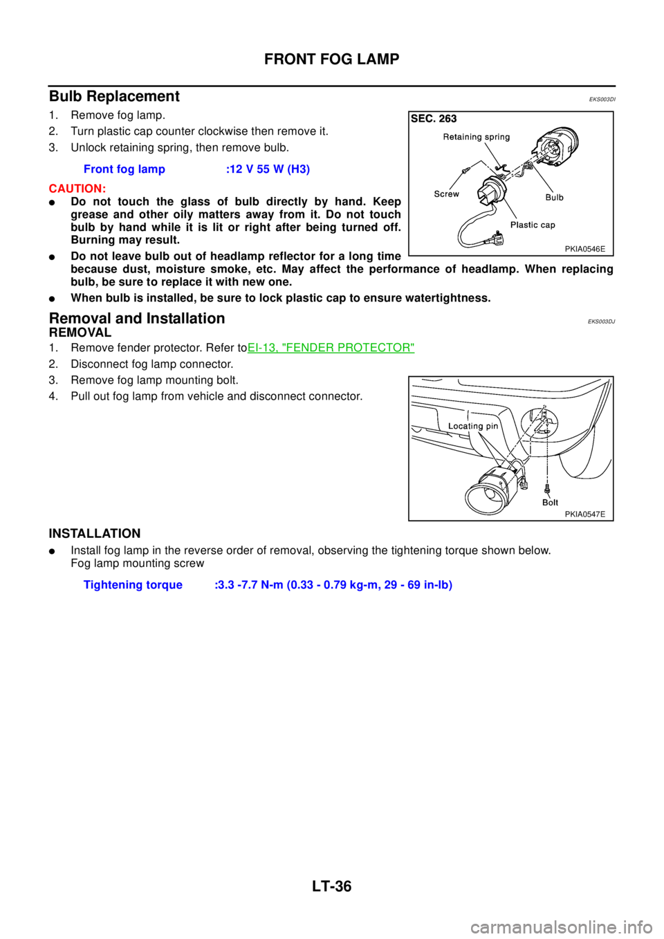
1. Remove fog lamp.
2. Turn plastic cap counter clockwise then remove it.
3. Unlock retaining spring, then remove bulb.
CAUTION:
lDo not touch the glass of bulb directly by hand. Keep
grease and other oily matters away from it. Do not touch
bulb by hand while it is lit or right after being turned off.
Burning may result.
lDo not leave bulb out of headlamp reflector for a long time
because dust, moisture smoke, etc. May affect the performance of headlamp. When replacing
bulb, be sure to replace it with new one.
lWhen bulb is installed, be sure to lock plastic cap to ensure watertightness.
Removal and InstallationEKS003DJ
REMOVAL
1. Remove fender protector. Refer toEI-13, "FENDER PROTECTOR"
2. Disconnect fog lamp connector.
3. Remove fog lamp mounting bolt.
4. Pull out fog lamp from vehicle and disconnect connector.
INSTALLATION
lInstall fog lamp in the reverse order of removal, observing the tightening torque shown below.
Fog lamp mounting screwFront fog lamp :12 V 55 W (H3)
PKIA0546E
PKIA0547E
Tightening torque :3.3 -7.7 N-m (0.33 - 0.79 kg-m, 29 - 69 in-lb)
Page 2437 of 3066
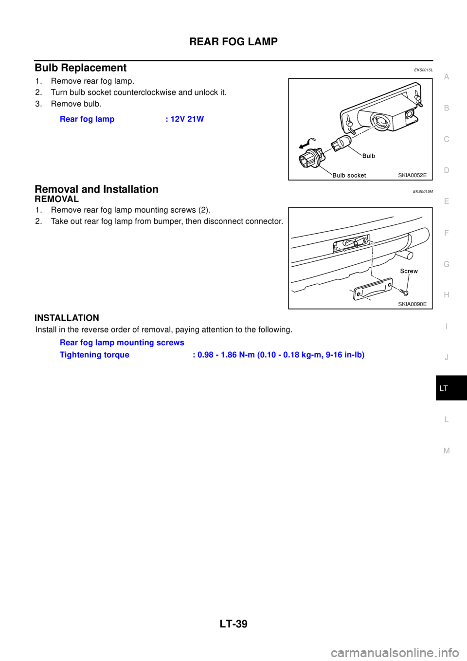
REAR FOG LAMP
LT-39
C
D
E
F
G
H
I
J
L
MA
B
LT
Bulb ReplacementEKS0015L
1. Remove rear fog lamp.
2. Turn bulb socket counterclockwise and unlock it.
3. Remove bulb.
Removal and InstallationEKS0015M
REMOVAL
1. Remove rear fog lamp mounting screws (2).
2. Take out rear fog lamp from bumper, then disconnect connector.
INSTALLATION
Install in the reverse order of removal, paying attention to the following.Rear fog lamp : 12V 21W
SKIA0052E
SKIA0090E
Rear fog lamp mounting screws
Tightening torque : 0.98 - 1.86 N-m (0.10 - 0.18 kg-m, 9-16 in-lb)
Page 2438 of 3066

LT-40
CLEARANCE LAMP/TAIL LAMP
CLEARANCE LAMP/TAIL LAMP
PFP:26010
Bulb Rplacement (Clearance Lamp)EKS001UR
Refer toLT- 4 , "HEADLAMP"
Bulb Replacement (Taillamp)EKS001US
Refer toLT- 4 2 , "REAR COMBINATION LAMP"
Removal and Installation of Clearance LampEKS001UT
Refer toLT- 4 , "HEADLAMP"
Removal and Installation of TaillampEKS001UU
Refer toLT- 4 2 , "REAR COMBINATION LAMP"