cooling NISSAN X-TRAIL 2003 Electronic Owner's Manual
[x] Cancel search | Manufacturer: NISSAN, Model Year: 2003, Model line: X-TRAIL, Model: NISSAN X-TRAIL 2003Pages: 3066, PDF Size: 51.47 MB
Page 689 of 3066
BLOWER MOTOR
ATC-111
C
D
E
F
G
H
I
K
L
MA
B
AT C
BLOWER MOTORPFP:27226
Removal and InstallationEJS000UN
1. Remove the blower unit. Refer to .ATC-109, "Removal and
Installation"
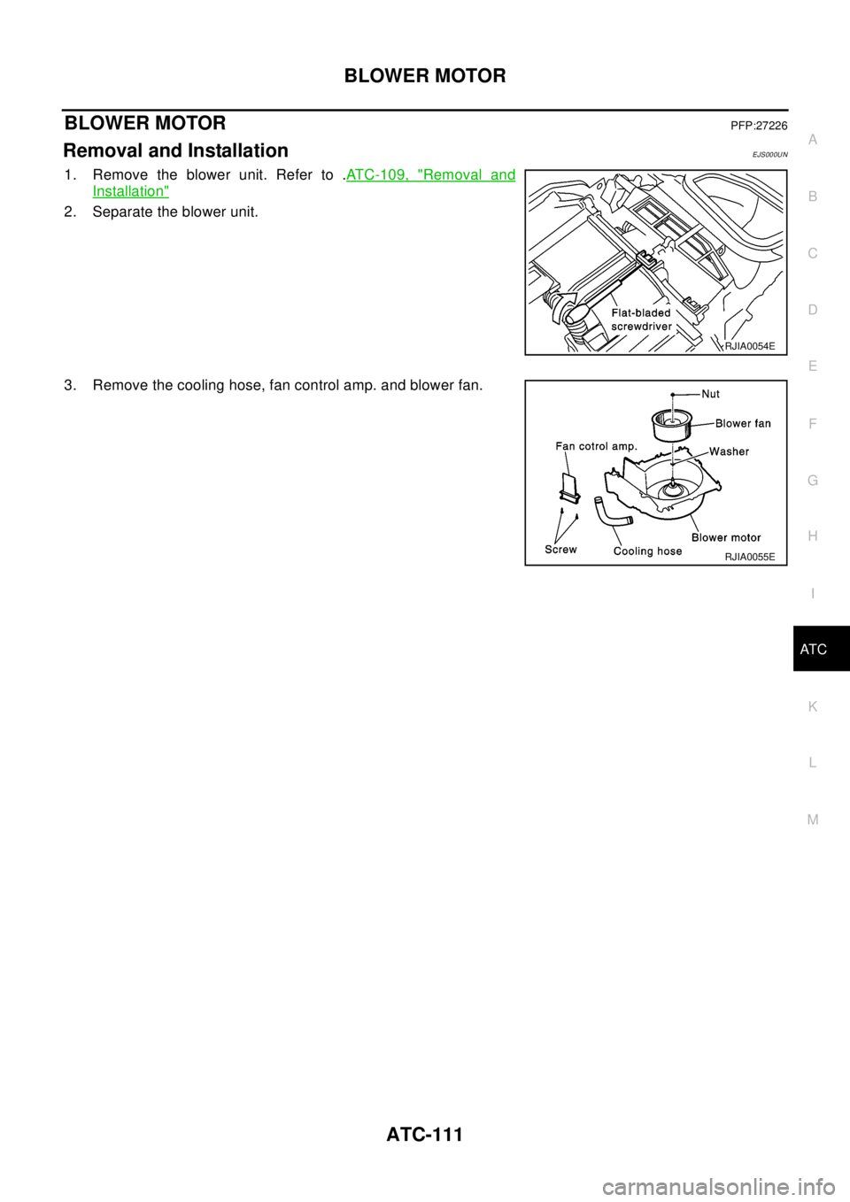
2. Separate the blower unit.
3. Remove the cooling hose, fan control amp. and blower fan.
RJIA0054E
RJIA0055E
Page 693 of 3066
HEATER & COOLING UNIT ASSEMBLY
ATC-115
C
D
E
F
G
H
I
K
L
MA
B
AT C
HEATER & COOLING UNIT ASSEMBLYPFP:27110
Removal and InstallationEJS000UT
REMOVAL
1. Discharge refrigerant from A/C system.
2. Drain coolant from cooling system. Refer toCO-9, "
Changing
Engine Coolant"QR engine;CO-30, "Changing Engine Coolant"
YD engine.
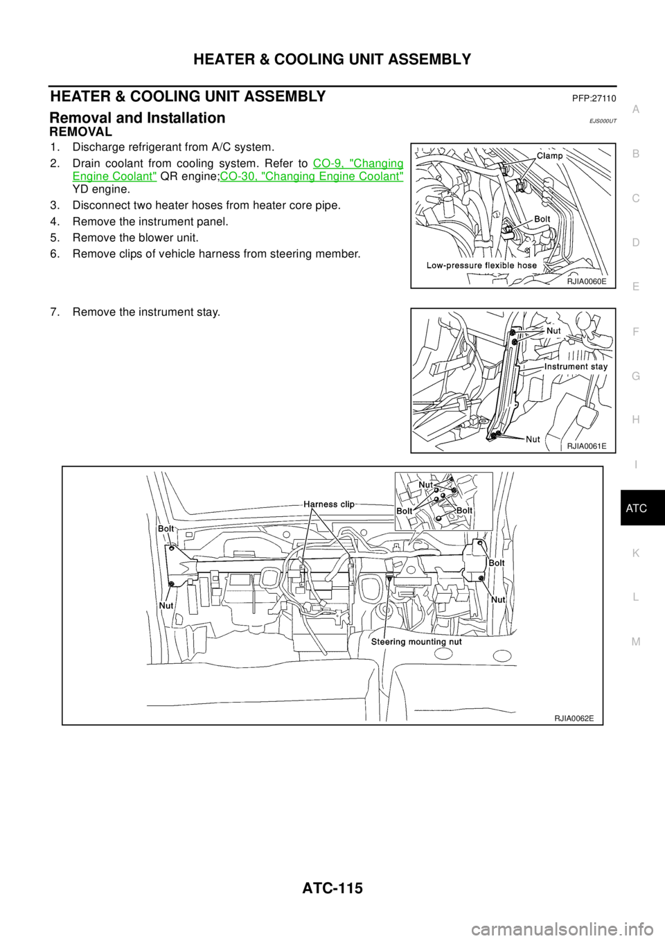
3. Disconnect two heater hoses from heater core pipe.
4. Remove the instrument panel.
5. Remove the blower unit.
6. Remove clips of vehicle harness from steering member.
7. Remove the instrument stay.
RJIA0060E
RJIA0061E
RJIA0062E
Page 694 of 3066
ATC-116
HEATER & COOLING UNIT ASSEMBLY
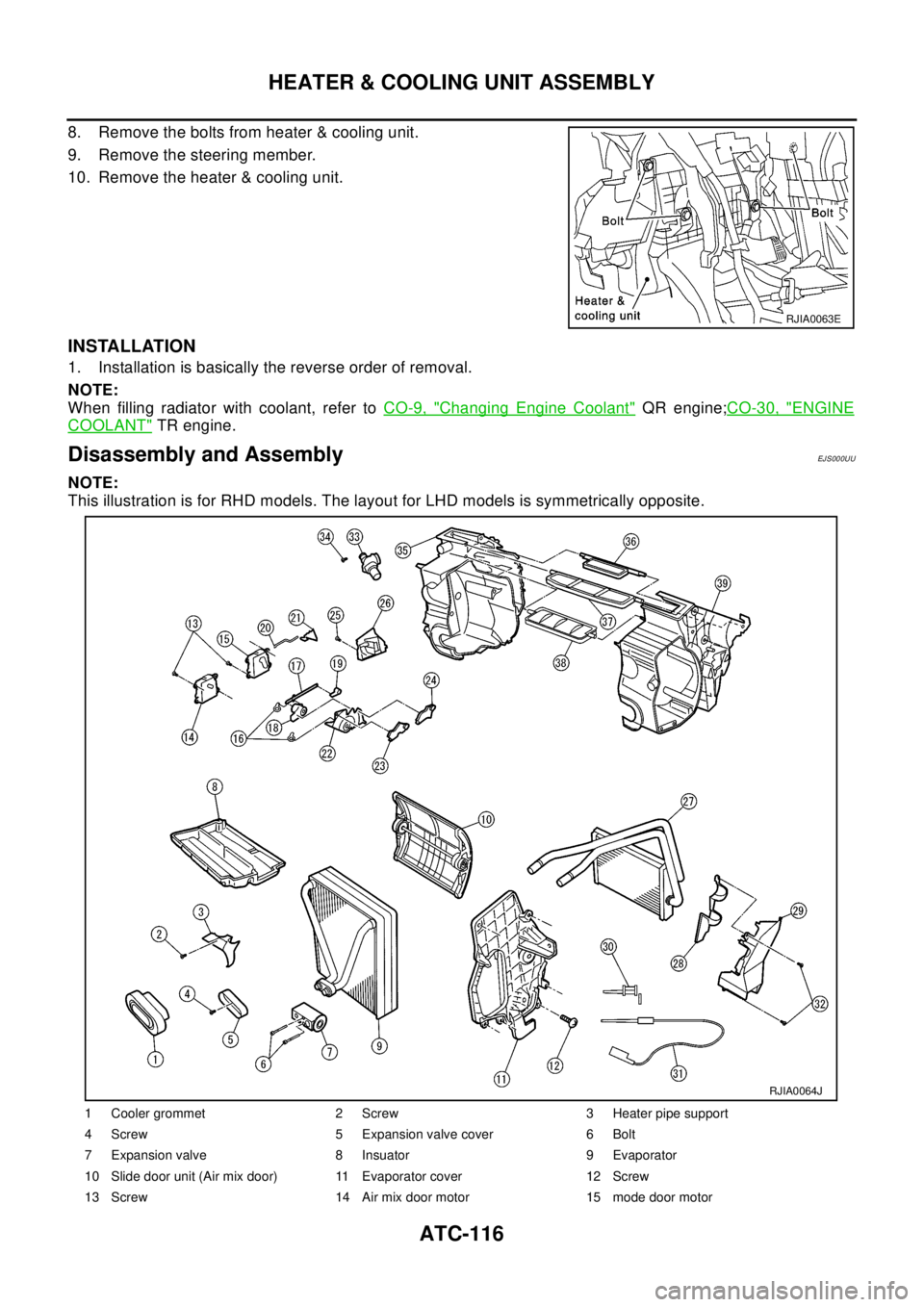
8. Remove the bolts from heater & cooling unit.
9. Remove the steering member.
10. Remove the heater & cooling unit.
INSTALLATION
1. Installation is basically the reverse order of removal.
NOTE:
When filling radiator with coolant, refer toCO-9, "
Changing Engine Coolant"QR engine;CO-30, "ENGINE
COOLANT"TR engine.
Disassembly and AssemblyEJ S00 0UU
NOTE:
This illustration is for RHD models. The layout for LHD models is symmetrically opposite.
RJIA0063E
1 Cooler grommet 2 Screw 3 Heater pipe support
4 Screw 5 Expansion valve cover 6 Bolt
7 Expansion valve 8 Insuator 9 Evaporator
10 Slide door unit (Air mix door) 11 Evaporator cover 12 Screw
13 Screw 14 Air mix door motor 15 mode door motor
RJIA0064J
Page 695 of 3066

HEATER & COOLING UNIT ASSEMBLY
ATC-117
C
D
E
F
G
H
I
K
L
MA
B
AT C
16 Screw 17 Ventilator door link 1 18 Ventilator door link 2
19 Ventilator door lever 20 Rod 21 Rod holder
22 Main link 23 Max cool door lever 24 Defroster door lever
25 Screw 26 Foot duct (right side) 27 Heater core
28 Heater core cover 29 Foot duct (left side) 30 Intake sensor bracket
31 Intake sensor 32 Screw 33 Aspirator
34 Screw 35 Heater & cooling unit case (right side) 36 Defroster door
37 Ventilator door 38 Max cool door 39 Heater & cooling unit case (left side)
Page 698 of 3066
ATC-120
HEATER CORE
HEATER CORE
PFP:27140
Removal and InstallationEJS000W0
1. Remove the heater & cooling unit. Refer to .AT C - 11 5 , "HEATER
&COOLING UNIT ASSEMBLY"
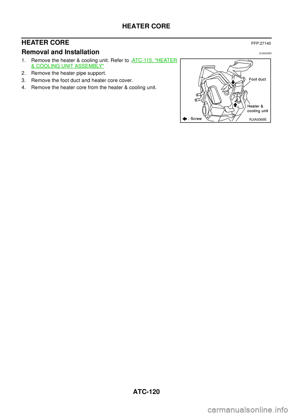
2. Remove the heater pipe support.
3. Remove the foot duct and heater core cover.
4. Remove the heater core from the heater & cooling unit.
RJIA0069E
Page 700 of 3066
ATC-122
DUCTS AND GRILLES
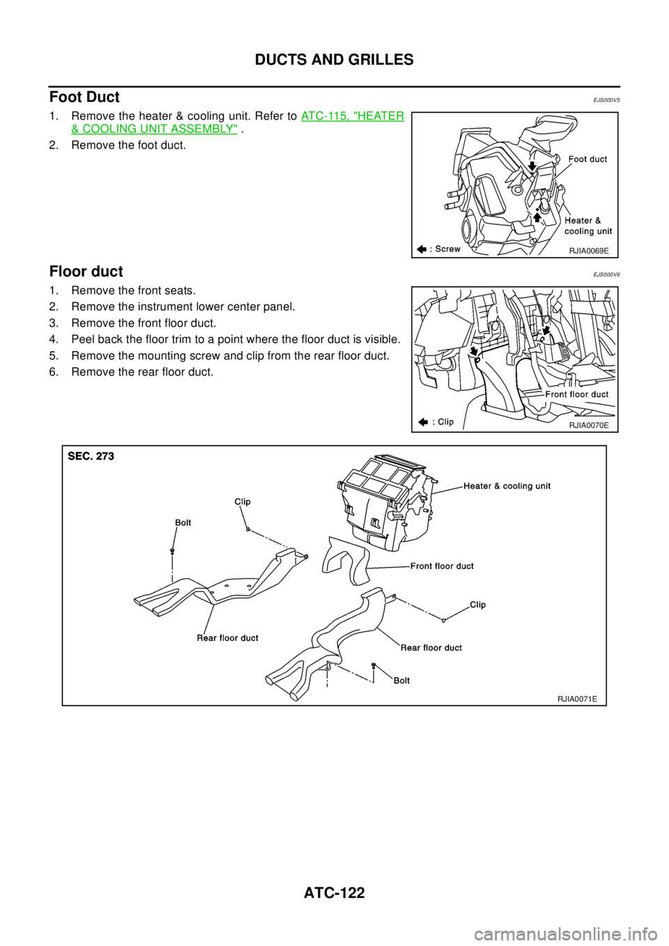
Foot Duct
EJS000V5
1. Remove the heater & cooling unit. Refer toATC-115, "HEATER
&COOLING UNIT ASSEMBLY".
2. Remove the foot duct.
Floor ductEJS000V6
1. Remove the front seats.
2. Remove the instrument lower center panel.
3. Remove the front floor duct.
4. Peel back the floor trim to a point where the floor duct is visible.
5. Remove the mounting screw and clip from the rear floor duct.
6. Remove the rear floor duct.
RJIA0069E
RJIA0070E
RJIA0071E
Page 703 of 3066
REFRIGERANT LINES
ATC-125
C
D
E
F
G
H
I
K
L
MA
B
AT C
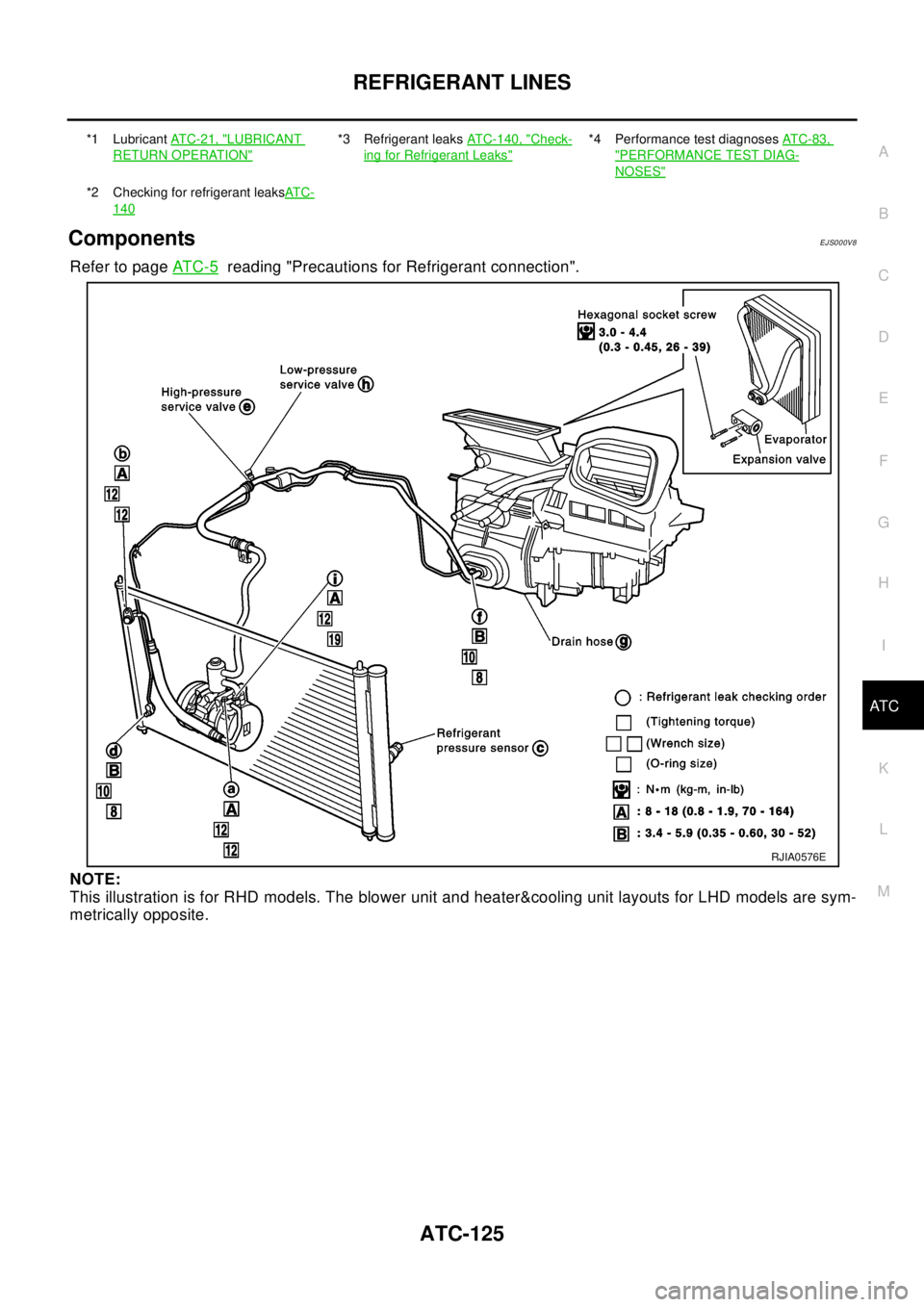
ComponentsEJS000V8
Refer to pageAT C - 5reading "Precautions for Refrigerant connection".
NOTE:
This illustration is for RHD models. The blower unit and heater&cooling unit layouts for LHD models are sym-
metrically opposite.
*1 LubricantAT C - 2 1 , "LUBRICANT
RETURN OPERATION"
*3 Refrigerant leaksATC-140, "Check-
ing for Refrigerant Leaks"
*4 Performance test diagnosesAT C - 8 3 ,
"PERFORMANCE TEST DIAG-
NOSES"
*2 Checking for refrigerant leaksAT C -
140
RJIA0576E
Page 704 of 3066
ATC-126
REFRIGERANT LINES
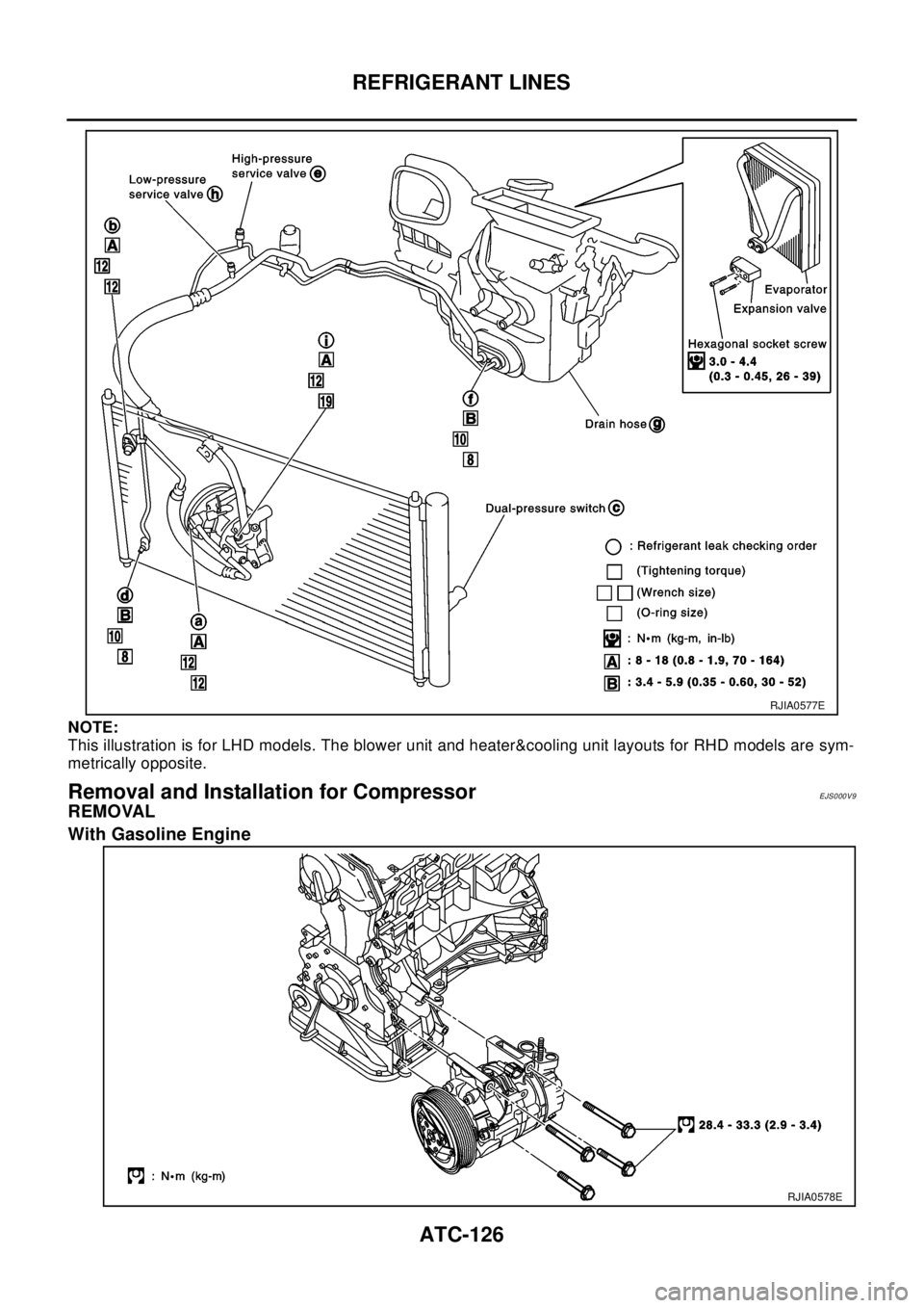
NOTE:
This illustration is for LHD models. The blower unit and heater&cooling unit layouts for RHD models are sym-
metrically opposite.
Removal and Installation for CompressorEJS000V9
REMOVAL
With Gasoline Engine
RJIA0577E
RJIA0578E
Page 717 of 3066
REFRIGERANT LINES
ATC-139
C
D
E
F
G
H
I
K
L
MA
B
AT C
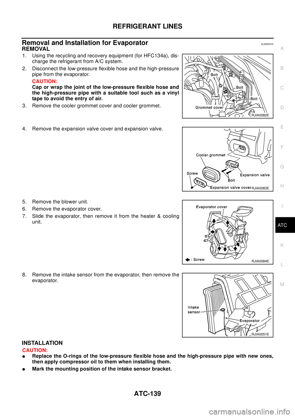
Removal and Installation for EvaporatorEJS000VG
REMOVAL
1. Using the recycling and recovery equipment (for HFC134a), dis-
charge the refrigerant from A/C system.
2. Disconnect the low-pressure flexible hose and the high-pressure
pipe from the evaporator.
CAUTION:
Cap or wrap the joint of the low-pressure flexible hose and
the high-pressure pipe with a suitable tool such as a vinyl
tape to avoid the entry of air.
3. Remove the cooler grommet cover and cooler grommet.
4. Remove the expansion valve cover and expansion valve.
5. Remove the blower unit.
6. Remove the evaporator cover.
7. Slide the evaporator, then remove it from the heater & cooling
unit.
8. Remove the intake sensor from the evaporator, then remove the
evaporator.
INSTALLATION
CAUTION:
lReplace the O-rings of the low-pressure flexible hose and the high-pressure pipe with new ones,
then apply compressor oil to them when installing them.
lMark the mounting position of the intake sensor bracket.
RJIA0082E
RJIA0083E
RJIA0084E
RJIA0051E
Page 721 of 3066
REFRIGERANT LINES
ATC-143
C
D
E
F
G
H
I
K
L
MA
B
AT C
Check all around the service valves. Ensure service valve caps are secured on the service valves (to pre-
vent leaks).
NOTE:
After removing A/C manifold gauge set from service valves, wipe any residue from valves to prevent any
false readings by leak detector.
Cooling unit (Evaporator)
With engine OFF, turn blower fan on "High" for at least 15 seconds to dissipate any refrigerant trace in the
cooling unit. Wait a minimum of 10 minutes accumulation time (refer to the manufacturer's recommended
procedure for actual wait time) before inserting the leak detector probe into the drain hose.
Keep the probe inserted for at least 10 seconds. Use caution not to contaminate the probe tip with water
or dirt that may be in the drain hose.
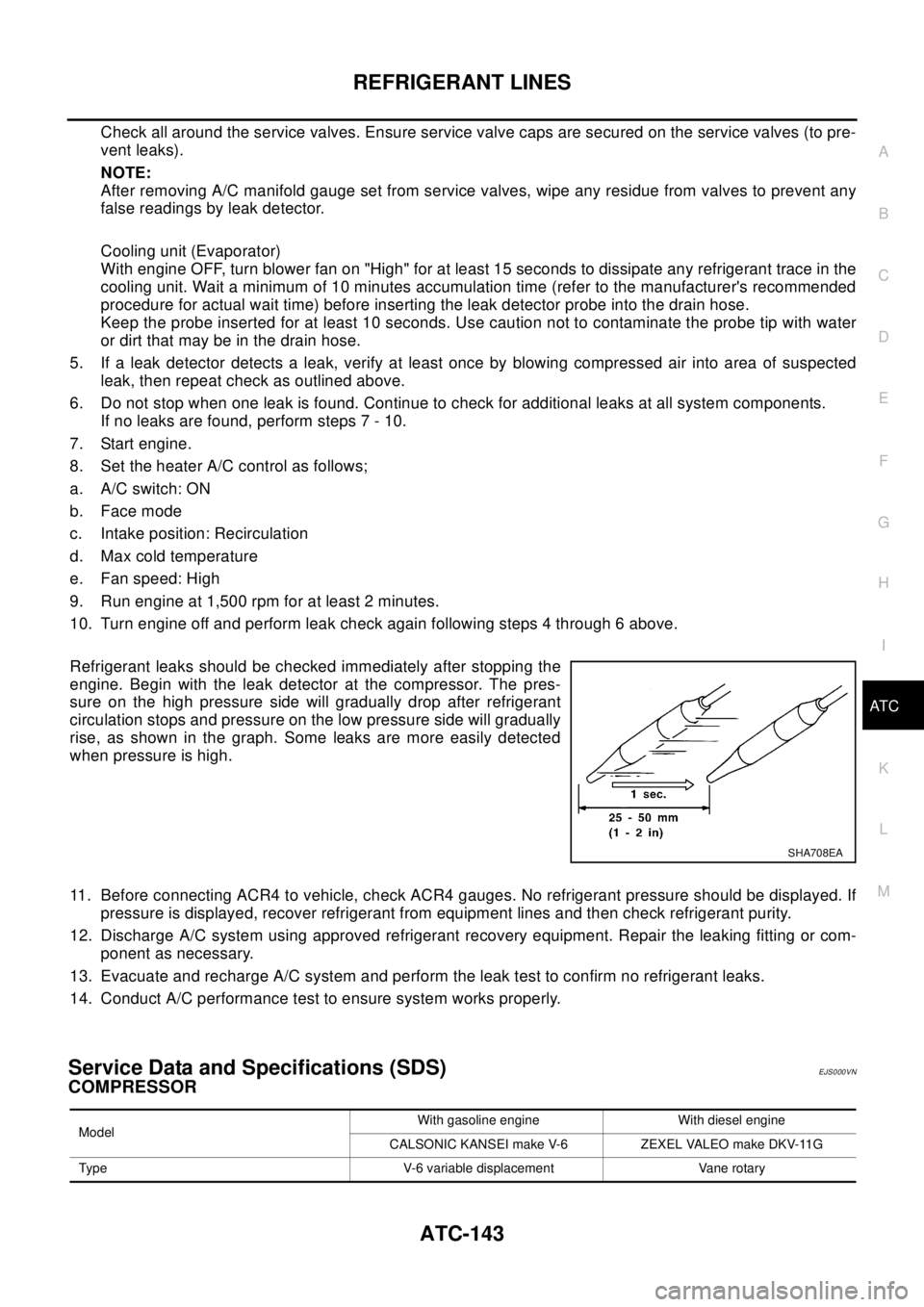
5. If a leak detector detects a leak, verify at least once by blowing compressed air into area of suspected
leak, then repeat check as outlined above.
6. Do not stop when one leak is found. Continue to check for additional leaks at all system components.
If no leaks are found, perform steps 7 - 10.
7. Start engine.
8. Set the heater A/C control as follows;
a. A/C switch: ON
b. Face mode
c. Intake position: Recirculation
d. Max cold temperature
e. Fan speed: High
9. Run engine at 1,500 rpm for at least 2 minutes.
10. Turn engine off and perform leak check again following steps 4 through 6 above.
Refrigerant leaks should be checked immediately after stopping the
engine. Begin with the leak detector at the compressor. The pres-
sure on the high pressure side will gradually drop after refrigerant
circulation stops and pressure on the low pressure side will gradually
rise, as shown in the graph. Some leaks are more easily detected
when pressure is high.
11. Before connecting ACR4 to vehicle, check ACR4 gauges. No refrigerant pressure should be displayed. If
pressure is displayed, recover refrigerant from equipment lines and then check refrigerant purity.
12. Discharge A/C system using approved refrigerant recovery equipment. Repair the leaking fitting or com-
ponent as necessary.
13. Evacuate and recharge A/C system and perform the leak test to confirm no refrigerant leaks.
14. Conduct A/C performance test to ensure system works properly.
Service Data and Specifications (SDS)EJS000VN
COMPRESSOR
SHA708EA
ModelWith gasoline engine With diesel engine
CALSONIC KANSEI make V-6 ZEXEL VALEO make DKV-11G
Type V-6 variable displacement Vane rotary