oil filter NISSAN X-TRAIL 2003 Electronic Owner's Manual
[x] Cancel search | Manufacturer: NISSAN, Model Year: 2003, Model line: X-TRAIL, Model: NISSAN X-TRAIL 2003Pages: 3066, PDF Size: 51.47 MB
Page 718 of 3066
ATC-140
REFRIGERANT LINES
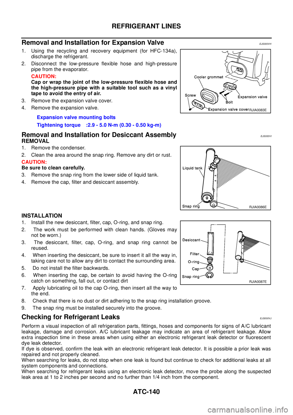
Removal and Installation for Expansion Valve
EJS000VH
1. Using the recycling and recovery equipment (for HFC-134a),
discharge the refrigerant.
2. Disconnect the low-pressure flexible hose and high-pressure
pipe from the evaporator.
CAUTION:
Cap or wrap the joint of the low-pressure flexible hose and
the high-pressure pipe with a suitable tool such as a vinyl
tape to avoid the entry of air.
3. Remove the expansion valve cover.
4. Remove the expansion valve.
Removal and Installation for Desiccant AssemblyEJS000VI
REMOVAL
1. Remove the condenser.
2. Clean the area around the snap ring. Remove any dirt or rust.
CAUTION:
Be sure to clean carefully.
3. Remove the snap ring from the lower side of liquid tank.
4. Remove the cap, filter and desiccant assembly.
INSTALLATION
1. Install the new desiccant, filter, cap, O-ring, and snap ring.
2. The work must be performed with clean hands. (Gloves may
not be worn.)
3. The desiccant, filter, cap, O-ring, and snap ring cannot be
reused.
4. When inserting the desiccant, be sure to insert it all the way in,
taking care not to allow any dirt to contact the surrounding area.
5. Do not install the filter backwards.
6. When inserting the cap, be certain to avoid having the O-ring
catch on something, fall out, or contact dirt
7. Apply lubricating oil to the cap O-ring, then insert all the way to
the end.
8. Check that there is no dust or dirt adhering to the snap ring installation groove.
9. The snap ring must be installed securely into the groove.
Checking for Refrigerant LeaksEJS000VJ
Perform a visual inspection of all refrigeration parts, fittings, hoses and components for signs of A/C lubricant
leakage, damage and corrosion. A/C lubricant leakage may indicate an area of refrigerant leakage. Allow
extra inspection time in these areas when using either an electronic refrigerant leak detector or fluorescent
dye leak detector.
If dye is observed, confirm the leak with an electronic refrigerant leak detector. It is possible a prior leak was
repaired and not properly cleaned.
When searching for leaks, do not stop when one leak is found but continue to check for additional leaks at all
system components and connections.
When searching for refrigerant leaks using an electronic leak detector, move the probe along the suspected
leak area at 1 to 2 inches per second and no further than 1/4 inch from the component.Expansion valve mounting bolts
Tightening torque :2.9 - 5.0 N-m (0.30 - 0.50 kg-m)
RJIA0083E
RJIA0086E
RJIA0087E
Page 1149 of 3066
![NISSAN X-TRAIL 2003 Electronic Owners Manual BASIC SERVICE PROCEDURE
EC-35
[QR (WITH EURO-OBD)]
C
D
E
F
G
H
I
J
K
L
MA
EC
lTo avoid unnecessary force or tension to hose, use moderately long fuel hose for fuel pressure check.
lDo not use the fuel](/img/5/57402/w960_57402-1148.png "NISSAN X-TRAIL 2003 Electronic Owners Manual BASIC SERVICE PROCEDURE
EC-35
[QR (WITH EURO-OBD)]
C
D
E
F
G
H
I
J
K
L
MA
EC
lTo avoid unnecessary force or tension to hose, use moderately long fuel hose for fuel pressure check.
lDo not use the fuel")
BASIC SERVICE PROCEDURE
EC-35
[QR (WITH EURO-OBD)]
C
D
E
F
G
H
I
J
K
L
MA
EC
lTo avoid unnecessary force or tension to hose, use moderately long fuel hose for fuel pressure check.
lDo not use the fuel hose for checking fuel pressure with damage or cracks on it.
lUse Pressure Gauge to check fuel pressure.
3. Remove fuel hose. Refer toEM-17, "
INTAKE MANIFOLD".
lDo not twist or kink fuel hose because it is plastic hose.
lDo not remove fuel hose from quick connector.
lKeep the original fuel hose to be free from intrusion of dust or foreign substances with a suitable cover.
4. Install the fuel pressure gauge as shown in the figure.
lWipe off oil or dirt from hose insertion part using cloth moist-
ened with gasoline.
lApply proper amount of gasoline between top of the fuel tube
and No.1 spool.
lInsert fuel hose for fuel pressure check until it touches the
No.1 spool on fuel tube.
lUse NISSAN genuine hose clamp (part number: 16439
N4710 or 16439 40U00).
lWhen reconnecting fuel line, always use new clamps.
lWhen reconnecting fuel hose, check the original fuel hose for
damage and abnormality.
lUse a torque driver to tighten clamps.
lInstall hose clamp to the position within 1 - 2 mm (0.04 - 0.08
in).
lMake sure that clamp screw does not contact adjacent parts.
5. After connecting fuel hose for fuel pressure check, pull the hose
with a force of approximately 98 N (10 kg, 22 lb) to confirm fuel
tube does not come off.
6. Turn ignition switch "ON", and check for fuel leakage.
7. Start engine and check for fuel leakage.
8. Read the indication of fuel pressure gauge.
lDo not perform fuel pressure check with system operating. Fuel pressure gauge may indicate false
readings.
lDuring fuel pressure check, confirm for fuel leakage from fuel connection every 3 minutes.
9. If result is unsatisfactory, go to next step.
10. Check the following.
lFuel hoses and fuel tubes for clogging
lFuel filter for clogging
lFuel pump
lFuel pressure regulator for clogging
If OK, replace fuel pressure regulator.
If NG, repair or replace.Tightening torque: 1 - 1.5 N·m (0.1 - 0.15 kg-m,
9-13in-lb)
At idling:
Approximately 350 kPa (3.5 bar, 3.7 kg/cm
2,51psi)
PBIB0669E
PBIB0670E
Page 1185 of 3066
![NISSAN X-TRAIL 2003 Electronic Owners Manual TROUBLE DIAGNOSIS
EC-71
[QR (WITH EURO-OBD)]
C
D
E
F
G
H
I
J
K
L
MA
EC
Air Air duct
55555 5EM-15
Air cleanerEM-15
Air leakage from air duct
(Mass air flow sensor —electric
throttle control actuator)](/img/5/57402/w960_57402-1184.png "NISSAN X-TRAIL 2003 Electronic Owners Manual TROUBLE DIAGNOSIS
EC-71
[QR (WITH EURO-OBD)]
C
D
E
F
G
H
I
J
K
L
MA
EC
Air Air duct
55555 5EM-15
Air cleanerEM-15
Air leakage from air duct
(Mass air flow sensor —electric
throttle control actuator)")
TROUBLE DIAGNOSIS
EC-71
[QR (WITH EURO-OBD)]
C
D
E
F
G
H
I
J
K
L
MA
EC
Air Air duct
55555 5EM-15
Air cleanerEM-15
Air leakage from air duct
(Mass air flow sensor —electric
throttle control actuator)
5555EM-15
Electric throttle control actuatorEM-17
Air leakage from intake manifold/
Collector/GasketEM-17
Cranking Battery
111111 11SC-3
Alternator circuitSC-12
Starter c irc uit 3SC-21
Signal plate 6EM-64
PNP switch
4MT-13or
AT- 1 3 5
Engine Cylinder head
55555 55 5EM-52
Cylinder head gasket 4 3
Cylinder block
66666 66 64
EM-64
Piston
Piston ring
Connecting rod
Bearing
Crankshaft
Va l v e
mecha-
nismTiming chain
55555 55 5EM-43
CamshaftEM-33
Intake valve
3EM-52
Exhaust valve
Exhaust Exhaust manifold/Tube/Muffler/
Gasket
55555 55 5EM-22
,EX-
2Three way catalyst
Lubrica-
tionOil pan/Oil strainer/Oil pump/Oil
filter/Oil gallery/Oil cooler
55555 55 52EM-24
,LU-
9,LU-10,
LU-13
Oil level (Low)/Filthy oilLU-7
SYMPTOM
Reference
page
HARD/NO START/RESTART (EXCP. HA)
ENGINE STALL
HESITATION/SURGING/FLAT SPOT
SPARK KNOCK/DETONATION
LACK OF POWER/POOR ACCELERATION
HIGH IDLE/LOW IDLE
ROUGH IDLE/HUNTING
IDLING VIBRATION
SLOW/NO RETURN TO IDLE
OVERHEATS/WATER TEMPERATURE HIGH
EXCESSIVE FUEL CONSUMPTION
EXCESSIVE OIL CONSUMPTION
BATTERY DEAD (UNDER CHARGE)
Warranty symptom code AA AB AC AD AE AF AG AH AJ AK AL AM HA
Page 1514 of 3066
![NISSAN X-TRAIL 2003 Electronic Owners Manual EC-400
[QR (WITHOUT EURO-OBD)]
BASIC SERVICE PROCEDURE
3. Remove fuel hose. Refer toEM-17, "INTAKE MANIFOLD".
lDo not twist or kink fuel hose because it is plastic hose.
lDo not remove fuel hose from](/img/5/57402/w960_57402-1513.png "NISSAN X-TRAIL 2003 Electronic Owners Manual EC-400
[QR (WITHOUT EURO-OBD)]
BASIC SERVICE PROCEDURE
3. Remove fuel hose. Refer toEM-17, \"INTAKE MANIFOLD\".
lDo not twist or kink fuel hose because it is plastic hose.
lDo not remove fuel hose from")
EC-400
[QR (WITHOUT EURO-OBD)]
BASIC SERVICE PROCEDURE
3. Remove fuel hose. Refer toEM-17, "INTAKE MANIFOLD".
lDo not twist or kink fuel hose because it is plastic hose.
lDo not remove fuel hose from quick connector.
lKeep the original fuel hose to be free from intrusion of dust or foreign substances with a suitable cover.
4. Install the fuel pressure gauge as shown in the figure.
lWipe off oil or dirt from hose insertion part using cloth moist-
ened with gasoline.
lApply proper amount of gasoline between top of the fuel tube
and No.1 spool.
lInsert fuel hose for fuel pressure check until it touches the
No.1 spool on fuel tube.
lUse NISSAN genuine hose clamp (part number: 16439
N4710 or 16439 40U00).
lWhen reconnecting fuel line, always use new clamps.
lWhen reconnecting fuel hose, check the original fuel hose for
damage and abnormality.
lUse a torque driver to tighten clamps.
lInstall hose clamp to the position within 1 - 2 mm (0.04 - 0.08
in).
lMake sure that clamp screw does not contact adjacent parts.
5. After connecting fuel hose for fuel pressure check, pull the hose
with a force of approximately 98 N (10 kg, 22 lb) to confirm fuel
tube does not come off.
6. Turn ignition switch "ON", and check for fuel leakage.
7. Start engine and check for fuel leakage.
8. Read the indication of fuel pressure gauge.
lDo not perform fuel pressure check with system operating. Fuel pressure gauge may indicate false
readings.
lDuring fuel pressure check, confirm for fuel leakage from fuel connection every 3 minutes.
9. If result is unsatisfactory, go to next step.
10. Check the following.
lFuel hoses and fuel tubes for clogging
lFuel filter for clogging
lFuel pump
lFuel pressure regulator for clogging
If OK, replace fuel pressure regulator.
IfNG,repairorreplace.Tightening torque: 1 - 1.5 N·m (0.1 - 0.15 kg-m, 9 - 13
in-lb)
At idling: Approximately 350 kPa (3.5 bar, 3.7 kg/cm
2,51psi)
PBIB0669E
PBIB0670E
Page 1533 of 3066
![NISSAN X-TRAIL 2003 Electronic Owners Manual TROUBLE DIAGNOSIS
EC-419
[QR (WITHOUT EURO-OBD)]
C
D
E
F
G
H
I
J
K
L
MA
EC
Air Air duct
55555 5EM-15
Air cleanerEM-15
Air leakage from air duct
(Mass air flow sensor —electric
throttle control actua](/img/5/57402/w960_57402-1532.png "NISSAN X-TRAIL 2003 Electronic Owners Manual TROUBLE DIAGNOSIS
EC-419
[QR (WITHOUT EURO-OBD)]
C
D
E
F
G
H
I
J
K
L
MA
EC
Air Air duct
55555 5EM-15
Air cleanerEM-15
Air leakage from air duct
(Mass air flow sensor —electric
throttle control actua")
TROUBLE DIAGNOSIS
EC-419
[QR (WITHOUT EURO-OBD)]
C
D
E
F
G
H
I
J
K
L
MA
EC
Air Air duct
55555 5EM-15
Air cleanerEM-15
Air leakage from air duct
(Mass air flow sensor —electric
throttle control actuator)
5555EM-15
Electric throttle control actuatorEM-17
Air leakage from intake manifold/
Collector/GasketEM-17
Cranking Battery
111111 11SC-3
Alternator circuitSC-12
Starter c irc uit 3SC-21
Signal plate 6EM-64
PNP switch
4MT-13or
AT- 3 8 8
Engine Cylinder head
55555 55 5EM-52
Cylinder head gasket 4 3
Cylinder block
66666 66 64
EM-64
Piston
Piston ring
Connecting rod
Bearing
Crankshaft
Va l v e
mecha-
nismTiming chain
55555 55 5EM-43
CamshaftEM-33
Intake valve
3EM-52
Exhaust valve
Exhaust Exhaust manifold/Tube/Muffler/
Gasket
55555 55 5EM-22
,EX-
2Three way catalyst
Lubrica-
tionOil pan/Oil strainer/Oil pump/Oil
filter/Oil gallery/Oil cooler
55555 55 52EM-24
,LU-
9,LU-10,
LU-13
Oil level (Low)/Filthy oilLU-7
SYMPTOM
Reference
page
HARD/NO START/RESTART (EXCP. HA)
ENGINE STALL
HESITATION/SURGING/FLAT SPOT
SPARK KNOCK/DETONATION
LACK OF POWER/POOR ACCELERATION
HIGH IDLE/LOW IDLE
ROUGH IDLE/HUNTING
IDLING VIBRATION
SLOW/NO RETURN TO IDLE
OVERHEATS/WATER TEMPERATURE HIGH
EXCESSIVE FUEL CONSUMPTION
EXCESSIVE OIL CONSUMPTION
BATTERY DEAD (UNDER CHARGE)
Warranty symptom code AA AB AC AD AE AF AG AH AJ AK AL AM HA
Page 1994 of 3066
![NISSAN X-TRAIL 2003 Electronic Owners Manual EM-24
[QR20DE]
OIL PAN AND OIL STRAINER
OIL PAN AND OIL STRAINER
P F P : 1111 0
Removal and InstallationEBS009QV
REMOVAL
WAR NIN G:
To avoid the danger of being scalded, never drain the engine oil whe](/img/5/57402/w960_57402-1993.png "NISSAN X-TRAIL 2003 Electronic Owners Manual EM-24
[QR20DE]
OIL PAN AND OIL STRAINER
OIL PAN AND OIL STRAINER
P F P : 1111 0
Removal and InstallationEBS009QV
REMOVAL
WAR NIN G:
To avoid the danger of being scalded, never drain the engine oil whe")
EM-24
[QR20DE]
OIL PAN AND OIL STRAINER
OIL PAN AND OIL STRAINER
P F P : 1111 0
Removal and InstallationEBS009QV
REMOVAL
WAR NIN G:
To avoid the danger of being scalded, never drain the engine oil when the engine is hot.
1. Remove engine under cover both side.
2. Drain engine oil. Refer toLU-8, "
Changing Engine Oil".
3. Remove lower oil pan bolts, Loosen bolts in the reverse order of
that shown in the figure.
4. Insert Tool Seal cutter between lower and upper oil pan.
5. Remove lower oil pan.
KBIA0095E
1 Oil level gauge guide 2 Oil pan upper 3 Cylinder block
4Oilfilter 5Oilstrainer 6Drainplug
7 Oil pan lower 8 Rear plate cover
KBIA0096E
Page 2135 of 3066
![NISSAN X-TRAIL 2003 Electronic Owners Manual PRIMARY TIMING CHAIN
EM-165
[YD22DDTi]
C
D
E
F
G
H
I
J
K
L
MA
EM
REMOVAL
1. Remove coolant reservior tank.
2. Remove charge air cooler. Refer toEM-114, "
Removal and Installation".
3. Remove oil clean](/img/5/57402/w960_57402-2134.png "NISSAN X-TRAIL 2003 Electronic Owners Manual PRIMARY TIMING CHAIN
EM-165
[YD22DDTi]
C
D
E
F
G
H
I
J
K
L
MA
EM
REMOVAL
1. Remove coolant reservior tank.
2. Remove charge air cooler. Refer toEM-114, \"
Removal and Installation\".
3. Remove oil clean")
PRIMARY TIMING CHAIN
EM-165
[YD22DDTi]
C
D
E
F
G
H
I
J
K
L
MA
EM
REMOVAL
1. Remove coolant reservior tank.
2. Remove charge air cooler. Refer toEM-114, "
Removal and Installation".
3. Remove oil cleaner and air duct. Refer toEM-112, "
Removal and Installation".
4. Remove rocker cover. Refer toEM-147, "
Removal and Installation".
5. Remove RH engine mount insulator and bracket. Refer toEM-184, "
Removal and Installation".
6. Pull power steering reservoir tank out of brackets to move power steering piping.
CAUTION:
To avoid removing power steering reservoir tank out of brackets move it with power steering pip-
ing aside.
7. Remove oil pan. Refer toEM-125, "
Removal and Installation".
8. Remove oil filter bracket. Refer toLU-22, "
Removal and Installation".
9. Remove injection tube and fuel injector. Refer toEM-135, "
Removal and Installation".
10. Remove secondary timing chain and associated parts. Refer toEM-158, "
Removal and Installation".
11. When removing rear chain case, remove camshaft sprockets. Refer toEM-149, "
Removal and Installa-
tion".
12. Remove crankshaft pulley.
a. Hold crankshaft pulley with the pulley holder (SST).
b. Loosen crankshaft pulley fixing bolt and pull out the bolt approx-
imately 10 mm (0.39 in).
c. Using pulley puller (SST), remove crankshaft pulley.
lUse two M6 bolts with approx. 60 mm (2.36 in) shank length
for securing crankshaft pulley.
7. Chain guide 8. Spacer 9. Front chain case
10. Crankshaft pully 11. Front oil seal 12. Oil pump
13. Primary timing chain 14. Oil pump drive sprocket 15. Crankshaft sprocket
16. Secondary timing chain 17. Rear chain case 18. Power steering pump
JEM131G
JEM132G
Page 2223 of 3066
![NISSAN X-TRAIL 2003 Electronic Owners Manual FL-8
[QR20DE]
FUEL LEVEL SENSOR UNIT, FUEL FILTER AND FUEL PUMP ASSEMBLY
2. Disconnect fuel pump harness connector.
3. Separate the fuel filter and fuel level sensor unit.
a. Fit a used O-ring into sp](/img/5/57402/w960_57402-2222.png "NISSAN X-TRAIL 2003 Electronic Owners Manual FL-8
[QR20DE]
FUEL LEVEL SENSOR UNIT, FUEL FILTER AND FUEL PUMP ASSEMBLY
2. Disconnect fuel pump harness connector.
3. Separate the fuel filter and fuel level sensor unit.
a. Fit a used O-ring into sp")
FL-8
[QR20DE]
FUEL LEVEL SENSOR UNIT, FUEL FILTER AND FUEL PUMP ASSEMBLY
2. Disconnect fuel pump harness connector.
3. Separate the fuel filter and fuel level sensor unit.
a. Fit a used O-ring into space between fuel level sensor unit and
fuel filter. Undo catches and separate fuel level sensor unit and
fuel filter.
lFor reference when reassembling, put a mating mark on outer
edges of fuel level sensor unit and fuel filter with some means
which cannot be erased by fuel.
b. Insert blade end screwdriver to the gap between the fuel filter
and fuel level sensor unit to separate them.
CAUTION:
Put cloth or similar one on the edge of screwdriver not to
damage the inserted portion.
4. Remove pressure regulator from fuel filter.
a. Open and remove the clip.
b. Pull the pressure regulator straight out during removal.
CAUTION:
lAvoid impacts such as falling during removal.
lDo not disassemble or adjust.
ASSEMBLY
Install in the reverse order of removal paying attention to the following.
lInstall the fuel filter and fuel pump with the tabs aligned, Make sure a click sound of secure engagement
is heard.
lSecurely connect the harness connector of the fuel pump.
lInstall the pressure regulator O-ring as follows.
CAUTION:
lWhen replacing, always use a new O-ring.
lHandle it with bare hands. (Do not use gloves.)
lVisually check the O-ring, mounting parts and mating parts for foreign materials and flaws.
lBefore installing, apply new engine oil.
lTo avid damage, do not apply an excessive force (pulling or starching).
lInstall the pressure regulator as follows.
1. Insert the clip to the groove of the regulator.
2. With the clip installed, insert the regulator straight by matching
the fuel filter protrusion and the clip notch.
3. Make sure that the fuel filter protrusion and clip notch are
securely engaged.
PBIC0243E
PBIC0244E
PBIC0245E
Page 2260 of 3066
PRECAUTIONS
GI-7
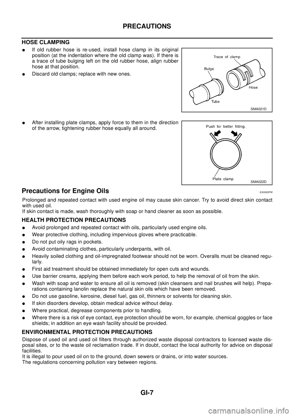
HOSE CLAMPING
lIf old rubber hose is re-used, install hose clamp in its original
position (at the indentation where the old clamp was). If there is
a trace of tube bulging left on the old rubber hose, align rubber
hose at that position.
lDiscard old clamps; replace with new ones.
lAfter installing plate clamps, apply force to them in the direction
of the arrow, tightening rubber hose equally all around.
Precautions for Engine OilsEAS000FW
Prolonged and repeated contact with used engine oil may cause skin cancer. Try to avoid direct skin contact
with used oil.
If skin contact is made, wash thoroughly with soap or hand cleaner as soon as possible.
HEALTH PROTECTION PRECAUTIONS
lAvoid prolonged and repeated contact with oils, particularly used engine oils.
lWear protective clothing, including impervious gloves where practicable.
lDo not put oily rags in pockets.
lAvoid contaminating clothes, particularly underpants, with oil.
lHeavily soiled clothing and oil-impregnated footwear should not be worn. Overalls must be cleaned regu-
larly.
lFirst aid treatment should be obtained immediately for open cuts and wounds.
lUse barrier creams, applying them before each work period, to help the removal of oil from the skin.
lWash with soap and water to ensure all oil is removed (skin cleansers and nail brushes will help). Prepa-
rations containing lanolin replace the natural skin oils which have been removed.
lDo not use gasoline, kerosine, diesel fuel, gas oil, thinners or solvents for cleaning skin.
lIf skin disorders develop, obtain medical advice without delay.
lWhere practical, degrease components prior to handling.
lWhere there is a risk of eye contact, eye protection should be worn, for example, chemical goggles or face
shields; in addition an eye wash facility should be provided.
ENVIRONMENTAL PROTECTION PRECAUTIONS
Dispose of used oil and used oil filters through authorized waste disposal contractors to licensed waste dis-
posal sites, or to the waste oil reclamation trade. If in doubt, contact the local authority for advice on disposal
facilities.
It is illegal to pour used oil on to the ground, down sewers or drains, or into water sources.
The regulations concerning pollution vary between regions.
SMA021D
SMA022D
Page 2359 of 3066
IDX-2
ALPHABETICAL INDEX
Numerics
4WD mode switch ...................................TF-53
,TF-57
4WD shift indicator lamp .........................TF-32,TF-54
4WD solenoid valve ................................TF-49,TF-51
4WD warning lamp ..........TF-32,TF-40,TF-55,TF-58
A
A/C air flow .........................................ATC-28
,MTC-5
A/C component layout .....................................ATC-20
A/C compressor clutch removal and installation ...........
ATC-129
A/C compressor precaution ...............................ATC-7
A/C compressor special service tool ................ATC-11
A/C diagnostic work flow (auto A/C) ................ATC-30
A/C HFC134a (R134a) system precaution ........ATC-4
A/C HFC134a (R134a) system service procedure .......
ATC-123
A/C HFC134a (R134a) system service tools ...ATC-12
A/C HFC134a system service equipment precaution ...
ATC-8
A/C lubricant (R134a) ......................................ATC-21
A/C operational check .........................ATC-51,MTC-7
A/C performance test diagnoses .....................ATC-83
A/C reray ..........................................................ATC-80
A/C self-diagnoses (auto A/C) .........................ATC-42
A/C service data specification ........................ATC-143
A/C system description (auto A/C) ...................ATC-24
A/C trouble diagnoses (auto A/C) .......ATC-30,MTC-3
A/C, A - Wiring diagram ...................................ATC-35
A/CCUT - Wiring diagram ................................EC-824
A/T - Wiring diagram - AT - FTS ......................AT-138
A/T - Wiring diagram - AT - MAIN ....................AT-389
A/T - Wiring diagram - AT - PNP/SW ...............AT-132
A/T - Wiring diagram - AT - VSS A/T .AT-144,AT-394
A/T fluid checking ..................................AT-13,MA-36
A/T fluid replacement .............................AT-13,MA-36
A/T fluid temperature sensor ...........................AT-141
A/T IND - Wiring diagram ....................................DI-51
A/T indicator ........................................................DI-51
A/T shift lock system ........................................AT-446
A/T shift lock system - Wiring diagram ............AT-447
A/T trouble diagnoses ..........................AT-56,AT-279
A/T Wiring diagram - AT - ENG SS ...AT-148,AT-433
A/T Wiring diagram AT - 1ST ...........................AT-154
A/T Wiring diagram AT - 2ND ..........................AT-161
A/T Wiring diagram AT - 3RD ..........................AT-168
A/T Wiring diagram AT - 4TH ..........................AT-175
A/T Wiring diagram AT - BA/FTS .......AT-218,AT-428
A/T Wiring diagram AT - LPSV ..........AT-188,AT-438
A/T Wiring diagram AT - OVRCSV ....AT-210,AT-418
A/T Wiring diagram AT - SSV/A .........AT-195,AT-408
A/T Wiring diagram AT - SSV/B .........AT-200,AT-413
A/T Wiring diagram AT - TCV ............AT-183,AT-423
A/T Wiring diagram AT - TPS ............AT-205,AT-403
A/T Wiring diagrawm AT - VSSMTR ..AT-224,AT-399
ABS - Wiring diagram .....................................BRC-12
Absolute pressure sensor ................................EC-749
Accelerator control system ...............................ACC-2
Accelerator pedal position (APP) sensor ........EC-154,
EC-484
,EC-715
Accelerator pedal released position learning ...EC-664
Accelerator pedal released position switch ......EC-783
Actuator relay .....................................................TF-51
Aiming adjustment ...............................................LT-4
Air bag ..............................................................SRS-3
Air bag disposal ..............................................SRS-40
Air bleeding (hydraulic clutch) ..............................CL-8
Air bleeding for brake system ............................BR-10
Air cleaner and air duct(QR20DE) ....................EM-15
Air cleaner and air duct(YD22DDTi) ...............EM-112
Air cleaner filter replacement(QR20DE) ...........MA-23
Air cleaner filter replacement(YD22DDTi) .........MA-31
Air cleaner filter(QR20DE) ................................EM-15
Air cleaner filter(YD22DDTi) ...........................EM-112
Air conditioner cut control .....EC-27,EC-392,EC-662
Air flow meter - See Mass air flow sensor .......EC-130,
EC-260
,EC-463
Air mix door control linkage adjustment .........ATC-64,
ATC-119
,MTC-9,MTC-28
Air mix. door motor .........................ATC-61,ATC-119
Air spoiler, rear ...................................................EI-21
Alternator ...........................................................SC-12
Ambient sensor .................ATC-93,ATC-95,ATC-105
Angular tightening application(QR20DE) ............EM-5
Angular tightening application(YD22DDTi) .....EM-102
Antenna - See Power antenna ...........................AV-15
APPS - Wiring diagram .......EC-156,EC-486,EC-717
APRSW - Wiring diagram ................................EC-785
Audio ....................................................................AV-3
Auto air conditioner - Wiring diagram .............ATC-35
Automatic amplifier ...........................ATC-41,ATC-53
Automatic transmission fluid replacement .......MA-35,
MA-37
Axle ...................................................................MA-41
B
Back door ...........................................................BL-60
Back door trim .....................................................EI-25
Back door window ..............................................GW-7
Back window ......................................................GW-7
BACK/L - Wiring diagram ...................................LT-28
Back-up lamp ..........................................LT-28,LT-42
Back-up lamp switch (M/T) ...............................MT-13
Basic inspection ....................EC-64,EC-412,EC-672
Battery .................................................................SC-3
Baulk ring (M/T) ....................................MT-19,MT-24
Blower motor .....ATC-67,ATC-73,ATC-111,MTC-13,
MTC-17
,MTC-20
Blower resistor ................................................MTC-21
Blower unit .....................................ATC-109,MTC-20
Brake booster ....................................................BR-17
Brake fluid change ...............................................BR-9
Brake fluid level ................................................MA-38