horn NISSAN X-TRAIL 2003 Electronic Repair Manual
[x] Cancel search | Manufacturer: NISSAN, Model Year: 2003, Model line: X-TRAIL, Model: NISSAN X-TRAIL 2003Pages: 3066, PDF Size: 51.47 MB
Page 1 of 3066
MODEL T30 SERIES
2001 NISSAN EUROPE N.V.
All rights reserved. No part of this Electronic Service Manual may be reproduced or stored in a retrieval system, or transmitted in any
form, or by any means, electronic, mechanical, photocopying, recording or otherwise, without the prior written permission of Nissan
Europe N.V., Paris, France.
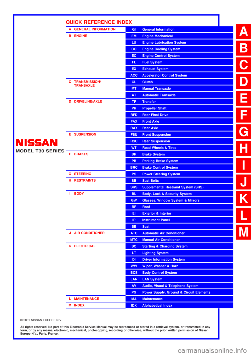
A GENERAL INFORMATION
B ENGINE
C TRANSMISSION/
TRANSAXLE
D DRIVELINE/AXLE
E SUSPENSION
F BRAKES
G STEERING
H RESTRAINTS
I BODY
J AIR CONDITIONER
K ELECTRICAL
L MAINTENANCE
M INDEXGI General Information
EM Engine Mechanical
LU Engine Lubrication System
CO Engine Cooling System
EC Engine Control System
FL Fuel System
EX Exhaust System
ACC Accelerator Control System
CL Clutch
MT Manual Transaxle
AT Automatic Transaxle
TF Transfer
PR Propeller Shaft
RFD Rear Final Drive
FAX Front Axle
RAX Rear Axle
FSU Front Suspension
RSU Rear Suspension
WT Road Wheels & Tires
BR Brake System
PB Parking Brake System
BRC Brake Control System
PS Power Steering System
SB Seat Belts
SRS Supplemental Restraint System (SRS)
BL Body, Lock & Security System
GW Glasses, Window System & Mirrors
RF Roof
EI Exterior & Interior
IP Instrument Panel
SE Seat
ATC Automatic Air Conditioner
MTC Manual AIr Conditioner
SC Starting & Charging System
LT Lighting System
DI Driver Information System
WW Wiper, Washer & Horn
BCS Body Control System
LAN LAN System
AV Audio, Visual & Telephone System
PG Power Supply, Ground & Circuit Elements
MA Maintenance
IDX Alphabetical Index
QUICK REFERENCE INDEX
A
B
C
D
E
F
G
H
I
J
K
L
M
Page 1024 of 3066
![NISSAN X-TRAIL 2003 Electronic Repair Manual CO-14
[QR20DE]
RADIATOR
lCheck radiator cap relief pressure.
lWhen connecting the radiator cap to the tester, apply water or
LLC to the cap seal part.
lReplace the radiator cap if there is an unusualn NISSAN X-TRAIL 2003 Electronic Repair Manual CO-14
[QR20DE]
RADIATOR
lCheck radiator cap relief pressure.
lWhen connecting the radiator cap to the tester, apply water or
LLC to the cap seal part.
lReplace the radiator cap if there is an unusualn](/img/5/57402/w960_57402-1023.png)
CO-14
[QR20DE]
RADIATOR
lCheck radiator cap relief pressure.
lWhen connecting the radiator cap to the tester, apply water or
LLC to the cap seal part.
lReplace the radiator cap if there is an unusualness in the nega-
tive-pressure valve, or if the open-valve pressure is outside of
the standard values.
CHECKING RADIATOR
Check radiator for mud or clogging. If necessary, clean radiator as follows.
lBe careful not to bend or damage the radiator fins.
lWhen radiator is cleaned without removal, remove all surrounding parts such as cooling fan, radiator
shroud and horns. Then tape the harness and connectors to prevent water from entering.
1. Apply water by hose to the back side of the radiator core vertically downwards.
2. Apply water again to all radiator core surface once per minute.
3. Stop washing if any stains no longer flow out from the radiator.
4. Blow air into the back side of radiator core vertically downwards.
lUsecompressedairlowerthan490kPa(5kg/cm2, 71psi) and keep distance more than 30 cm(11.8 in).
5. Blow air again into all the radiator core surface once per minute until no water sprays out.Standard
: 78- 98 kPa (0.78-0.98bar, 0.8 - 1.0 kg/cm
2,
11 - 14 psi)
Limit
: 59kpa (0.59bar, 0.6kg/cm
2,9psi)
SLC135B
Page 1045 of 3066
![NISSAN X-TRAIL 2003 Electronic Repair Manual RADIATOR
CO-35
[YD22DDTi]
C
D
E
F
G
H
I
J
K
L
MA
CO
lCheck radiator cap relief pressure.
lWhen connecting the radiator cap to the tester, apply water or
LLC to the cap seal part.
lReplace the radiator NISSAN X-TRAIL 2003 Electronic Repair Manual RADIATOR
CO-35
[YD22DDTi]
C
D
E
F
G
H
I
J
K
L
MA
CO
lCheck radiator cap relief pressure.
lWhen connecting the radiator cap to the tester, apply water or
LLC to the cap seal part.
lReplace the radiator](/img/5/57402/w960_57402-1044.png)
RADIATOR
CO-35
[YD22DDTi]
C
D
E
F
G
H
I
J
K
L
MA
CO
lCheck radiator cap relief pressure.
lWhen connecting the radiator cap to the tester, apply water or
LLC to the cap seal part.
lReplace the radiator cap if there is an unusualness in the nega-
tive-pressure valve, or if the open-valve pressure is outside of
the standard values.
Checking RadiatorEBS00BRH
Check radiator for mud or clogging. If necessary, clean radiator as follows.
lBe careful not to bend or damage the radiator fins.
lWhen radiator is cleaned without removal, remove all surrounding parts such as cooling fan, radiator
shroud and horns. Then tape the harness and connectors to prevent water from entering.
1. Apply water by hose to the back side of the radiator core vertically downwards.
2. Apply water again to all radiator core surface once per minute.
3. Stop washing if any stains no longer flow out from the radiator.
4. Blow air into the back side of radiator core vertically downwards.
lUse compressed air lower than 490 kpa (4.9bar 5 kg/cm2, 71psi) and keep distance more than 30
cm(11.8 in).
5. Blow air again into all the radiator core surface once per minute until no water sprays out.Standard
: 78 - 98 kpa (0.78 - 0.98bar, 0.8 - 1.0 kg/cm
2
,11-14psi)
Limit : 59kpa (0.59 bar, 0.6 kg/cm
2,9psi)
SLC135B
Page 2174 of 3066
![NISSAN X-TRAIL 2003 Electronic Repair Manual EM-204
[YD22DDTi]
CYLINDER BLOCK
MAIN BEARING HOUSING INNER DIAMETER
lWithout installing main bearings, install main bearing caps, and
tighten bolts to the specified torque.
lMeasure the inner diamete NISSAN X-TRAIL 2003 Electronic Repair Manual EM-204
[YD22DDTi]
CYLINDER BLOCK
MAIN BEARING HOUSING INNER DIAMETER
lWithout installing main bearings, install main bearing caps, and
tighten bolts to the specified torque.
lMeasure the inner diamete](/img/5/57402/w960_57402-2173.png)
EM-204
[YD22DDTi]
CYLINDER BLOCK
MAIN BEARING HOUSING INNER DIAMETER
lWithout installing main bearings, install main bearing caps, and
tighten bolts to the specified torque.
lMeasure the inner diameter of main bearing housing with a bore
gauge.
lIf the measurement is out of the specified range, replace cylin-
der block and main bearing caps.
PISTON TO CYLINDER BORE CLEARANCE
Cylinder Bore Inner Diameter
lUsing bore gauge, measure cylinder inner diameters at 6 posi-
tions; top, middle, and bottom (A, B, C) in 2 directions (X, Y).
lIf clearance exceeds the limit, or any flaws or seizures are found
on inner surface of cylinder, horn or bore the applicable cylinder
or redore all cylinder.
Piston Outer Diameter
Use micrometer to measure piston skirt outer diameter.
Calculation of Piston to Piston Bore Clearance
lCalculate using piston skirt outer diameter and cylinder inner diameter (direction X, position B).
(Clearance) = (Cylinder inner diameter)-(Piston skirt outer diameter) Standard : 66.654 - 66.681 mm (2.6242 - 2.6252 in) dia.
JEM214G
Cylinder inner diameter:
Standard : 86.000 - 86.030 mm
(3.3858 - 3.5870 in) dia.
Wear limit : 0.07 mm (0.0028 in)
Out-of-round limit (X - Y) : 0.015 mm (0.0006 in)
Taper limit (A - B - C) : 0.010 mm (0.0004 in)
JEM207G
FEM110
Piston skirt diameter:
Measurement position : 48.83 mm (1.9224 in)
Distance from the top
Standard : 85.925 - 85.955 mm
(3.3829 - 3.3841 in) dia.
0.25 (0.0098) O/S : 86.175 - 86.205 )
(3.3927 - 3.3939
0.50 (0.0197) O/S : 86.425 - 86.455
(3.4026 - 3.4036)
Specifications at room temperature [20°C(68°F)]:
0.065 - 0.085 mm (0.0026 - 0.0033 in)
PBIC0125E
Page 2362 of 3066
IDX-5
A
C
D
E
F
G
H
I
J
K
L B
IDX
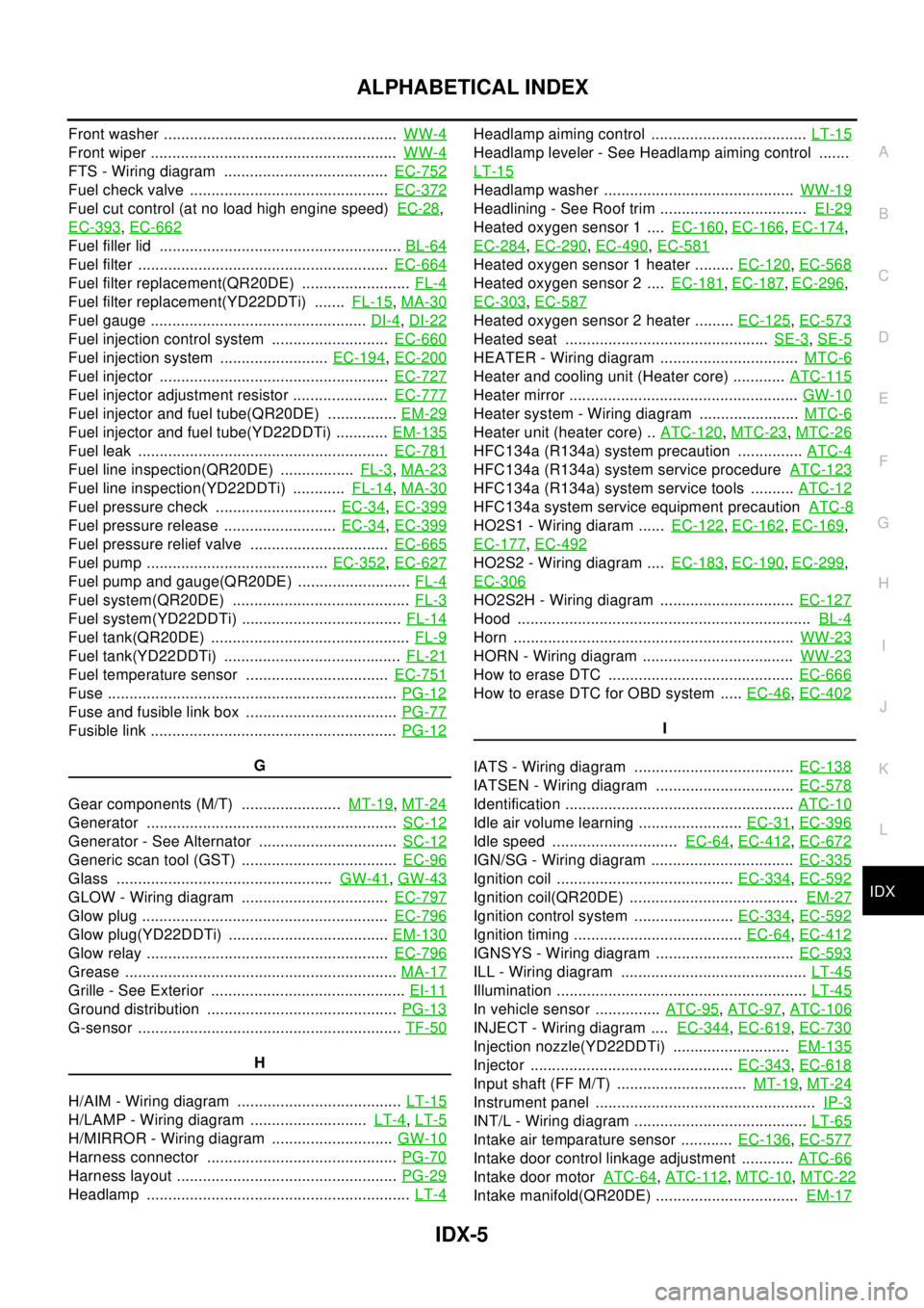
ALPHABETICAL INDEX
Front washer ......................................................WW-4
Front wiper .........................................................WW-4
FTS - Wiring diagram ......................................EC-752
Fuel check valve ..............................................EC-372
Fuel cut control (at no load high engine speed)EC-28,
EC-393
,EC-662
Fuel filler lid ........................................................BL-64
Fuel filter ..........................................................EC-664
Fuel filter replacement(QR20DE) .........................FL-4
Fuel filter replacement(YD22DDTi) .......FL-15,MA-30
Fuel gauge ..................................................DI-4,DI-22
Fuel injection control system ...........................EC-660
Fuel injection system .........................EC-194,EC-200
Fuel injector .....................................................EC-727
Fuel injector adjustment resistor ......................EC-777
Fuel injector and fuel tube(QR20DE) ................EM-29
Fuel injector and fuel tube(YD22DDTi) ............EM-135
Fuel leak ..........................................................EC-781
Fuel line inspection(QR20DE) .................FL-3,MA-23
Fuel line inspection(YD22DDTi) ............FL-14,MA-30
Fuel pressure check ............................EC-34,EC-399
Fuel pressure release ..........................EC-34,EC-399
Fuel pressure relief valve ................................EC-665
Fuel pump ..........................................EC-352,EC-627
Fuel pump and gauge(QR20DE) ..........................FL-4
Fuel system(QR20DE) .........................................FL-3
Fuel system(YD22DDTi) .....................................FL-14
Fuel tank(QR20DE) ..............................................FL-9
Fuel tank(YD22DDTi) .........................................FL-21
Fuel temperature sensor .................................EC-751
Fuse ...................................................................PG-12
Fuse and fusible link box ...................................PG-77
Fusible link .........................................................PG-12
G
Gear components (M/T) .......................MT-19
,MT-24
Generator ..........................................................SC-12
Generator - See Alternator ................................SC-12
Generic scan tool (GST) ....................................EC-96
Glass ..................................................GW-41,GW-43
GLOW - Wiring diagram ..................................EC-797
Glow plug .........................................................EC-796
Glow plug(YD22DDTi) .....................................EM-130
Glow relay ........................................................EC-796
Grease ...............................................................MA-17
Grille - See Exterior .............................................EI-11
Ground distribution ............................................PG-13
G-sensor .............................................................TF-50
H
H/AIM - Wiring diagram ......................................LT-15
H/LAMP - Wiring diagram ...........................LT-4,LT-5
H/MIRROR - Wiring diagram ............................GW-10
Harness connector ............................................PG-70
Harness layout ...................................................PG-29
Headlamp .............................................................LT-4
Headlamp aiming control ....................................LT-15
Headlamp leveler - See Headlamp aiming control .......
LT-15
Headlamp washer ............................................WW-19
Headlining - See Roof trim ..................................EI-29
Heated oxygen sensor 1 ....EC-160,EC-166,EC-174,
EC-284
,EC-290,EC-490,EC-581
Heated oxygen sensor 1 heater .........EC-120,EC-568
Heated oxygen sensor 2 ....EC-181,EC-187,EC-296,
EC-303
,EC-587
Heated oxygen sensor 2 heater .........EC-125,EC-573
Heated seat ...............................................SE-3,SE-5
HEATER - Wiring diagram ................................MTC-6
Heater and cooling unit (Heater core) ............ATC-115
Heater mirror .....................................................GW-10
Heater system - Wiring diagram .......................MTC-6
Heater unit (heater core) ..ATC-120,MTC-23,MTC-26
HFC134a (R134a) system precaution ...............ATC-4
HFC134a (R134a) system service procedureATC-123
HFC134a (R134a) system service tools ..........ATC-12
HFC134a system service equipment precautionATC-8
HO2S1 - Wiring diaram ......EC-122,EC-162,EC-169,
EC-177
,EC-492
HO2S2 - Wiring diagram ....EC-183,EC-190,EC-299,
EC-306
HO2S2H - Wiring diagram ...............................EC-127
Hood ....................................................................BL-4
Horn .................................................................WW-23
HORN - Wiring diagram ...................................WW-23
How to erase DTC ...........................................EC-666
HowtoeraseDTCforOBDsystem .....EC-46,EC-402
I
IATS - Wiring diagram .....................................EC-138
IATSEN - Wiring diagram ................................EC-578
Identification .....................................................ATC-10
Idle air volume learning ........................EC-31,EC-396
Idle speed .............................EC-64,EC-412,EC-672
IGN/SG - Wiring diagram .................................EC-335
Ignition coil .........................................EC-334,EC-592
Ignition coil(QR20DE) .......................................EM-27
Ignition control system .......................EC-334,EC-592
Ignition timing .......................................EC-64,EC-412
IGNSYS - Wiring diagram ................................EC-593
ILL - Wiring diagram ...........................................LT-45
Illumination ..........................................................LT-45
In vehicle sensor ...............ATC-95,ATC-97,ATC-106
INJECT - Wiring diagram ....EC-344,EC-619,EC-730
Injection nozzle(YD22DDTi) ...........................EM-135
Injector ...............................................EC-343,EC-618
Input shaft (FF M/T) ..............................MT-19,MT-24
Instrument panel ...................................................IP-3
INT/L - Wiring diagram ........................................LT-65
Intake air temparature sensor ............EC-136,EC-577
Intake door control linkage adjustment ............ATC-66
Intake door motorATC-64,ATC-112,MTC-10,MTC-22
Intake manifold(QR20DE) .................................EM-17
Page 2442 of 3066
LT-44
COMBINATION SWITCH
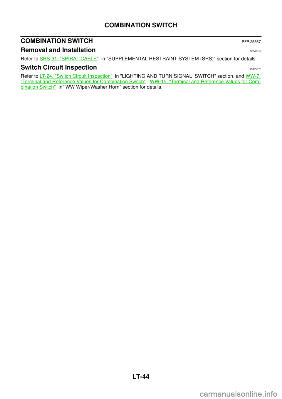
COMBINATION SWITCH
PFP:25567
Removal and InstallationEKS001V6
Refer toSRS-31, "SPIRAL CABLE"in "SUPPLEMENTAL RESTRAINT SYSTEM (SRS)" section for details.
Switch Circuit InspectionEKS001V7
Refer toLT- 2 4 , "Switch Circuit Inspection"in "LIGHTING AND TURN SIGNAL SWITCH" section, andWW-7,
"Terminal and Reference Values for Combination Switch",WW-15, "Terminal and Reference Values for Com-
bination Switch"in“ WW Wiper/Washer Horn” section for details.
Page 2496 of 3066
MA-4
DESCRIPTION
DESCRIPTION
PFP:00000
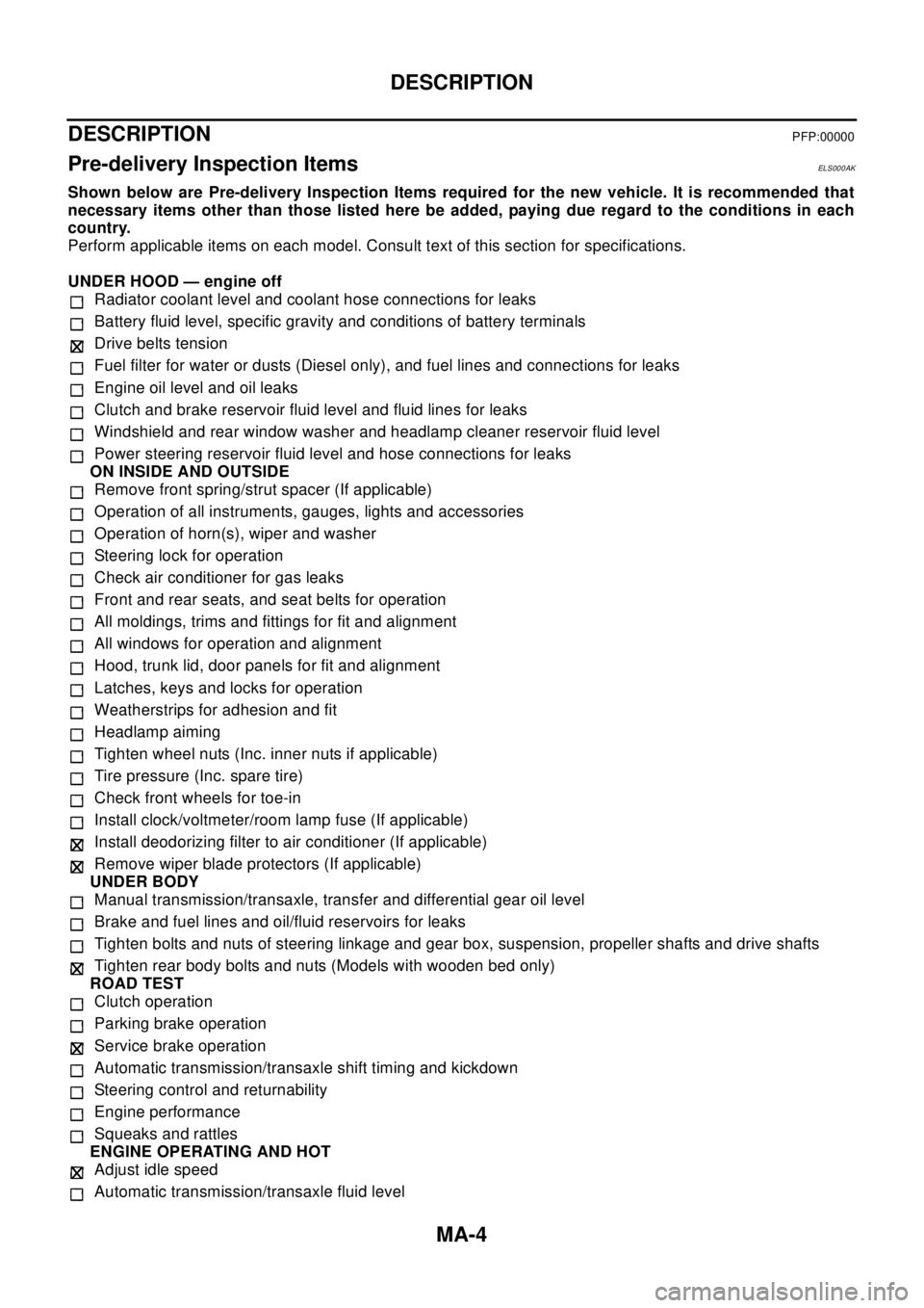
Pre-delivery Inspection ItemsELS000AK
Shown below are Pre-delivery Inspection Items required for the new vehicle. It is recommended that
necessary items other than those listed here be added, paying due regard to the conditions in each
country.
Perform applicable items on each model. Consult text of this section for specifications.
UNDER HOOD — engine off
Radiator coolant level and coolant hose connections for leaks
Battery fluid level, specific gravity and conditions of battery terminals
Drive belts tension
Fuel filter for water or dusts (Diesel only), and fuel lines and connections for leaks
Engine oil level and oil leaks
Clutch and brake reservoir fluid level and fluid lines for leaks
Windshield and rear window washer and headlamp cleaner reservoir fluid level
Power steering reservoir fluid level and hose connections for leaks
ON INSIDE AND OUTSIDE
Remove front spring/strut spacer (If applicable)
Operation of all instruments, gauges, lights and accessories
Operation of horn(s), wiper and washer
Steering lock for operation
Check air conditioner for gas leaks
Front and rear seats, and seat belts for operation
All moldings, trims and fittings for fit and alignment
All windows for operation and alignment
Hood, trunk lid, door panels for fit and alignment
Latches, keys and locks for operation
Weatherstrips for adhesion and fit
Headlamp aiming
Tighten wheel nuts (Inc. inner nuts if applicable)
Tire pressure (Inc. spare tire)
Check front wheels for toe-in
Install clock/voltmeter/room lamp fuse (If applicable)
Install deodorizing filter to air conditioner (If applicable)
Remove wiper blade protectors (If applicable)
UNDER BODY
Manual transmission/transaxle, transfer and differential gear oil level
Brake and fuel lines and oil/fluid reservoirs for leaks
Tighten bolts and nuts of steering linkage and gear box, suspension, propeller shafts and drive shafts
Tighten rear body bolts and nuts (Models with wooden bed only)
ROAD TEST
Clutch operation
Parking brake operation
Service brake operation
Automatic transmission/transaxle shift timing and kickdown
Steering control and returnability
Engine performance
Squeaks and rattles
ENGINE OPERATING AND HOT
Adjust idle speed
Automatic transmission/transaxle fluid level
Page 2514 of 3066
MA-22
ENGINE MAINTENANCE (QR20DE)
2. Run engine and warm it up to normal operating temperature.
3. Rev engine two or three times under no-load.
4. Stop engine and wait until it cools down.
5. Drain water.
6. Repeat steps 1 through 5 until clear water begins to drain from radiator.
Checking Cooling SystemELS000C1
WAR NIN G:
Never remove the radiator cap when the engine is hot; serious burns could be caused by high pres-
sure fluid escaping from the radiator.
Wrap a thick cloth around the cap and carefully remove it by turning it a quarter turn to allow built-up
pressure to escape and then turn the cap all the way off.
CHECKING COOLING SYSTEM HOSES
Check hoses for improper attachment, leaks, cracks, damage, loose connections, chafing and deterioration.
CHECKING RADIATOR
Check radiator for mud or clogging. If necessary, clean radiator as follows.
lBe careful not to bend or damage the radiator fins.
lWhen radiator is cleaned without removal, remove all surrounding parts such as cooling fan, radiator
shroud and horns. Then tape the harness and connectors to prevent water from entering.
1. Apply water by hose to the back side of the radiator core vertically downward.
2. Apply water again to all radiator core surfaces once per minute.
3. Stop washing if any stains no longer flow out from the radiator.
4. Blow air into the back side of radiator core vertically downward.
lUsecompressedairlowerthan490kPa(5kg/cm2, 71 psi) and keep distance more than 30 cm (11.8
in).
5. Blow air again into all the radiator core surfaces once per minute until no water sprays out.
CHECKING RADIATOR CAP
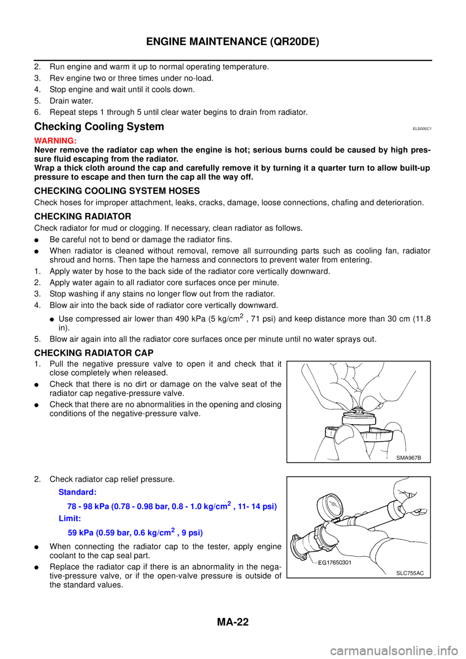
1. Pull the negative pressure valve to open it and check that it
close completely when released.
lCheck that there is no dirt or damage on the valve seat of the
radiator cap negative-pressure valve.
lCheck that there are no abnormalities in the opening and closing
conditions of the negative-pressure valve.
2. Check radiator cap relief pressure.
lWhen connecting the radiator cap to the tester, apply engine
coolant to the cap seal part.
lReplace the radiator cap if there is an abnormality in the nega-
tive-pressure valve, or if the open-valve pressure is outside of
the standard values.
SMA967B
Standard:
78-98kPa(0.78-0.98bar,0.8-1.0kg/cm
2, 11- 14 psi)
Limit:
59 kPa (0.59 bar, 0.6 kg/cm
2,9psi)
SLC755AC
Page 2521 of 3066
ENGINE MAINTENANCE (YD22DDTI)
MA-29
C
D
E
F
G
H
I
J
K
MA
B
MA
10. Warm up engine, and check for sound of coolant flow while running engine from idle up to 3,000 rpm with
heater temperature controller set at several position between COOL and WARM.
lSound may be noticeable at heater unit.
11. If sound is heard, bleed air from cooling system by repeating steps 5 through 7 until coolant level no
longer drops.
lClean excess coolant from engine.
FLUSHING COOLING SYSTEM
1. Fill radiator with water until water spills from the air relief hole, then close air relief flag. Fill radiator and
reservoir tank with water and reinstall radiator cap.
2. Run engine and warm it up to normal operating temperature.
3. Rev engine two or three times under no-load.
4. Stop engine and wait until it cools down.
5. Drain water.
6. Repeat steps 1 through 5 until clear water begins to drain from radiator.
Checking Cooling SystemELS000C4
WA RN ING:
Never remove the radiator cap when the engine is hot. Serious burns could occur from high pressure
coolant escaping from the radiator. Wrap a thick cloth around the cap. Slowly turn it a quarter turn to
allow built-up pressure to escape. Carefully remove the cap by turning it all the way.
CHECKING COOLING SYSTEM HOSES
Check hoses for improper attachment, leaks, cracks, damage, loose connections, chafing and deterioration.
CHECKING RADIATOR
Check radiator for mud or clogging. If necessary, clean radiator as follows.
lBe careful not to bend or damage the radiator fins.
lWhen radiator is cleaned without removal, remove all surrounding parts such as cooling fan, radiator
shroud and horns. Then tape the harness and connectors to prevent water from entering.
1. Apply water by hose to the back side of the radiator core vertically downwards.
2. Apply water again to all radiator core surface once per minute.
3. Stop washing if any stains no longer flow out from the radiator.
4. Blow air into the back side of radiator core vertically downwards.
lUse compressed air lower than 490 kpa (5 kg/cm2, 71psi) and keep distance more than 30 cm(11.8 in).
5. Blow air again into all the radiator core surface once per minute until no water sprays out.
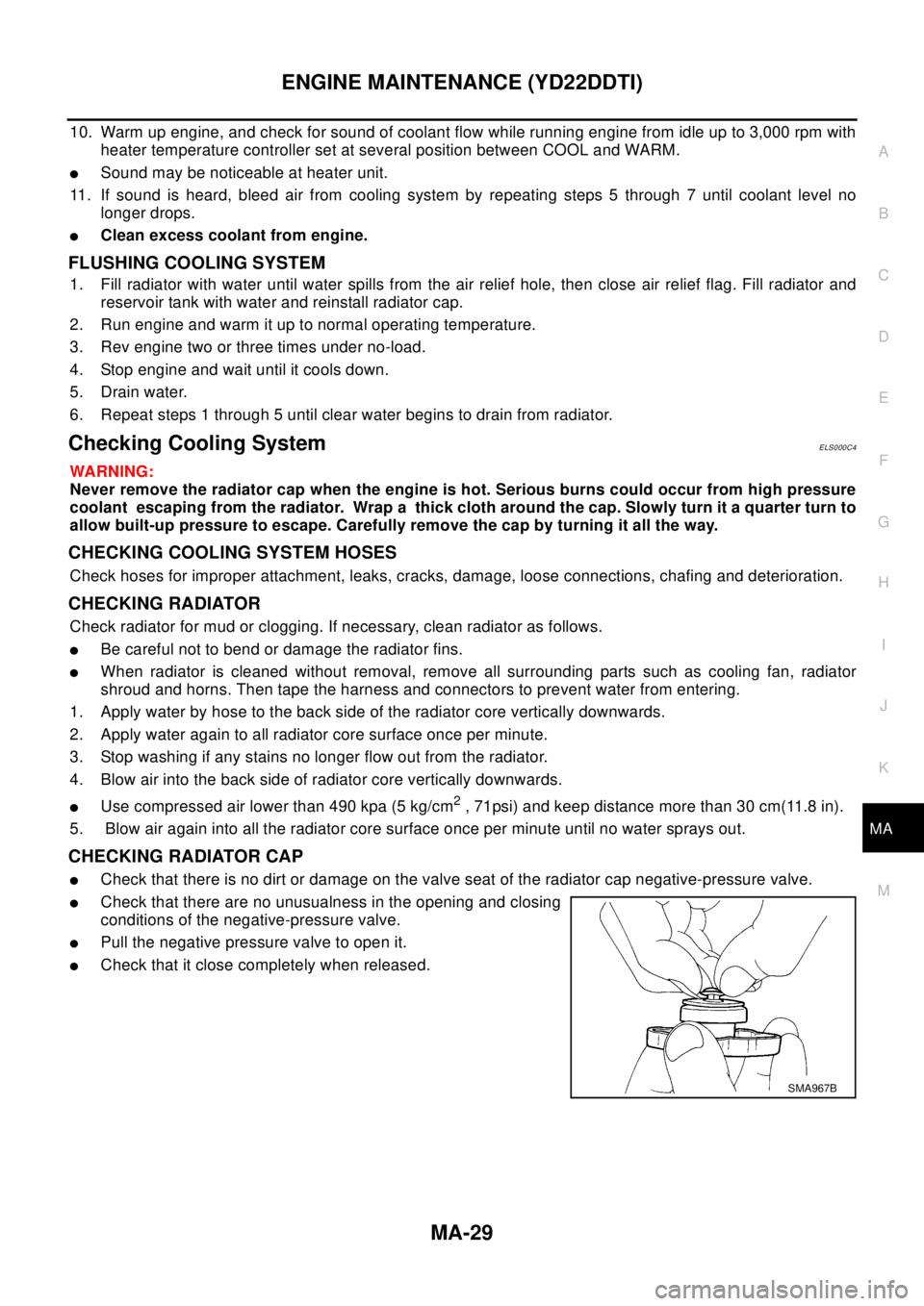
CHECKING RADIATOR CAP
lCheck that there is no dirt or damage on the valve seat of the radiator cap negative-pressure valve.
lCheck that there are no unusualness in the opening and closing
conditions of the negative-pressure valve.
lPull the negative pressure valve to open it.
lCheck that it close completely when released.
SMA967B
Page 2738 of 3066

PG-62
HARNESS
HO2S1H EC Heated Oxygen Sensor 1 (Front)
HO2S2 EC Heated Oxygen Sensor 1 (Rear)
HO2S2H EC Heated Oxygen Sensor 1 (Rear)
HORN WW Horn
IATS EC Intake Air Temperature Sensor
IATSEN EC Intake Air Temperature Sensor
IGNSYS EC Ignition Signal
ILL LT Illumination
INJECT EC Injector
INT/L LT Map Lamp
IVC EC Intake Valve Timing Control Solenoid Valve
IVC/V EC Intake Valve Timing Control Solenoid Valve
KS EC Knock Sensor (KS)
LOAD EC Electrical Load Signal
LPSV AT Line Pressure Solenoid Valve
MAFS EC MassAirFlowSensor(MAFS)
MAIN EC, AT Main Power Supply and Ground Circuit
METER DI Meter and Gauge
MIL EC Malfunction Indicator Lamp
MIL/DL EC MIL and Data Link Connector
MIRROR GW Door Mirror
MULTI BL Multi-Remote Control System
NATS BL Nissan Anti-Theft System
NONDTC AT Non-Detective Items
OVRCSV AT Overrun Clutch Solenoid Valve
PGC/V EC EVAP Canister Purge Volume Control Solenoid Valve
PHASE EC Camshaft Position Sensor (PHASE)
PNP/SW EC, AT Park/Neutral Position (PNP) Switch
PNPSW1 EC Park/Neutral Position (PNP) Switch
POS EC Crankshaft Position Sensor (CKPS)(POS)
POWER PG Power Supply Routing
PRGVLV EC EVAP Canister Purge Volume Control Solenoid Valve
PRWIRE BL Theft Warning System (Pre-wire)
PS/SEN EC Power Steering Pressure Sensor
PST/SW EC Power Steering Oil Pressure Switch
R/FOG LT Rear Fog Lamp
ROOM/L LT Interior Room Lamp
RP/SEN EC Refrigerant Pressure Sensor
RRO2 EC Heated Oxygen Sensor 2 (Rear)
RRO2/H EC Heated Oxygen Sensor 2 Heater (Rear)
S/LOCK BL Super Lock
S/SIG EC Start Signal
SCTC/V EC Suction Control Valve
SHIFT AT A/T Shift Lock System
SROOF BL Sunroof
SRS SRS Supplemental Restraint System (SRS)
SSV/A AT Shift Solenoid Valve A
SSV/B AT Shift Solenoid Valve B
START SC Starting System
STOP/L LT Stop Lamp
T/MTR EC Throttle Control Motor
TAIL/L LT Parking, License and Tail Lamps