4WD NISSAN X-TRAIL 2003 Electronic Workshop Manual
[x] Cancel search | Manufacturer: NISSAN, Model Year: 2003, Model line: X-TRAIL, Model: NISSAN X-TRAIL 2003Pages: 3066, PDF Size: 51.47 MB
Page 919 of 3066
![NISSAN X-TRAIL 2003 Electronic Workshop Manual ACTUATOR
BRC-51
[4WD/ABS]
C
D
E
G
H
I
J
K
L
MA
B
BRC
ACTUATORPFP:47600
Removal and InstallationEFS001CO
REMOVAL
Be careful of the following.
CAUTION:
lBefore servicing, disconnect battery terminals.
l](/img/5/57402/w960_57402-918.png "NISSAN X-TRAIL 2003 Electronic Workshop Manual ACTUATOR
BRC-51
[4WD/ABS]
C
D
E
G
H
I
J
K
L
MA
B
BRC
ACTUATORPFP:47600
Removal and InstallationEFS001CO
REMOVAL
Be careful of the following.
CAUTION:
lBefore servicing, disconnect battery terminals.
l")
ACTUATOR
BRC-51
[4WD/ABS]
C
D
E
G
H
I
J
K
L
MA
B
BRC
ACTUATORPFP:47600
Removal and InstallationEFS001CO
REMOVAL
Be careful of the following.
CAUTION:
lBefore servicing, disconnect battery terminals.
lTo remove brake tube, use a flare nut wrench to prevent flare nuts and brake tube from being dam-
aged. To install, use a flare nut torque wrench and tighten to the specified torque.
INSTALLATION
Be careful of the following.
lTighten mounting bolts and nuts to the specified torque.
lAfter the work, bleed the brakes. Refer toBR-10, "Bleeding Brake System".
SFIA0360E
Page 927 of 3066
![NISSAN X-TRAIL 2003 Electronic Workshop Manual CAN COMMUNICATION
BRC-59
[ESP/TCS/ABS]
C
D
E
G
H
I
J
K
L
MA
B
BRC
CAN COMMUNICATIONPFP:23710
System DescriptionEFS001CN
CAN (Controller Area Network) is a serial communication line for real time appli](/img/5/57402/w960_57402-926.png "NISSAN X-TRAIL 2003 Electronic Workshop Manual CAN COMMUNICATION
BRC-59
[ESP/TCS/ABS]
C
D
E
G
H
I
J
K
L
MA
B
BRC
CAN COMMUNICATIONPFP:23710
System DescriptionEFS001CN
CAN (Controller Area Network) is a serial communication line for real time appli")
CAN COMMUNICATION
BRC-59
[ESP/TCS/ABS]
C
D
E
G
H
I
J
K
L
MA
B
BRC
CAN COMMUNICATIONPFP:23710
System DescriptionEFS001CN
CAN (Controller Area Network) is a serial communication line for real time application. It is an on-vehicle mul-
tiplex communication line with high data communication speed and excellent error detection ability. Many elec-
tronic control units are equipped onto a vehicle, and each control unit shares information and links with other
control units during operation (not independent). In CAN communication, control units are connected with 2
communication lines (CAN H line, CAN L line) allowing a high rate of information transmission with less wiring.
Each control unit transmits/receives data but selectively reads required data only.
FOR M/T MODELS
System diagram
Input/output signal chart
T: Transmit R: Receive
SKIA0885E
Signals ECMSteering wheel
angle sensor4WD control unitESP/ TCS / ABS
control unit
Engine speed signal T R R
Accelerator pedal position signal T R
ESP operation signal R R T
TCS operation signal R R T
ABS operation signal R R T
Stop lamp switch signalRT
Steering wheel angle sensor signal T R
ESP-OFFSW signalRT
Wheel speed sensor signalRT
4WD Mode signalTR
Page 985 of 3066
![NISSAN X-TRAIL 2003 Electronic Workshop Manual TROUBLE DIAGNOSIS
BRC-117
[ESP/TCS/ABS]
C
D
E
G
H
I
J
K
L
MA
B
BRC
3.ECM SELF-DIAGNOSIS RESULT CHECK
Perform the ECM self-diagnosis.
Is the self-diagnosis results indicated?
YES >> Repair or replace t](/img/5/57402/w960_57402-984.png "NISSAN X-TRAIL 2003 Electronic Workshop Manual TROUBLE DIAGNOSIS
BRC-117
[ESP/TCS/ABS]
C
D
E
G
H
I
J
K
L
MA
B
BRC
3.ECM SELF-DIAGNOSIS RESULT CHECK
Perform the ECM self-diagnosis.
Is the self-diagnosis results indicated?
YES >> Repair or replace t")
TROUBLE DIAGNOSIS
BRC-117
[ESP/TCS/ABS]
C
D
E
G
H
I
J
K
L
MA
B
BRC
3.ECM SELF-DIAGNOSIS RESULT CHECK
Perform the ECM self-diagnosis.
Is the self-diagnosis results indicated?
YES >> Repair or replace the camshaft position sensor system.
NO >> GO TO 4.
4.SELF-DIAGNOSIS RESULT 2
Disconnect connectors for the ESP/TCS/ABS control unit and ECM, and reconnect them correctly to perform
the self-diagnosis again.
Is inspection result OK?
OK >> GO TO 5.
NG >> Connector malfunction. Repair or replace the connector.
5.SELF-DIAGNOSIS RESULT CHECK 3
Perform the 4WD control unit self-diagnosis.
Is inspection result OK?
OK >> GO TO 6.
NG >> Repair or replace the applicable part.
6.SELF-DIAGNOSIS RESULT CHECK 4
Perform the ESP/TCS/4WD control unit self-diagnosis again.
Is the self-diagnosis results displayed?
YES >> Repair or replace the applicable item.
NO >> GO TO 7.
7.CIRCUIT CHECK BETWEEN ESP/TCS/ABS CONTROL UNIT AND ECM
1. Disconnect connectors for the ESP/TCS/ABS control unit and ECM.
2. Check the engine speed signal harness between the ESP/TCS/ABS control unit and ECM for an open/
shorted circuit.
3. Check connectors for the ESP/TCS/ABS control unit and ECM.
Is inspection result OK?
OK >> Inspection End
NG >> Repair or replace the applicable item and perform the ESP/TCS/ABS control unit self-diagnosis
again.
Page 1059 of 3066
COMBINATION METERS (LHD MODELS)
DI-5
C
D
E
F
G
H
I
J
L
MA
B
DI
Diesel engine models
The water temperature gauge indicates the engine coolant temperature. The reading on the gauge is based
on the resistance of the thermal transmitter.
As the temperature of the coolant increases, the resistance of the thermal transmitter decreases. A variable
ground is supplied to terminal 55 of the combination meter for the water temperature gauge. The needle on
the gauge moves from “C” to “H”.
TACHOMETER
The tachometer indicates engine speed in revolutions per minute (rpm).
The tachometer is regulated by a signal
lfrom terminal 36 (Gasoline engine models) or D1 (Diesel engine models) of the ECM
lto combination meter terminal 54 for the tachometer.
FUEL GAUGE
The fuel gauge indicates the approximate fuel level in the fuel tank.
The fuel gauge is regulated by a variable ground signal supplied
lfrom body grounds, B8 and B18
lthrough terminal 1 and 3 of the Sub fuel level sensor unit and
lthrough terminal 4 and 1 of the fuel level sensor unit
lto combination meter terminal 51 for the fuel gauge.
SPEEDOMETER
The combination meter provides a voltage signal to the vehicle speed signal from 4WD/ABS control unit (with-
out ESP) or 4WD control unit (with ESP).
The voltage is supplied
lfrom combination meter terminal 42 for the speedometer
lto terminal 20 of 4WD/ABS control unit (without ESP) or 4WD control unit (without ESP).
The speedometer converts the voltage into the vehicle speed displayed.
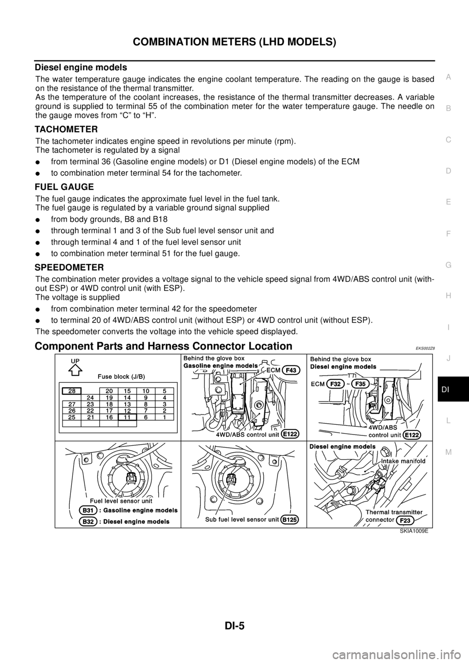
Component Parts and Harness Connector LocationEKS002Z8
SKIA1009E
Page 1068 of 3066
DI-14
COMBINATION METERS (LHD MODELS)
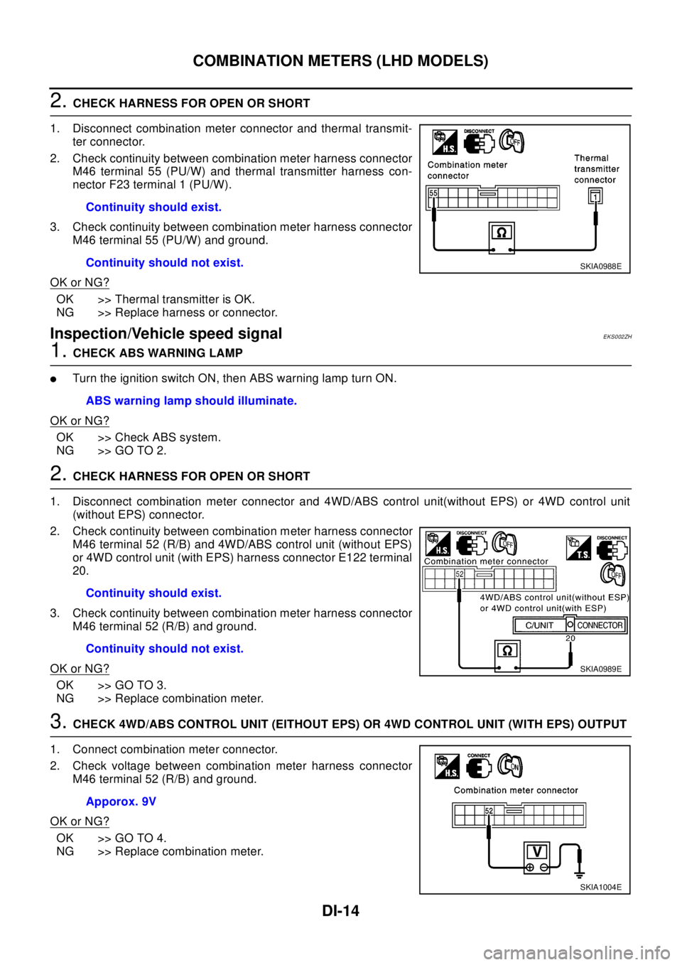
2.CHECK HARNESS FOR OPEN OR SHORT
1. Disconnect combination meter connector and thermal transmit-
ter connector.
2. Check continuity between combination meter harness connector
M46 terminal 55 (PU/W) and thermal transmitter harness con-
nector F23 terminal 1 (PU/W).
3. Check continuity between combination meter harness connector
M46 terminal 55 (PU/W) and ground.
OK or NG?
OK >> Thermal transmitter is OK.
NG >> Replace harness or connector.
Inspection/Vehicle speed signalEKS002ZH
1.CHECK ABS WARNING LAMP
lTurntheignitionswitchON,thenABSwarninglampturnON.
OK or NG?
OK >> Check ABS system.
NG >> GO TO 2.
2.CHECK HARNESS FOR OPEN OR SHORT
1. Disconnect combination meter connector and 4WD/ABS control unit(without EPS) or 4WD control unit
(without EPS) connector.
2. Check continuity between combination meter harness connector
M46 terminal 52 (R/B) and 4WD/ABS control unit (without EPS)
or 4WD control unit (with EPS) harness connector E122 terminal
20.
3. Check continuity between combination meter harness connector
M46 terminal 52 (R/B) and ground.
OK or NG?
OK >> GO TO 3.
NG >> Replace combination meter.
3.CHECK 4WD/ABS CONTROL UNIT (EITHOUT EPS) OR 4WD CONTROL UNIT (WITH EPS) OUTPUT
1. Connect combination meter connector.
2. Check voltage between combination meter harness connector
M46 terminal 52 (R/B) and ground.
OK or NG?
OK >> GO TO 4.
NG >> Replace combination meter.Continuity should exist.
Continuity should not exist.
SKIA0988E
ABS warning lamp should illuminate.
Continuity should exist.
Continuity should not exist.
SKIA0989E
Apporox. 9V
SKIA1004E
Page 1069 of 3066
COMBINATION METERS (LHD MODELS)
DI-15
C
D
E
F
G
H
I
J
L
MA
B
DI
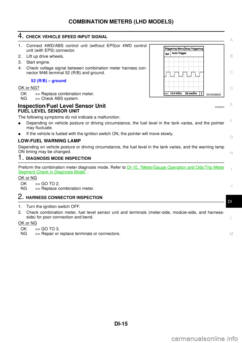
4.CHECK VEHICLE SPEED INPUT SIGNAL
1. Connect 4WD/ABS control unit (without EPS)or 4WD control
unit (with EPS) connector.
2. Lift up drive wheels.
3. Start engine.
4. Check voltage signal between combination meter harness con-
nector M46 terminal 52 (R/B) and ground.
OK or NG?
OK >> Replace combination meter.
NG >> Check ABS system.
Inspection/Fuel Level Sensor UnitEKS002ZI
FUEL LEVEL SENSOR UNIT
The following symptoms do not indicate a malfunction.
lDepending on vehicle posture or driving circumstance, the fuel level in the tank varies, and the pointer
may fluctuate.
lIf the vehicle is fueled with the ignition switch ON, the pointer will move slowly.
LOW-FUEL WARNING LAMP
Depending on vehicle posture or driving circumstance, the fuel level in the tank varies, and the warning lamp
ON timing may be changed.
1.DIAGNOSIS MODE INSPECTION
Preform the combination meter diagnosis mode. Refer toDI-10, "
Meter/Gauge Operation and Odo/Trip Meter
Segment Check in Diagnosis Mode".
OK or NG
OK >> GO TO 2.
NG >> Replace combination meter.
2.HARNESS CONNECTOR INSPECTION
1. Turn the ignition switch OFF.
2. Check combination meter, fuel level sensor unit and terminals (meter-side, module-side, and harness-
side) for poor connection and bend.
OK or NG
OK >> GO TO 3.
NG >> Repair or replace terminals or connectors.52 (R/B) – ground
SKIA0990E
Page 1077 of 3066
COMBINATION METERS (RHD MODELS)
DI-23
C
D
E
F
G
H
I
J
L
MA
B
DI
Diesel engine models
The water temperature gauge indicates the engine coolant temperature. The reading on the gauge is based
on the resistance of the thermal transmitter.
As the temperature of the coolant increases, the resistance of the thermal transmitter decreases. A variable
ground is supplied to terminal 66 of the combination meter for the water temperature gauge. The needle on
the gauge moves from “C” to “H”.
TACHOMETER
The tachometer indicates engine speed in revolutions per minute (rpm).
The tachometer is regulated by a signal
lfrom terminal 36 (Gasoline engine models) or D1 (Diesel engine models) of the ECM
lto combination meter terminal 41 for the tachometer.
FUEL GAUGE
The fuel gauge indicates the approximate fuel level in the fuel tank.
The fuel gauge is regulated by a variable ground signal supplied
lfrom body grounds , B107 and B119
lthrough terminal 1 and 3 of the Sub fuel level sensor unit and
lthrough terminal 4 and 1 of the fuel level sensor unit
lto combination meter terminal 40 for the fuel gauge.
SPEEDOMETER
The combination meter provides a voltage signal to the vehicle speed signal from 4WD/ABS control unit (with-
out ESP) or 4WD control unit (with ESP).
The voltage is supplied
lfrom combination meter terminal 42 for the speedometer
lto terminal 20 of 4WD/ABS control unit (without ESP) or 4WD control unit (with ESP).
The speedometer converts the voltage into the vehicle speed displayed.
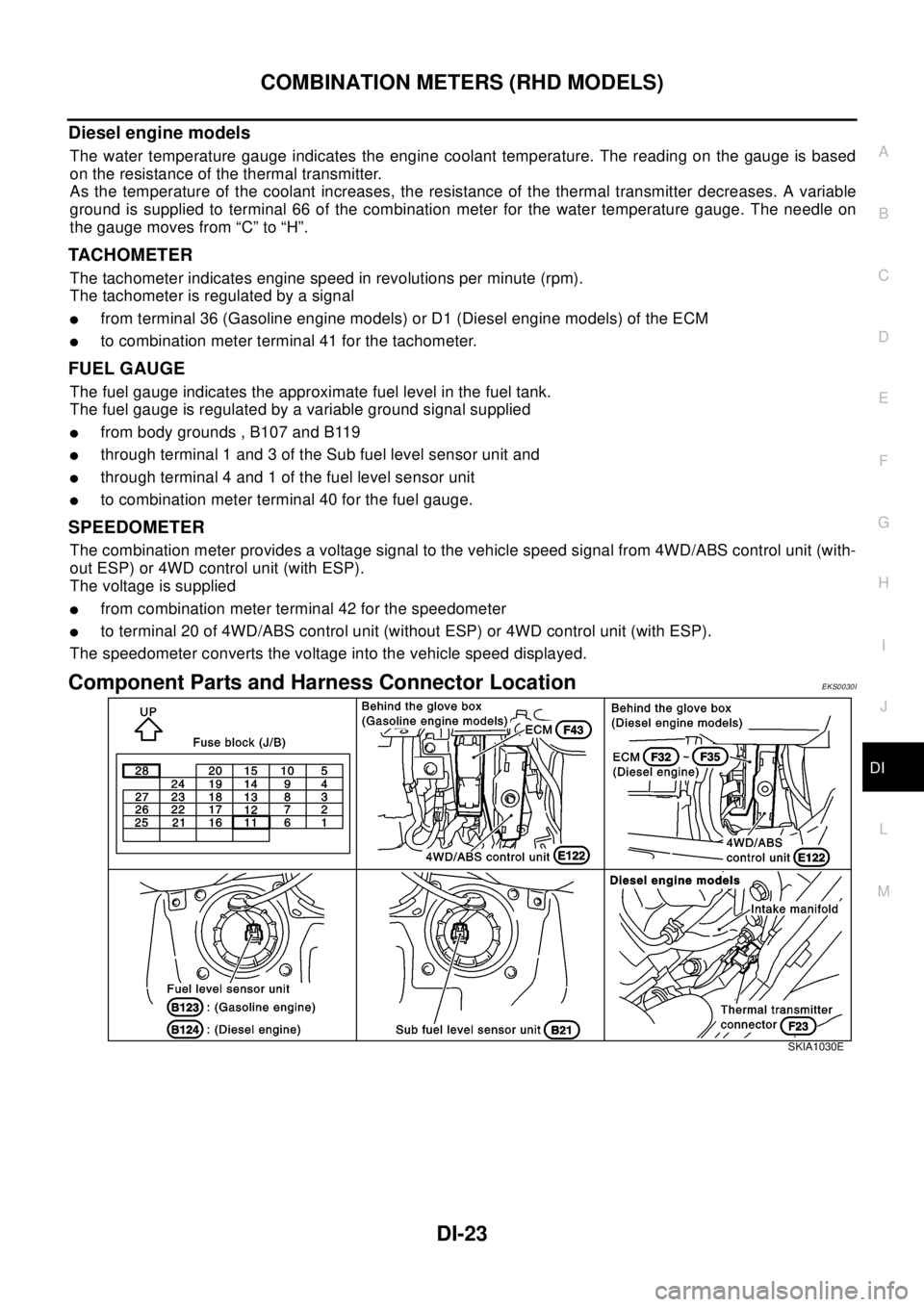
Component Parts and Harness Connector LocationEKS0030I
SKIA1030E
Page 1086 of 3066
DI-32
COMBINATION METERS (RHD MODELS)
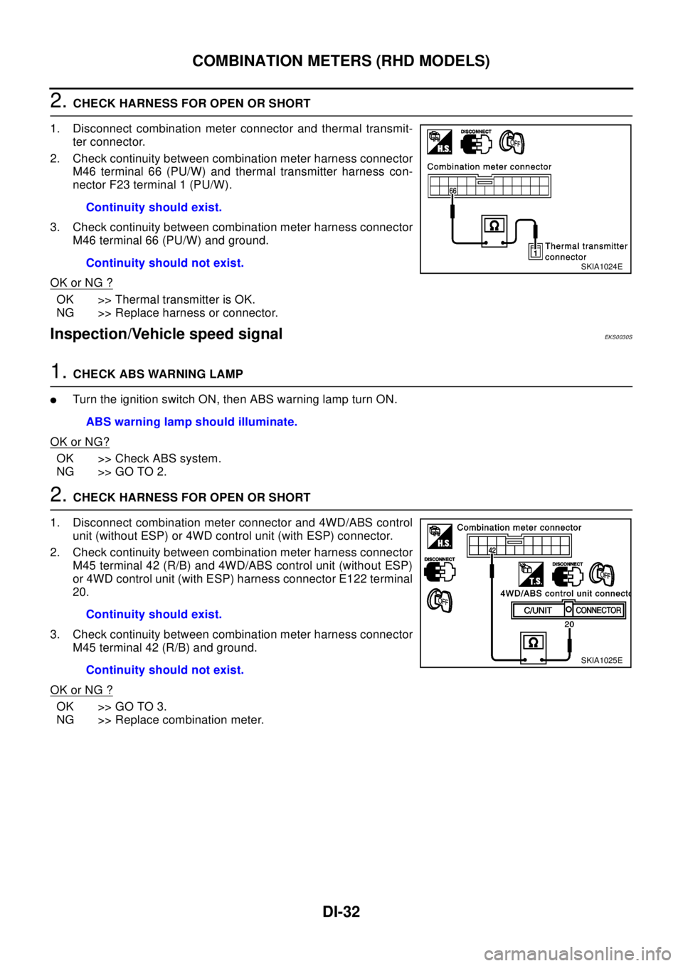
2.CHECK HARNESS FOR OPEN OR SHORT
1. Disconnect combination meter connector and thermal transmit-
ter connector.
2. Check continuity between combination meter harness connector
M46 terminal 66 (PU/W) and thermal transmitter harness con-
nector F23 terminal 1 (PU/W).
3. Check continuity between combination meter harness connector
M46 terminal 66 (PU/W) and ground.
OK or NG ?
OK >> Thermal transmitter is OK.
NG >> Replace harness or connector.
Inspection/Vehicle speed signalEKS0030S
1.CHECK ABS WARNING LAMP
lTurntheignitionswitchON,thenABSwarninglampturnON.
OK or NG?
OK >> Check ABS system.
NG >> GO TO 2.
2.CHECK HARNESS FOR OPEN OR SHORT
1. Disconnect combination meter connector and 4WD/ABS control
unit (without ESP) or 4WD control unit (with ESP) connector.
2. Check continuity between combination meter harness connector
M45 terminal 42 (R/B) and 4WD/ABS control unit (without ESP)
or 4WD control unit (with ESP) harness connector E122 terminal
20.
3. Check continuity between combination meter harness connector
M45 terminal 42 (R/B) and ground.
OK or NG ?
OK >> GO TO 3.
NG >> Replace combination meter.Continuity should exist.
Continuity should not exist.
SKIA1024E
ABS warning lamp should illuminate.
Continuity should exist.
Continuity should not exist.
SKIA1025E
Page 1087 of 3066
COMBINATION METERS (RHD MODELS)
DI-33
C
D
E
F
G
H
I
J
L
MA
B
DI
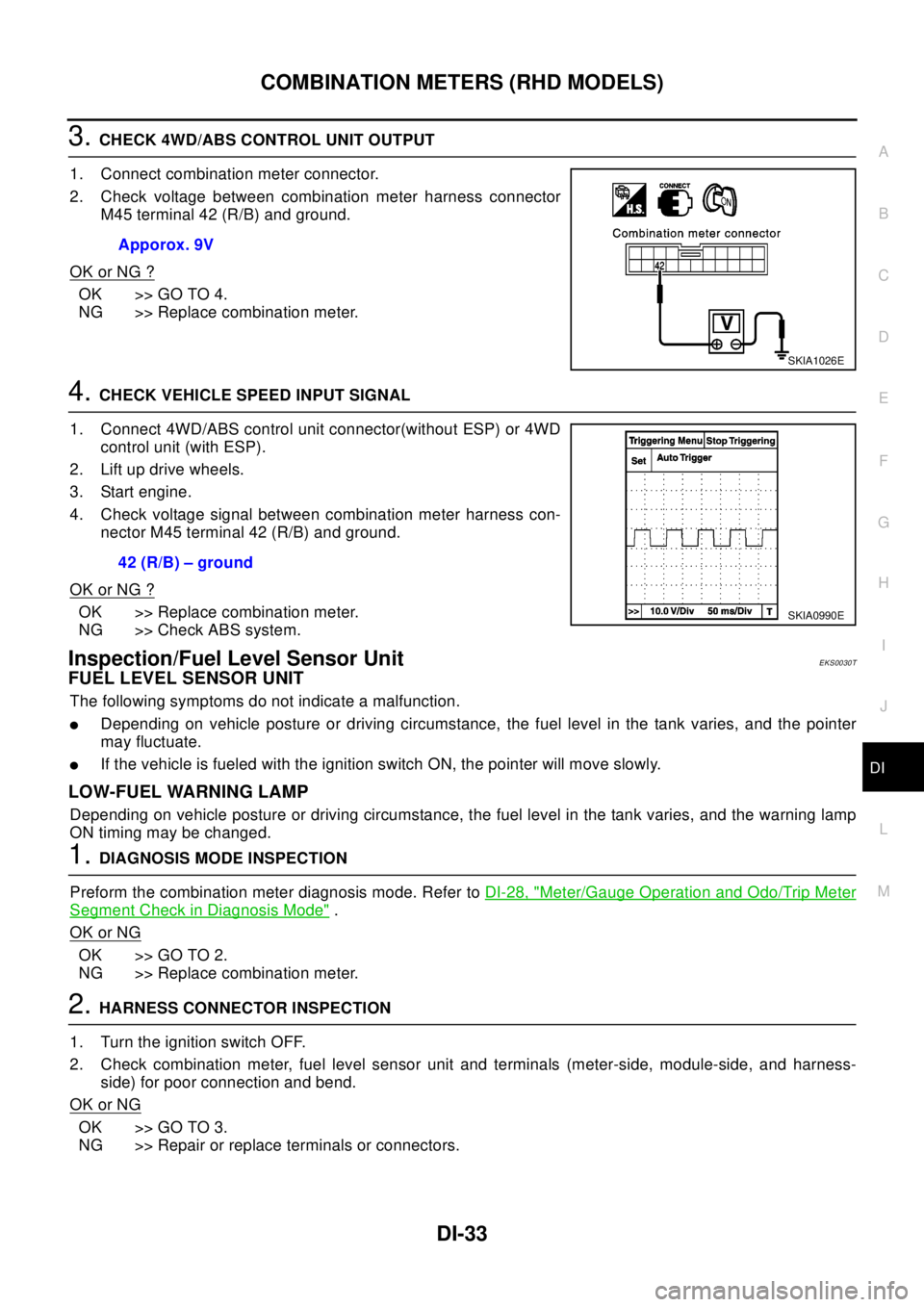
3.CHECK 4WD/ABS CONTROL UNIT OUTPUT
1. Connect combination meter connector.
2. Check voltage between combination meter harness connector
M45 terminal 42 (R/B) and ground.
OK or NG ?
OK >> GO TO 4.
NG >> Replace combination meter.
4.CHECK VEHICLE SPEED INPUT SIGNAL
1. Connect 4WD/ABS control unit connector(without ESP) or 4WD
control unit (with ESP).
2. Lift up drive wheels.
3. Start engine.
4. Check voltage signal between combination meter harness con-
nector M45 terminal 42 (R/B) and ground.
OK or NG ?
OK >> Replace combination meter.
NG >> Check ABS system.
Inspection/Fuel Level Sensor UnitEKS0030T
FUEL LEVEL SENSOR UNIT
The following symptoms do not indicate a malfunction.
lDepending on vehicle posture or driving circumstance, the fuel level in the tank varies, and the pointer
may fluctuate.
lIf the vehicle is fueled with the ignition switch ON, the pointer will move slowly.
LOW-FUEL WARNING LAMP
Depending on vehicle posture or driving circumstance, the fuel level in the tank varies, and the warning lamp
ON timing may be changed.
1.DIAGNOSIS MODE INSPECTION
Preform the combination meter diagnosis mode. Refer toDI-28, "
Meter/Gauge Operation and Odo/Trip Meter
Segment Check in Diagnosis Mode".
OK or NG
OK >> GO TO 2.
NG >> Replace combination meter.
2.HARNESS CONNECTOR INSPECTION
1. Turn the ignition switch OFF.
2. Check combination meter, fuel level sensor unit and terminals (meter-side, module-side, and harness-
side) for poor connection and bend.
OK or NG
OK >> GO TO 3.
NG >> Repair or replace terminals or connectors.Apporox. 9V
SKIA1026E
42 (R/B) – ground
SKIA0990E
Page 1143 of 3066
![NISSAN X-TRAIL 2003 Electronic Workshop Manual ENGINE CONTROL SYSTEM
EC-29
[QR (WITH EURO-OBD)]
C
D
E
F
G
H
I
J
K
L
MA
ECFOR M/T MODELS
System Diagram
Input/Output Signal Chart
T: Transmit R: Receive Accelerator pedal position signal T R
A/T self-](/img/5/57402/w960_57402-1142.png "NISSAN X-TRAIL 2003 Electronic Workshop Manual ENGINE CONTROL SYSTEM
EC-29
[QR (WITH EURO-OBD)]
C
D
E
F
G
H
I
J
K
L
MA
ECFOR M/T MODELS
System Diagram
Input/Output Signal Chart
T: Transmit R: Receive Accelerator pedal position signal T R
A/T self-")
ENGINE CONTROL SYSTEM
EC-29
[QR (WITH EURO-OBD)]
C
D
E
F
G
H
I
J
K
L
MA
ECFOR M/T MODELS
System Diagram
Input/Output Signal Chart
T: Transmit R: Receive Accelerator pedal position signal T R
A/T self-diagnosis signal R TSignals ECM TCM
SKIA0885E
Signals ECMSteering wheel
angle sensor4WD control unitESP/ TCS / ABS
control unit
Engine speed signal T R R
Accelerator pedal position signal T R
ESP operation signal R R T
TCS operation signal R R T
ABS operation signal R R T
Stop lamp switch signalRT
Steering wheel angle sensor signal T R
ESP-OFFSW signalRT
Wheel speed sensor signalRT
4WD Mode signalTR