4WD NISSAN X-TRAIL 2003 Electronic Manual Online
[x] Cancel search | Manufacturer: NISSAN, Model Year: 2003, Model line: X-TRAIL, Model: NISSAN X-TRAIL 2003Pages: 3066, PDF Size: 51.47 MB
Page 2396 of 3066
![NISSAN X-TRAIL 2003 Electronic Manual Online LAN-20
[CAN]
CAN SYSTEM (FOR M/T MODELS)
CAN Communication Circuit Check
EKS002LE
1.CHECK CONNECTOR
1. Turn ignition switch OFF.
2. Check following terminals and connector for damage, bend and loose c](/img/5/57402/w960_57402-2395.png "NISSAN X-TRAIL 2003 Electronic Manual Online LAN-20
[CAN]
CAN SYSTEM (FOR M/T MODELS)
CAN Communication Circuit Check
EKS002LE
1.CHECK CONNECTOR
1. Turn ignition switch OFF.
2. Check following terminals and connector for damage, bend and loose c")
LAN-20
[CAN]
CAN SYSTEM (FOR M/T MODELS)
CAN Communication Circuit Check
EKS002LE
1.CHECK CONNECTOR
1. Turn ignition switch OFF.
2. Check following terminals and connector for damage, bend and loose connection. (control module-side,
control unit-side, sensor-side and harness-side)
lESP/TCS/ABS control unit.
l4WD control unit.
lSteering wheel angle sensor.
lECM.
lBetween ESP/TCS/ABS control unit and ECM.
OK or NG
OK >> GO TO 2.
NG >> Repair terminal or connector.
2.CHECK HARNESS FOR SHORT CIRCUIT
1. Disconnect ESP/TCS/ABS control unit connector and harness connector B103.
2. Check continuity between ESP/TCS/ABS control unit harness
connector B111 terminals 61 (W) and 63(R).
OK or NG
OK >> GO TO 3.
NG >> Repair harness between harness connector B103 and
ESP/TCS/ABS control unit.
3.CHECK HARNESS FOR SHORT CIRCUIT
Check continuity between ESP/TCS/ABS control unit harness con-
nector B111 terminals 61 (W), 63(R) and ground.
OK or NG
OK >> GO TO 4.
NG >> Repair harness between harness connector B103 and
ESP/TCS/ABS control unit. 61(W) – 63(R) : Continuity should not exist.
SKIA1288E
61(W) – ground : Continuity should not exist.
63(R) – ground : Continuity should not exist.
SKIA1289E
Page 2397 of 3066
![NISSAN X-TRAIL 2003 Electronic Manual Online CAN SYSTEM (FOR M/T MODELS)
LAN-21
[CAN]
C
D
E
F
G
H
I
J
L
MA
B
LAN
4.CHECK HARNESS FOR SHORT CIRCUIT
1. Disconnect 4WD control unit connector and harness connector E116.
2. Check continuity between 4](/img/5/57402/w960_57402-2396.png "NISSAN X-TRAIL 2003 Electronic Manual Online CAN SYSTEM (FOR M/T MODELS)
LAN-21
[CAN]
C
D
E
F
G
H
I
J
L
MA
B
LAN
4.CHECK HARNESS FOR SHORT CIRCUIT
1. Disconnect 4WD control unit connector and harness connector E116.
2. Check continuity between 4")
CAN SYSTEM (FOR M/T MODELS)
LAN-21
[CAN]
C
D
E
F
G
H
I
J
L
MA
B
LAN
4.CHECK HARNESS FOR SHORT CIRCUIT
1. Disconnect 4WD control unit connector and harness connector E116.
2. Check continuity between 4WD control unit harness connector
E122 terminals 48 (W) and 39(R).
OK or NG
OK >> GO TO 5.
NG >>
lRepair harness between harness connector E116 and
harness connector E119.
lRepair harness between harness connector E116 and
4WD control unit.
5.CHECK HARNESS FOR SHORT CIRCUIT
Check continuity between 4WD control unit harness connector E122
terminals 48 (W), 39(R) and ground.
OK or NG
OK >> GO TO 6.
NG >>
lRepair harness between harness connector E116 and
harness connector E119.
lRepair harness between harness connector E116 and
4WD control unit.
6.CHECK HARNESS FOR SHORT CIRCUIT
1. Disconnect steering wheel angle sensor connector and harness connector M61.
2. Check continuity between steering wheel angle sensor harness
connector M81 terminals 4 (W) and 5(R).
OK or NG
OK >> GO TO 7.
NG >>
lRepair harness between harness connector M75 and
harness connector M61.
lRepair harness between steering wheel angle sensor
and harness connector M61.
7.CHECK HARNESS FOR SHORT CIRCUIT
Check continuity between steering wheel angle sensor harness con-
nector M81 terminals 4 (W), 5 (R) and ground.
OK or NG
OK >> GO TO 8.
NG >>
lRepair harness between harness connector M75 and
harness connector M61.
lRepair harness between steering wheel angle sensor
and harness connector M61. 48(W) – 39(R) : Continuity should not exist.
SKIA0930E
48(W) – ground : Continuity should not exist.
39(R) – ground : Continuity should not exist.
SKIA0931E
4(W) – 5(R) : Continuity should not exist.
PKIA0281E
4(W) – ground : Continuity should not exist.
5(R) – ground : Continuity should not exist.
SKIA0932E
Page 2398 of 3066
![NISSAN X-TRAIL 2003 Electronic Manual Online LAN-22
[CAN]
CAN SYSTEM (FOR M/T MODELS)
8.CHECK HARNESS FOR SHORT CIRCUIT
1. Disconnect ECM connector.
2. Check continuity between ECM harness connector F43 termi-
nals 33 (W) and 34(R).
OK or NG
OK](/img/5/57402/w960_57402-2397.png "NISSAN X-TRAIL 2003 Electronic Manual Online LAN-22
[CAN]
CAN SYSTEM (FOR M/T MODELS)
8.CHECK HARNESS FOR SHORT CIRCUIT
1. Disconnect ECM connector.
2. Check continuity between ECM harness connector F43 termi-
nals 33 (W) and 34(R).
OK or NG
OK")
LAN-22
[CAN]
CAN SYSTEM (FOR M/T MODELS)
8.CHECK HARNESS FOR SHORT CIRCUIT
1. Disconnect ECM connector.
2. Check continuity between ECM harness connector F43 termi-
nals 33 (W) and 34(R).
OK or NG
OK >> GO TO 9.
NG >> Repair harness between ECM and harness connector
F41.
9.CHECK HARNESS FOR SHORT CIRCUIT
Check continuity between ECM harness connector F43 terminals 33
(W), 34 (R) and ground.
OK or NG
OK >> GO TO 10.
NG >> Repair harness between ECM and harness connector
F41.
10.ECM / ESP/TCS/ABS CONTROL UNIT INTERNAL CIRCUIT INSPECTION
Check components inspection. Refer toLAN-22, "
ECM / ESP/TCS/ABS CONTROL UNIT INTERNAL CIR-
CUIT INSPECTION"
OK or NG
OK >> Reconnect all connectors to perform “SELF-DIAG RESULTS” and “DATA MONITOR” for
“ENGINE”, “ALL MODE 4WD”, and “ABS” displayed on CONSULT-II. Refer toEC-114, "
DTC
U1000 CAN COMMUNICATION LINE"(WITH EURO-OBD) orEC-460, "DTC U1000 CAN COM-
MUNICATION LINE"(WITHOUT EURO-OBD) for “ENGINE” and Refer toTF-53, "CAN COMMU-
NICATION SYSTEM"for “ALL MODE 4WD”. Refer toBRC-108, "Inspection 15 CAN
Communication Circuit, ESP/TCS/ABS Control Unit and Steering Angle Sensor"for “ABS”.
NG >> Replace ECM and/or ESP/TCS/ABS control unit.
Component InspectionEKS002FW
ECM / ESP/TCS/ABS CONTROL UNIT INTERNAL CIRCUIT INSPECTION
lRemove ECM and ESP/TCS/ABS control unit from vehicle.
lCheck resistance between ECM terminals 33 and 34.
lCheck resistance between ESP/TCS/ABS control unit terminals
61 and 63.33(W) – 34(R) : Continuity should not exist.
SKIA0888E
33(W) – ground : Continuity should not exist.
34(R) – ground : Continuity should not exist.
SKIA0889E
Unit Terminal Resistance value (W)
ECM 33 – 34
Approx. 108 - 132
ESP/TCS/ABS control unit 61 – 63
SKIA0933E
Page 2443 of 3066
![NISSAN X-TRAIL 2003 Electronic Manual Online ILLUMINATION
LT-45
C
D
E
F
G
H
I
J
L
MA
B
LT
ILLUMINATIONPFP:27545
System DescriptionEKS003C7
Power is supplied at all times
lthrough 10A fuse [No. 31, located in the fuse and fusible link box]
lto li](/img/5/57402/w960_57402-2442.png "NISSAN X-TRAIL 2003 Electronic Manual Online ILLUMINATION
LT-45
C
D
E
F
G
H
I
J
L
MA
B
LT
ILLUMINATIONPFP:27545
System DescriptionEKS003C7
Power is supplied at all times
lthrough 10A fuse [No. 31, located in the fuse and fusible link box]
lto li")
ILLUMINATION
LT-45
C
D
E
F
G
H
I
J
L
MA
B
LT
ILLUMINATIONPFP:27545
System DescriptionEKS003C7
Power is supplied at all times
lthrough 10A fuse [No. 31, located in the fuse and fusible link box]
lto lighting switch terminal 11.
The lighting switch must be in the 1ST or 2ND position for illumination.
The following chart shows the power and ground connector terminals for the components included in the illu-
mination system.
Component Connector No. Power terminal Ground terminal
Headlamp washier switch M23 3 4
Headlamp aiming switch M24 3 4
Door mirror remote control
switchM26 10 1
VDC off switch M25 3 4
Hazard switch M51 7 8
4WD mode switch M39 4 3
Rear window defogger switch M50 5 6
A/C auto amp. M52 12 11
Combination meter
(LHD models)M46 56 66
Combination meter
(RHD models)M46 45 56
Audio M42 2 1
CD auto changer M82 34 35
Heater control panel M55 2 6
A/T device M58 3 4
Cigarette lighter M56 3 2
Heated seat switch LH
(LHD models)B131 5 6
Heated seat switch RH
(LHD models)B132 5 6
Heated seat switch LH
(RHD models)B35 5 6
Heated seat switch RH
(RHD models)B34 5 6
Page 2548 of 3066
MT-12
SIDE OIL SEAL
SIDE OIL SEAL
PFP:32113
Removal and InstallationECS001WS
REMOVAL
lClutch housing side oil seal used on 4WD vehicles is attached to the transfer. Be sure to replace it
when transfer is removed.
1. Remove the driveshaft from the transaxle.
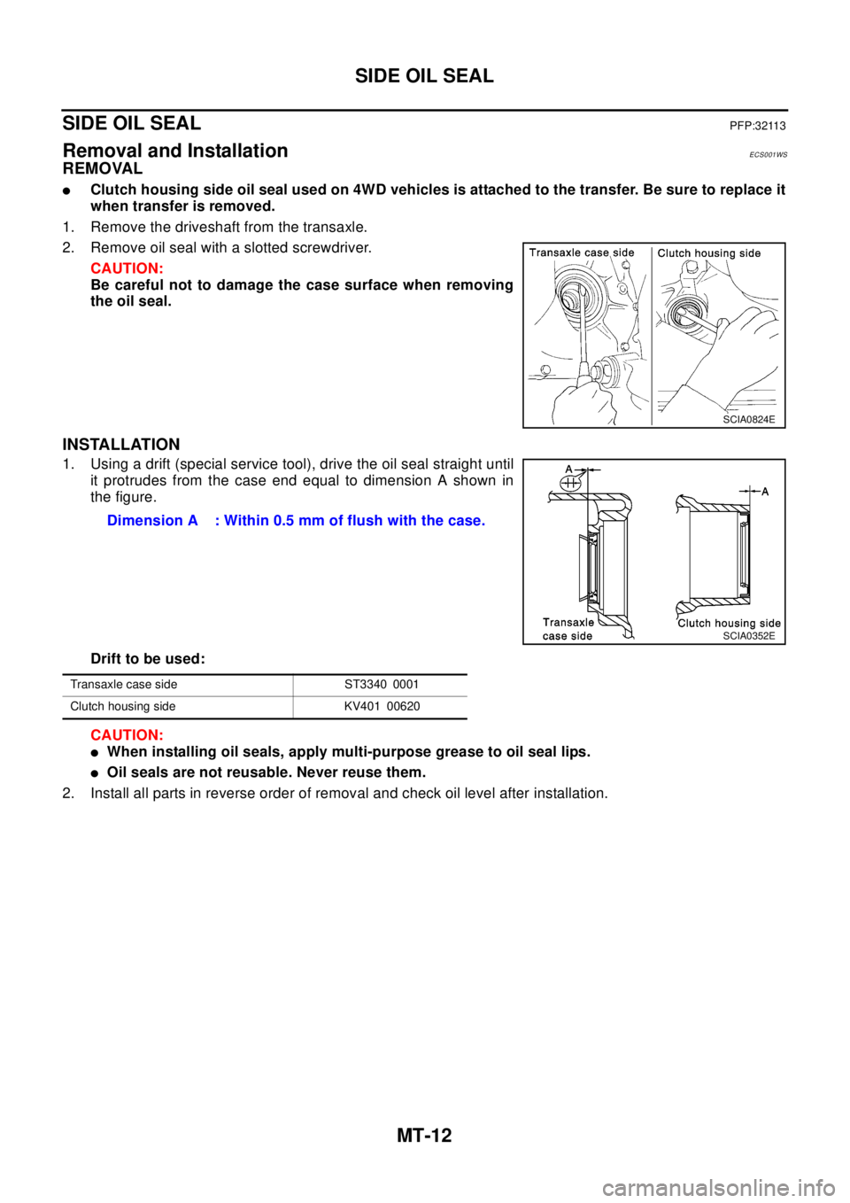
2. Remove oil seal with a slotted screwdriver.
CAUTION:
Be careful not to damage the case surface when removing
the oil seal.
INSTALLATION
1. Using a drift (special service tool), drive the oil seal straight until
it protrudes from the case end equal to dimension A shown in
the figure.
Drift to be used:
CAUTION:
lWhen installing oil seals, apply multi-purpose grease to oil seal lips.
lOil seals are not reusable. Never reuse them.
2. Install all parts in reverse order of removal and check oil level after installation.
SCIA0824E
Dimension A : Within 0.5 mm of flush with the case.
SCIA0352E
Transaxle case side ST3340 0001
Clutch housing side KV401 00620
Page 2737 of 3066

HARNESS
PG-61
C
D
E
F
G
H
I
J
L
MA
B
PG
Wiring Diagram Codes (Cell Codes)EKS0032J
Use the chart below to find out what each wiring diagram code stands for.
Refer to the wiring diagram code in the alphabetical index to find the location (page number) of each wiring
diagram.
Code Section Wiring Diagram Name
1STSIG AT A/T 1st Signal
2NDSIG AT A/T 2nd Signal
3RDSIG AT A/T 3rd Signal
4THSIG AT A/T 4th Signal
4WD BRC 4WD Control system
A/C ATC Air Conditioner
ABS BRC ABS Control System
APPS EC Accelerator Pedal Position (APP) Sensor
APRSW EC Accelerator Pedal Released Position Sensor
AT/IND DI A/T Indicator
AUDIO AV Audio
BA/FTS AT A/T Fluid Temperature Sensor and TCM Power Supply
BACK/L LT Back-up Lamp
BRK/SW EC Brake Switch
CAN EC,AT CAN Communication Line
CAN LAN CAN System
CHARGE SC Charging System
CHIME DI Warning Chime
CIGAR WW Cigarette Lighter
CLOCK DI Clock
CKPS EC Crankshaft Position Sensor
CMPS EC Camshaft Position Sensor
COOL/F EC Cooling Fan Control
CRFPS EC Common Rail Fuel Pressure Sensor
D/LOCK BL Power Door Lock
DEF GW Rear Window Defogger
DTRL LT Headlamp - With Daytime Light System
ECM/PW EC ECM Power
ECMRLY EC ECM Relay
ECTS EC Engine Coolant Temperature Sensor
EGRC/V EC EGR Volume Control Valve
ENGSS AT Engine Speed Signal
F/FOG LT Front Fog Lamp
FIAR EC Fuel Injector Adjustment resister
FRO2 EC Heated Oxygen Sensor 1 (Front)
FRO2/H EC Heated Oxygen Sensor 1 Heater (Front)
FTS EC Fuel Temperature Sensor
FTS AT A/T Fluid Temperature Sensor
FUEL EC Fuel Injection System Function
GLOW EC Glow Control System
H/AIM LT Headlamp Aiming Control System
H/LAMP LT Headlamp
H/SEAT SE Heated Seat
HEATER MTC Heater System
HLC WW Headlamp Cleaner
HO2S1 EC Heated Oxygen Sensor 1 (Front)
Page 2797 of 3066

RAX-1
REAR AXLE
D DRIVELINE/AXLE
CONTENTS
C
E
F
G
H
I
J
K
L
M
SECTION
A
B
RAX
REAR AXLE
PRECAUTIONS .......................................................... 2
Caution ..................................................................... 2
Precautions for Brake System .................................. 2
PREPARATION ........................................................... 3
Special Service Tools ............................................... 3
Commercial Service Tools ........................................ 4
NOISE, VIBRATION, AND HARSHNESS (NVH)
TROUBLESHOOTING ................................................ 5
NVH Troubleshooting Chart ..................................... 5
WHEEL HUB (4WD) ................................................... 6
On-Vehicle Inspection .............................................. 6
REAR WHEEL BEARING ..................................... 6
Removal and Installation .......................................... 6
REMOVAL ............................................................. 6INSTALLATION ..................................................... 7
Disassembly and Assembly ...................................... 7
DISASSEMBLY ..................................................... 7
INSPECTION AFTER DISASSEMBLY .................. 8
ASSEMBLY ........................................................... 8
REAR DRIVE SHAFT ................................................. 9
Removal and Installation .......................................... 9
REMOVAL ............................................................. 9
INSPECTION AFTER REMOVAL ......................... 9
INSTALLATION ..................................................... 9
Disassembly and Assembly .................................... 10
DISASSEMBLY ................................................... 10
INSPECTION AFTER DISASSEMBLY ................ 11
ASSEMBLY ......................................................... 12
SERVICE DATA AND SPECIFICATIONS (SDS) ...... 15
Wheel Bearing ........................................................ 15
Drive Shaft .............................................................. 15
Page 2802 of 3066
RAX-6
WHEEL HUB (4WD)
WHEEL HUB (4WD)
PFP:43202
On-Vehicle InspectionEDS00065
Inspect to check that there is no excessive play, cracking, wear, or other damage to rear axle.
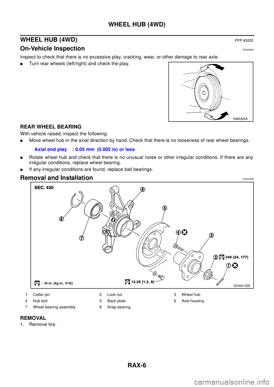
lTurn rear wheels (left/right) and check the play.
REAR WHEEL BEARING
With vehicle raised, inspect the following.
lMove wheel hub in the axial direction by hand. Check that there is no looseness of rear wheel bearings.
lRotate wheel hub and check that there is no unusual noise or other irregular conditions. If there are any
irregular conditions, replace wheel bearing.
lIf any irregular conditions are found, replace ball bearings.
Removal and InstallationEDS00066
REMOVAL
1. Remove tire.
SMA525A
Axial end play : 0.05 mm (0.002 in) or less
SDIA0132E
1 Cotter pin 2 Lock nut 3 Wheel hub
4 Hub bolt 5 Back plate 6 Axle housing
7 Wheel bearing assembly 8 Snap bearing
Page 2803 of 3066
WHEEL HUB (4WD)
RAX-7
C
E
F
G
H
I
J
K
L
MA
B
RAX
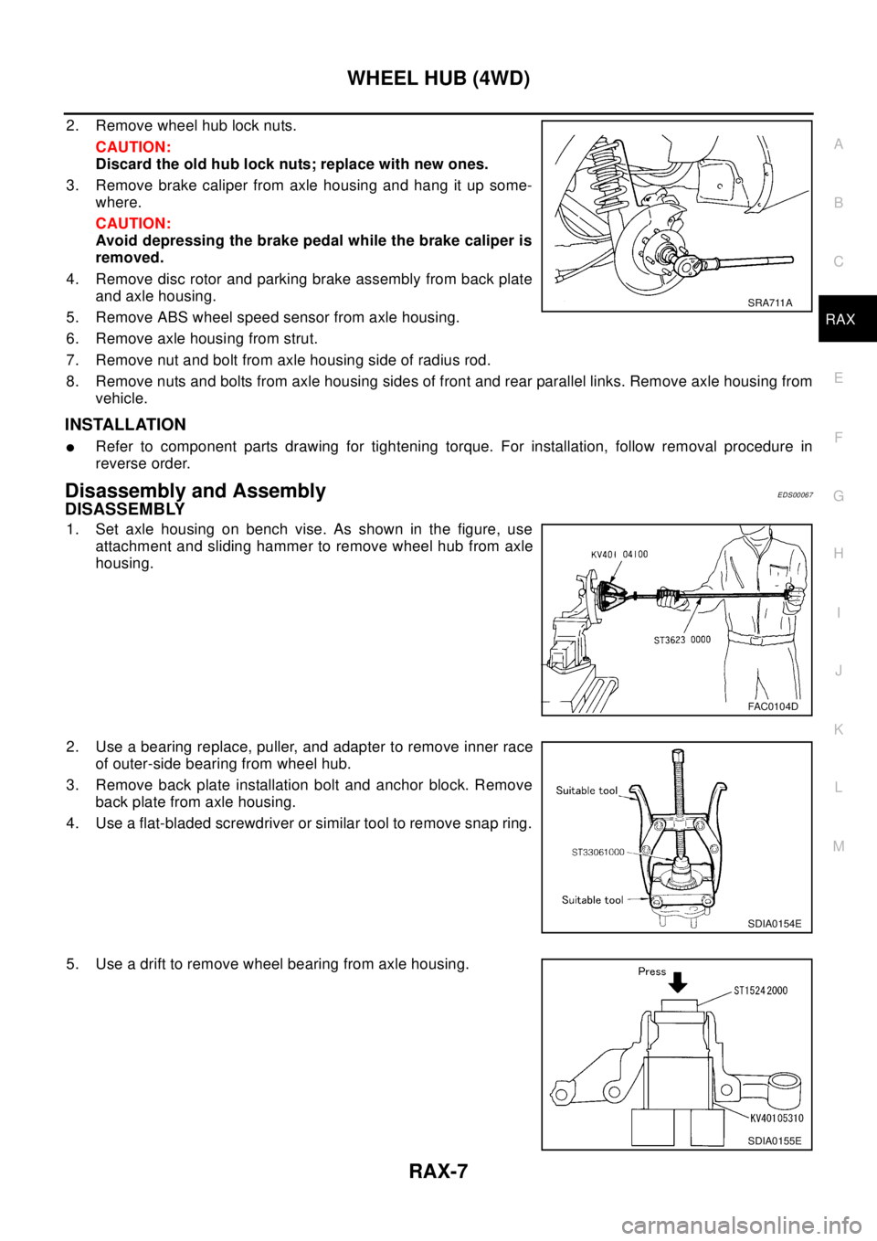
2. Remove wheel hub lock nuts.
CAUTION:
Discard the old hub lock nuts; replace with new ones.
3. Remove brake caliper from axle housing and hang it up some-
where.
CAUTION:
Avoid depressing the brake pedal while the brake caliper is
removed.
4. Remove disc rotor and parking brake assembly from back plate
andaxlehousing.
5. Remove ABS wheel speed sensor from axle housing.
6. Remove axle housing from strut.
7. Remove nut and bolt from axle housing side of radius rod.
8. Remove nuts and bolts from axle housing sides of front and rear parallel links. Remove axle housing from
vehicle.
INSTALLATION
lRefer to component parts drawing for tightening torque. For installation, follow removal procedure in
reverse order.
Disassembly and AssemblyEDS00067
DISASSEMBLY
1. Set axle housing on bench vise. As shown in the figure, use
attachment and sliding hammer to remove wheel hub from axle
housing.
2. Use a bearing replace, puller, and adapter to remove inner race
of outer-side bearing from wheel hub.
3. Remove back plate installation bolt and anchor block. Remove
back plate from axle housing.
4. Use a flat-bladed screwdriver or similar tool to remove snap ring.
5. Use a drift to remove wheel bearing from axle housing.
SRA711A
FAC0104D
SDIA0154E
SDIA0155E
Page 2804 of 3066
RAX-8
WHEEL HUB (4WD)
INSPECTION AFTER DISASSEMBLY
Wheel Hub
lInspect wheel hub for deformation, cracks, and other damage. If any irregular conditions are found,
replace wheel hub.
Axle Housing
lInspect axle housing for deformation, cracks, and other damage. If any irregular conditions are found,
replace axle housing.
Snap Ring
lCheck snap ring for deformation, cracks, and other damage. If any irregular conditions are found, replace
snap ring.
ASSEMBLY
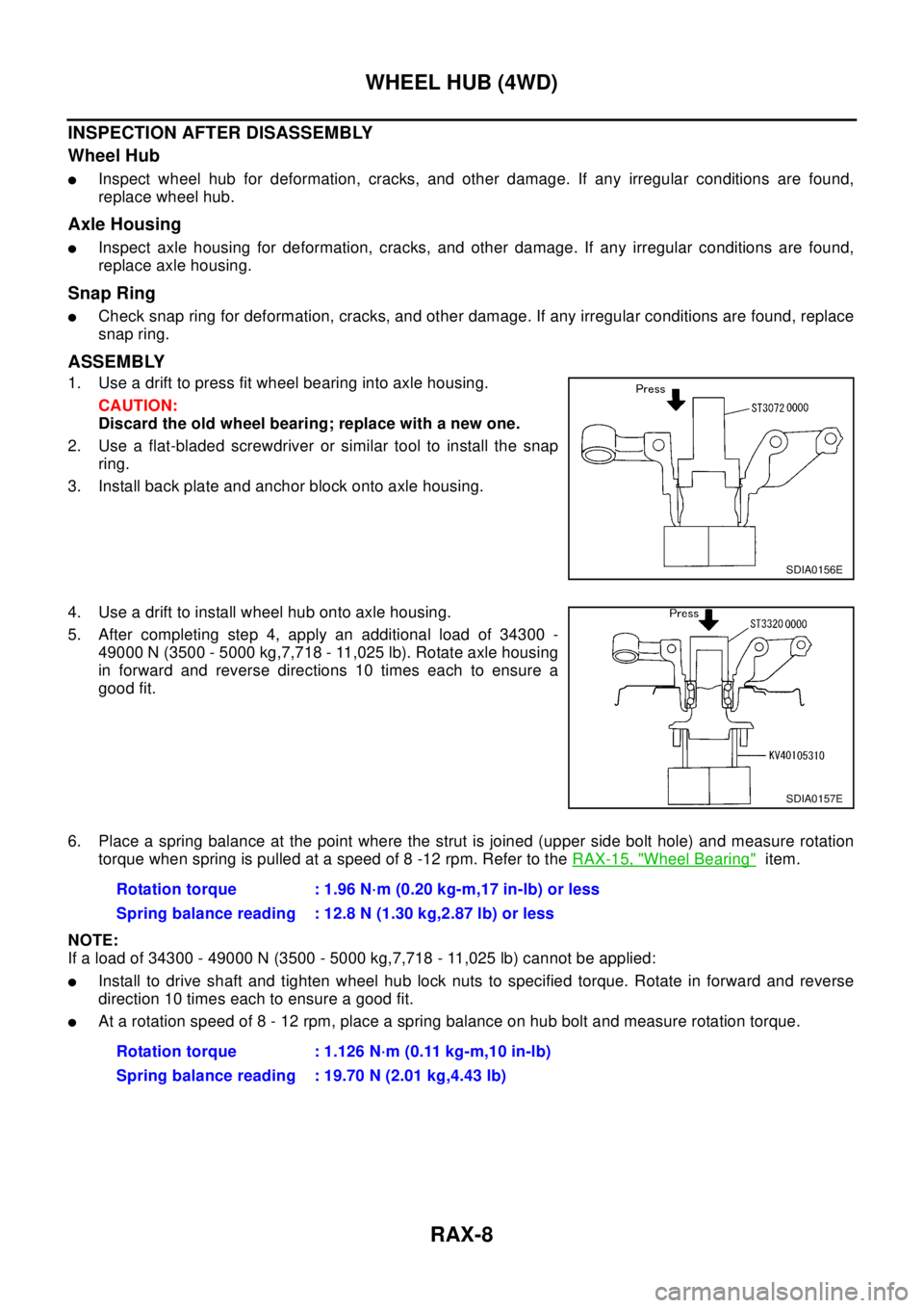
1. Use a drift to press fit wheel bearing into axle housing.
CAUTION:
Discard the old wheel bearing; replace with a new one.
2. Use a flat-bladed screwdriver or similar tool to install the snap
ring.
3. Install back plate and anchor block onto axle housing.
4. Use a drift to install wheel hub onto axle housing.
5. After completing step 4, apply an additional load of 34300 -
49000 N (3500 - 5000 kg,7,718 - 11,025 lb). Rotate axle housing
in forward and reverse directions 10 times each to ensure a
good fit.
6. Place a spring balance at the point where the strut is joined (upper side bolt hole) and measure rotation
torque when spring is pulled at a speed of 8 -12 rpm. Refer to theRAX-15, "
Wheel Bearing"item.
NOTE:
If a load of 34300 - 49000 N (3500 - 5000 kg,7,718 - 11,025 lb) cannot be applied:
lInstall to drive shaft and tighten wheel hub lock nuts to specified torque. Rotate in forward and reverse
direction 10 times each to ensure a good fit.
lAt a rotation speed of 8 - 12 rpm, place a spring balance on hub bolt and measure rotation torque.
SDIA0156E
SDIA0157E
Rotation torque : 1.96 N·m (0.20 kg-m,17 in-lb) or less
Spring balance reading : 12.8 N (1.30 kg,2.87 lb) or less
Rotation torque : 1.126 N·m (0.11 kg-m,10 in-lb)
Spring balance reading : 19.70 N (2.01 kg,4.43 lb)