4WD NISSAN X-TRAIL 2003 Electronic Manual PDF
[x] Cancel search | Manufacturer: NISSAN, Model Year: 2003, Model line: X-TRAIL, Model: NISSAN X-TRAIL 2003Pages: 3066, PDF Size: 51.47 MB
Page 1353 of 3066
![NISSAN X-TRAIL 2003 Electronic Manual PDF DTC P0500 VSS
EC-239
[QR (WITH EURO-OBD)]
C
D
E
F
G
H
I
J
K
L
MA
EC
DTC P0500 VSSPFP:32702
Component DescriptionEBS00B6N
The vehicle speed signal is sent to the combination meter from the ESP/TCS/ABS](/img/5/57402/w960_57402-1352.png "NISSAN X-TRAIL 2003 Electronic Manual PDF DTC P0500 VSS
EC-239
[QR (WITH EURO-OBD)]
C
D
E
F
G
H
I
J
K
L
MA
EC
DTC P0500 VSSPFP:32702
Component DescriptionEBS00B6N
The vehicle speed signal is sent to the combination meter from the ESP/TCS/ABS")
DTC P0500 VSS
EC-239
[QR (WITH EURO-OBD)]
C
D
E
F
G
H
I
J
K
L
MA
EC
DTC P0500 VSSPFP:32702
Component DescriptionEBS00B6N
The vehicle speed signal is sent to the combination meter from the ESP/TCS/ABS control unit (with ESP mod-
els), 4WD/ABS control unit (without ESP models). The combination meter then sends a signal to the ECM.
ECM Terminals and Reference ValueEBS00B6O
Specification data are reference values and are measured between each terminal and body ground.
CAUTION:
Do not use ECM ground terminals when measuring input/output voltage. Doing so may result in dam-
age to the ECM's transistor. Use a ground other than ECM terminals, such as the ground.
: Average voltage for pulse signal (Actual pulse signal can be confirmed by oscilloscope.)
On Board Diagnosis LogicEBS00B6P
DTC Confirmation ProcedureEBS00B6Q
CAUTION:
Always drive vehicle at a safe speed.
NOTE:
If “DTC Confirmation Procedure” has been previously conducted, always turn ignition switch “OFF” and wait at
least 10 seconds before conducting the next test.
TESTING CONDITION:
This procedure may be conducted with the drive wheels lifted in the shop or by driving the vehicle. If a
road test is expected to be easier, it is unnecessary to lift the vehicle.
WITH CONSULT-II
1. Start engine.
TER-
MINAL
NO.WIRE
COLORITEM CONDITION DATA (DC Voltage)
81 L/B Vehicle speed sensor[Engineisrunning]
lLift up the vehicle
lVehicle speed is 40 km/h (25MPH)Approximately 2.3V
PBIB0531E
DTC No. Trouble diagnosis name DTC detecting condition Possible cause
P0500
0500Vehicle speed sensorThe almost 0 km/h (0 MPH) signal from
combination meter is sent to ECM even
when vehicle is being driven.
lHarness or connectors
(The sensor circuit is open or shorted)
lWheel sensor
lESP/TCS/ABS control unit (with ESP models)
l4WD/ABS control unit (without ESP models)
lCombination meter
Page 1357 of 3066
![NISSAN X-TRAIL 2003 Electronic Manual PDF DTC P0500 VSS
EC-243
[QR (WITH EURO-OBD)]
C
D
E
F
G
H
I
J
K
L
MA
EC
Diagnostic ProcedureEBS00B6T
1.CHECK DTC WITH ESP/TCS/ABS CONTROL UNIT, 4WD/ABS CONTROL UNIT
Check DTC with ESP/TCS/ABS control unit](/img/5/57402/w960_57402-1356.png "NISSAN X-TRAIL 2003 Electronic Manual PDF DTC P0500 VSS
EC-243
[QR (WITH EURO-OBD)]
C
D
E
F
G
H
I
J
K
L
MA
EC
Diagnostic ProcedureEBS00B6T
1.CHECK DTC WITH ESP/TCS/ABS CONTROL UNIT, 4WD/ABS CONTROL UNIT
Check DTC with ESP/TCS/ABS control unit")
DTC P0500 VSS
EC-243
[QR (WITH EURO-OBD)]
C
D
E
F
G
H
I
J
K
L
MA
EC
Diagnostic ProcedureEBS00B6T
1.CHECK DTC WITH ESP/TCS/ABS CONTROL UNIT, 4WD/ABS CONTROL UNIT
Check DTC with ESP/TCS/ABS control unit (with ESP models), 4WD/ABS control unit (without ESP models).
Refer toBRC-60
orBRC-7.
OK or NG
OK >> GO TO 2.
NG >> Perform trouble shooting relevant to DTC indicated.
2.CHECK COMBINATION METER
Check combination meter function.
Refer toDI-10, "
Meter/Gauge Operation and Odo/Trip Meter Segment Check in Diagnosis Mode"(LHD mod-
els),DI-28, "
Meter/Gauge Operation and Odo/Trip Meter Segment Check in Diagnosis Mode"(RHD models).
OK or NG
OK >> GO TO 3.
NG >> Perform trouble shooting relevant to combination meter.
3.CHECK INPUT SIGNAL CIRCUIT
1. Turn ignition switch "OFF".
2. Disconnect ECM harness connector and combination meter harness connector.
3. Check harness continuity between ECM terminal 81 and combination meter terminal 49 (LHD models), 62
(RHD models).
Refer to wiring diagram.
4. Also check harness for short to ground and short to power.
OK or NG
OK >> GO TO 5.
NG >> GO TO 4.
4.DETECT MALFUNCTIONING PART
Check the following.
lHarness connectors M62, F42
lHarness for open or short between ECM and combination meter
>> Repair harness or connectors.
5.CHECK INTERMITTENT INCIDENT
PerformEC-107, "
TROUBLE DIAGNOSIS FOR INTERMITTENT INCIDENT".
>>INSPECTION END Continuity should exist.
Page 1508 of 3066
![NISSAN X-TRAIL 2003 Electronic Manual PDF EC-394
[QR (WITHOUT EURO-OBD)]
ENGINE CONTROL SYSTEM
FOR M/T MODELS
System Diagram
Input/Output Signal Chart
T: Transmit R: Receive Accelerator pedal position signal T R
A/T self-diagnosis signal R TS](/img/5/57402/w960_57402-1507.png "NISSAN X-TRAIL 2003 Electronic Manual PDF EC-394
[QR (WITHOUT EURO-OBD)]
ENGINE CONTROL SYSTEM
FOR M/T MODELS
System Diagram
Input/Output Signal Chart
T: Transmit R: Receive Accelerator pedal position signal T R
A/T self-diagnosis signal R TS")
EC-394
[QR (WITHOUT EURO-OBD)]
ENGINE CONTROL SYSTEM
FOR M/T MODELS
System Diagram
Input/Output Signal Chart
T: Transmit R: Receive Accelerator pedal position signal T R
A/T self-diagnosis signal R TSignals ECM TCM
SKIA0885E
Signals ECMSteering wheel
angle sensor4WD control unitESP/ TCS / ABS
control unit
Engine speed signal T R R
Accelerator pedal position signal T R
ESP operation signal R R T
TCS operation signal R R T
ABS operation signal R R T
Stop lamp switch signalRT
Steering wheel angle sensor signal T R
ESP-OFFSW signalRT
Wheel speed sensor signalRT
4WD Mode signalTR
Page 1627 of 3066
![NISSAN X-TRAIL 2003 Electronic Manual PDF DTC P0500 VSS
EC-513
[QR (WITHOUT EURO-OBD)]
C
D
E
F
G
H
I
J
K
L
MA
EC
DTC P0500 VSSPFP:32702
Component DescriptionEBS00BHY
The vehicle speed signal is sent to the combination meter from the ESP/TCS/A](/img/5/57402/w960_57402-1626.png "NISSAN X-TRAIL 2003 Electronic Manual PDF DTC P0500 VSS
EC-513
[QR (WITHOUT EURO-OBD)]
C
D
E
F
G
H
I
J
K
L
MA
EC
DTC P0500 VSSPFP:32702
Component DescriptionEBS00BHY
The vehicle speed signal is sent to the combination meter from the ESP/TCS/A")
DTC P0500 VSS
EC-513
[QR (WITHOUT EURO-OBD)]
C
D
E
F
G
H
I
J
K
L
MA
EC
DTC P0500 VSSPFP:32702
Component DescriptionEBS00BHY
The vehicle speed signal is sent to the combination meter from the ESP/TCS/ABS control unit (with ESP mod-
els), 4WD/ABS control unit (without ESP models). The combination meter then sends a signal to the ECM.
ECM Terminals and Reference ValueEBS00BHZ
Specification data are reference values and are measured between each terminal and body ground.
CAUTION:
Do not use ECM ground terminals when measuring input/output voltage. Doing so may result in dam-
age to the ECM's transistor. Use a ground other than ECM terminals, such as the ground.
: Average voltage for pulse signal (Actual pulse signal can be confirmed by oscilloscope.)
On Board Diagnosis LogicEBS00BI0
DTC Confirmation ProcedureEBS00BI1
CAUTION:
Always drive vehicle at a safe speed.
NOTE:
If “DTC Confirmation Procedure” has been previously conducted, always turn ignition switch “OFF” and wait at
least 10 seconds before conducting the next test.
TESTING CONDITION:
This procedure may be conducted with the drive wheels lifted in the shop or by driving the vehicle. If a
road test is expected to be easier, it is unnecessary to lift the vehicle.
WITH CONSULT-II
1. Start engine.
TER-
MINAL
NO.WIRE
COLORITEM CONDITION DATA (DC Voltage)
81 L/B Vehicle speed sensor[Engineisrunning]
lLift up the vehicle
lVehicle speed is 40 km/h (25MPH)Approximately 2.3V
PBIB0531E
DTC No. Trouble diagnosis name DTC detecting condition Possible cause
P0500
0500Vehicle speed sensorThe almost 0 km/h (0 MPH) signal from
combination meter is sent to ECM even
when vehicle is being driven.
lHarness or connectors
(The sensor circuit is open or shorted)
lWheel sensor
lESP/TCS/ABS control unit (with ESP models)
l4WD/ABS control unit (without ESP models)
lCombination meter
Page 1631 of 3066
![NISSAN X-TRAIL 2003 Electronic Manual PDF DTC P0500 VSS
EC-517
[QR (WITHOUT EURO-OBD)]
C
D
E
F
G
H
I
J
K
L
MA
EC
Diagnostic ProcedureEBS00BI4
1.CHECK DTC WITH ESP/TCS/ABS CONTROL UNIT, 4WD/ABS CONTROL UNIT
Check DTC with ESP/TCS/ABS control u](/img/5/57402/w960_57402-1630.png "NISSAN X-TRAIL 2003 Electronic Manual PDF DTC P0500 VSS
EC-517
[QR (WITHOUT EURO-OBD)]
C
D
E
F
G
H
I
J
K
L
MA
EC
Diagnostic ProcedureEBS00BI4
1.CHECK DTC WITH ESP/TCS/ABS CONTROL UNIT, 4WD/ABS CONTROL UNIT
Check DTC with ESP/TCS/ABS control u")
DTC P0500 VSS
EC-517
[QR (WITHOUT EURO-OBD)]
C
D
E
F
G
H
I
J
K
L
MA
EC
Diagnostic ProcedureEBS00BI4
1.CHECK DTC WITH ESP/TCS/ABS CONTROL UNIT, 4WD/ABS CONTROL UNIT
Check DTC with ESP/TCS/ABS control unit (with ESP models), 4WD/ABS control unit (without ESP models).
Refer toBRC-60
orBRC-7.
OK or NG
OK >> GO TO 2.
NG >> Perform trouble shooting relevant to DTC indicated.
2.CHECK COMBINATION METER
Check combination meter function.
Refer toDI-10, "
Meter/Gauge Operation and Odo/Trip Meter Segment Check in Diagnosis Mode"(LHD mod-
els),DI-28, "
Meter/Gauge Operation and Odo/Trip Meter Segment Check in Diagnosis Mode"(RHD models).
OK or NG
OK >> GO TO 3.
NG >> Perform trouble shooting relevant to combination meter.
3.CHECK INPUT SIGNAL CIRCUIT
1. Turn ignition switch "OFF".
2. Disconnect ECM harness connector and combination meter harness connector.
3. Check harness continuity between ECM terminal 81 and combination meter terminal 49 (LHD models), 62
(RHD models).
Refer to wiring diagram.
4. Also check harness for short to ground and short to power.
OK or NG
OK >> GO TO 5.
NG >> GO TO 4.
4.DETECT MALFUNCTIONING PART
Check the following.
lHarness connectors M62, F42
lHarness for open or short between ECM and combination meter
>> Repair harness or connectors.
5.CHECK INTERMITTENT INCIDENT
PerformEC-453, "
TROUBLE DIAGNOSIS FOR INTERMITTENT INCIDENT".
>>INSPECTION END Continuity should exist.
Page 1858 of 3066
![NISSAN X-TRAIL 2003 Electronic Manual PDF EC-744
[YD]
DTC P0500 VEHICLE SPEED SENSOR (VSS)
DTC P0500 VEHICLE SPEED SENSOR (VSS)
PFP:32702
DescriptionEBS004QL
The vehicle speed signal is sent to the combination meter from the 4WD/ABS control u](/img/5/57402/w960_57402-1857.png "NISSAN X-TRAIL 2003 Electronic Manual PDF EC-744
[YD]
DTC P0500 VEHICLE SPEED SENSOR (VSS)
DTC P0500 VEHICLE SPEED SENSOR (VSS)
PFP:32702
DescriptionEBS004QL
The vehicle speed signal is sent to the combination meter from the 4WD/ABS control u")
EC-744
[YD]
DTC P0500 VEHICLE SPEED SENSOR (VSS)
DTC P0500 VEHICLE SPEED SENSOR (VSS)
PFP:32702
DescriptionEBS004QL
The vehicle speed signal is sent to the combination meter from the 4WD/ABS control unit. The combination
meter then sends a signal to the ECM.
ECM Terminals and Reference ValueEBS004QM
Specification data are reference values and are measured between each terminal and ground.
CAUTION:
Do not use ECM ground terminals when measuring input/output voltage. Doing so may result in dam-
age to the ECM's transistor. Use a ground other than ECM terminals, such as the ground.
: Average voltage for pulse signal (Actual pulse signal can be confirmed by oscilloscope.)
On Board Diagnosis LogicEBS004QN
Overall Function CheckEBS004QO
Use this procedure to check the overall function of the vehicle speed sensor circuit. During this check, a DTC
might not be confirmed.
WITH CONSULT-II
1. Lift up the vehicle.
2. Start engine.
3. Read vehicle speed sensor signal by oscilloscope under the fol-
lowing conditions.
lIn 2nd gear position.
lVehicle speed is 30km/h (19MPH)
The oscilloscope should indicate the almost same signal
wave as that shown in the "ECM Terminals and Reference
Value".
4. If NG, go toEC-747, "
Diagnostic Procedure".
TER-
MINAL
NO.WIRE
COLORITEM CONDITIONDATA
(DC Voltage and Pulse Signal)
E21 L/B Vehicle speed sensor[Engine is running]
lLift up the vehicle
lIn 2nd gear position
lVehicle speed is 30 km/h (19 MPH)0-5V
PBIB0386E
DTC Malfunction is detected when .... Check Items (Possible Cause)
P0500
lThe almost 0 km/h (0 MPH) signal from vehicle
speed sensor is sent to ECM even when vehicle is
being driven.
lAn excessively high voltage from the sensor is send
to ECM
lHarness or connectors
(The sensor circuit is open or shorted.)
lVehicle speed sensor
lCombination meter
l4WD/ABS control unit
SEF864Y
Page 1861 of 3066
![NISSAN X-TRAIL 2003 Electronic Manual PDF DTC P0500 VEHICLE SPEED SENSOR (VSS)
EC-747
[YD]
C
D
E
F
G
H
I
J
K
L
MA
EC
Diagnostic ProcedureEBS004QQ
1.CHECK DTC WITH 4WD/ABS CONTROL UNIT
Check DTC with 4WD/ABS control unit.
Refer toBRC-7, "
TROU](/img/5/57402/w960_57402-1860.png "NISSAN X-TRAIL 2003 Electronic Manual PDF DTC P0500 VEHICLE SPEED SENSOR (VSS)
EC-747
[YD]
C
D
E
F
G
H
I
J
K
L
MA
EC
Diagnostic ProcedureEBS004QQ
1.CHECK DTC WITH 4WD/ABS CONTROL UNIT
Check DTC with 4WD/ABS control unit.
Refer toBRC-7, \"
TROU")
DTC P0500 VEHICLE SPEED SENSOR (VSS)
EC-747
[YD]
C
D
E
F
G
H
I
J
K
L
MA
EC
Diagnostic ProcedureEBS004QQ
1.CHECK DTC WITH 4WD/ABS CONTROL UNIT
Check DTC with 4WD/ABS control unit.
Refer toBRC-7, "
TROUBLE DIAGNOSIS".
OK or NG
OK >> GO TO 2.
NG >> Reform trouble shooting relevant to DTC indicated.
2.CHECK SPEEDOMETER FUNCTION
Make sure that speed meter functions properly.
OK or NG
OK >> GO TO 3.
NG >> GO TO 5.
3.CHECK ECM INPUT SIGNAL CIRCUIT FOR OPEN AND SHORT
1. Turn ignition switch "OFF".
2. Disconnect ECM harness connector and combination meter harness connector.
3. Check harness continuity between ECM terminal E21 and combination meter terminal 50 or 63. Refer to
Wiring Diagram.
4. Also check harness for short to ground or short to power.
OK or NG
OK >> GO TO 8.
NG >> GO TO 4.
4.DETECT MALFUNCTIONING PART
Check the following.
lHarness connectors M64, F29
lHarness for open and short between ECM and combination meter
>> Repair open circuit or short to ground or short to power in harness or connectors.
5.CHECK SPEEDOMATER INPUT SIGNL FOR OPEN AND SHORT
1. Turn ignition switch "OFF".
2. Disconnect combination meter harness connector and 4WD/ABS control unit harness connector.
3. Check continuity between combination meter terminal 52 or 42 and 4WD/ABS control unit harness con-
nector. Refer to Wiring Diagram.
4. Also check harness for short to ground and short to power.
OK or NG
OK >> GO TO 7.
NG >> GO TO 6.Continuity should exist.
Continuity should exist.
Page 1862 of 3066
![NISSAN X-TRAIL 2003 Electronic Manual PDF EC-748
[YD]
DTC P0500 VEHICLE SPEED SENSOR (VSS)
6.DETECT MALFUNCTIONING PART
Check the following.
lHarness connectors M14, E106
lHarness for open and short between 4WD/ABS control unit and combinatio](/img/5/57402/w960_57402-1861.png "NISSAN X-TRAIL 2003 Electronic Manual PDF EC-748
[YD]
DTC P0500 VEHICLE SPEED SENSOR (VSS)
6.DETECT MALFUNCTIONING PART
Check the following.
lHarness connectors M14, E106
lHarness for open and short between 4WD/ABS control unit and combinatio")
EC-748
[YD]
DTC P0500 VEHICLE SPEED SENSOR (VSS)
6.DETECT MALFUNCTIONING PART
Check the following.
lHarness connectors M14, E106
lHarness for open and short between 4WD/ABS control unit and combination meter
>> Repair open circuit or short to ground or short to power in harness or connectors.
7.CHECK SPEED METER
Refer toDI-4, "
COMBINATION METERS (LHD MODELS)"orDI-22, "COMBINATION METERS (RHD MOD-
ELS)".
OK or NG
OK >> GO TO 8.
NG >> Replace combination meter.
8.CHECK INTERMITTENT INCIDENT
Refer toEC-699, "
TROUBLE DIAGNOSIS FOR INTERMITTENT INCIDENT".
>>INSPECTION END
Page 2213 of 3066
SERVICE DATA AND SPECIFICATIONS (SDS)
FAX-17
C
E
F
G
H
I
J
K
L
MA
B
FA X
SERVICE DATA AND SPECIFICATIONS (SDS)PFP:00030
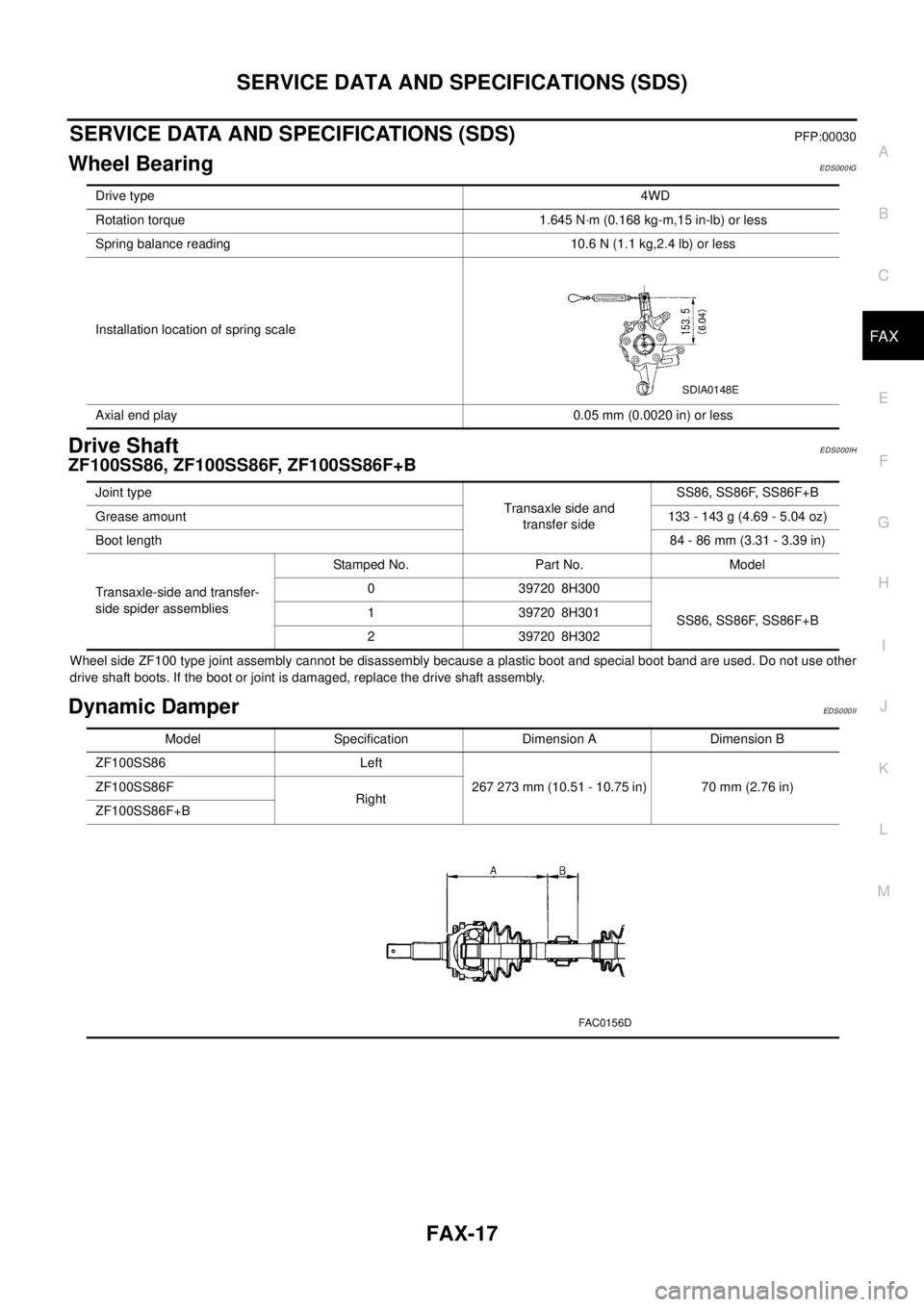
Wheel BearingEDS000IG
Drive ShaftEDS000IH
ZF100SS86, ZF100SS86F, ZF100SS86F+B
Wheel side ZF100 type joint assembly cannot be disassembly because a plastic boot and special boot band are used. Do not use other
drive shaft boots. If the boot or joint is damaged, replace the drive shaft assembly.
Dynamic DamperEDS0 00 II
Drive type4WD
Rotation torque 1.645 N·m (0.168 kg-m,15 in-lb) or less
Spring balance reading 10.6 N (1.1 kg,2.4 lb) or less
Installation location of spring scale
Axial end play 0.05 mm (0.0020 in) or less
SDIA0148E
Joint type
Transaxle side and
transfer sideSS86, SS86F, SS86F+B
Grease amount133-143g(4.69-5.04oz)
Boot length84 - 86 mm (3.31 - 3.39 in)
Transaxle-side and transfer-
side spider assembliesStamped No. Part No. Model
0 39720 8H300
SS86, SS86F, SS86F+B 1 39720 8H301
2 39720 8H302
Model Specification Dimension A Dimension B
ZF100SS86 Left
267 273 mm (10.51 - 10.75 in) 70 mm (2.76 in) ZF100SS86F
Right
ZF100SS86F+B
FAC0156D
Page 2252 of 3066
SERVICE DATA AND SPECIFICATIONS (SDS)
FSU-13
C
D
F
G
H
I
J
K
L
MA
B
FSU
SERVICE DATA AND SPECIFICATIONS (SDS)PFP:00030
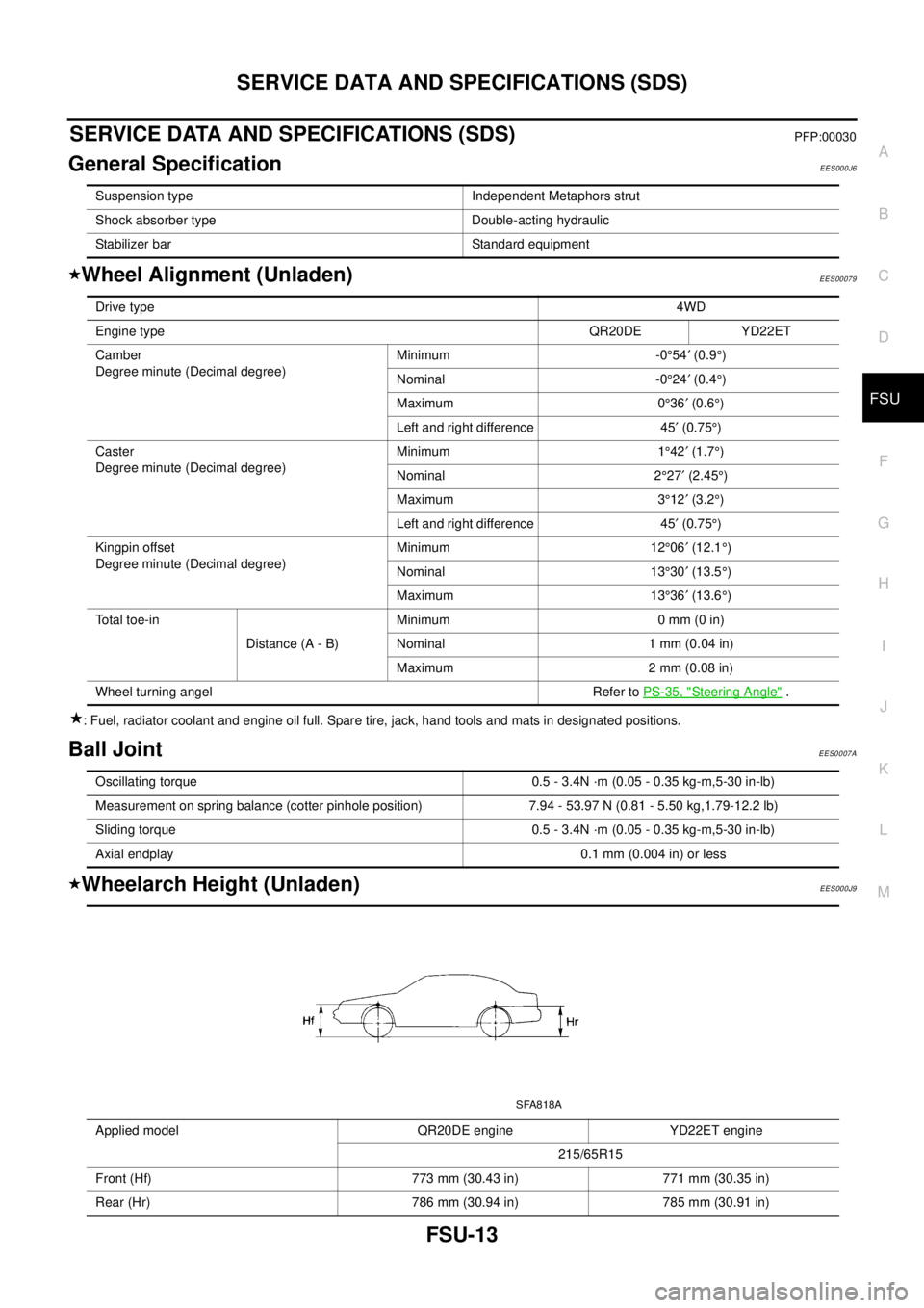
General SpecificationEES000J6
Wheel Alignment (Unladen)EES00079
: Fuel, radiator coolant and engine oil full. Spare tire, jack, hand tools and mats in designated positions.
Ball JointEES0007A
Wheelarch Height (Unladen)EES000J9
Suspension type Independent Metaphors strut
Shock absorber type Double-acting hydraulic
Stabilizer bar Standard equipment
Drive type4WD
Engine typeQR20DE YD22ET
Camber
Degree minute (Decimal degree)Minimum -0°54¢(0.9°)
Nominal -0°24¢(0.4°)
Maximum 0°36¢(0.6°)
Left and right difference 45¢(0.75°)
Caster
Degree minute (Decimal degree)Minimum 1°42¢(1.7°)
Nominal 2°27¢(2.45°)
Maximum 3°12¢(3.2°)
Left and right difference 45¢(0.75°)
Kingpin offset
Degree minute (Decimal degree)Minimum 12°06¢(12.1°)
Nominal 13°30¢(13.5°)
Maximum 13°36¢(13.6°)
To t a l t o e - i n
Distance (A - B)Minimum 0 mm (0 in)
Nominal 1 mm (0.04 in)
Maximum 2 mm (0.08 in)
Wheel turning angel Refer toPS-35, "
Steering Angle".
Oscillating torque 0.5 - 3.4N ·m (0.05 - 0.35 kg-m,5-30 in-lb)
Measurement on spring balance (cotter pinhole position) 7.94 - 53.97 N (0.81 - 5.50 kg,1.79-12.2 lb)
Sliding torque 0.5 - 3.4N ·m (0.05 - 0.35 kg-m,5-30 in-lb)
Axial endplay 0.1 mm (0.004 in) or less
Applied model QR20DE engine YD22ET engine
215/65R15
Front (Hf) 773 mm (30.43 in) 771 mm (30.35 in)
Rear (Hr) 786 mm (30.94 in) 785 mm (30.91 in)
SFA818A