check engine NISSAN X-TRAIL 2003 Electronic Repair Manual
[x] Cancel search | Manufacturer: NISSAN, Model Year: 2003, Model line: X-TRAIL, Model: NISSAN X-TRAIL 2003Pages: 3066, PDF Size: 51.47 MB
Page 3016 of 3066

TF-46
TROUBLE DIAGNOSIS
CAUTION:
If memory cannot be erased, proceed to 5.
9. Drive at approx. 30 km/h (19MPH) for approx. 1 minute. Be sure 4WD warning lamp is OFF.
Display item list
CAUTION:
lIf "ALL MODE 4WD" is not displayed on system selection screen, check the following: 4WD actua-
tor and control unit, data link connector harness, and No. of CONSULT-II program card
lWhen several systems including CAN communication system indicates troubles, perform trouble
diagnosis of the CAN communication primarily.
DATA MONITOR
lFor details of data monitor function, refer to CONSULT -II Operation Manual.
Operation procedure
1. Turn the ignition switch to OFF.
2. Connect CONSULT-II connector to data link connector on vehicle.
3. Turn ignition switch ON.
4. Touch "START" on the display.
5. Touch "ALL MODE 4WD" on the display.
CAUTION:
"ALL MODE 4WD" may not be displayed on the system selection screen in the following case:
When "START" was touched just after engine is started or ignition switch is turned to ON. In this
case, repeat procedure from step 2.
6. Touch "DATA MONITOR".
7. Return to monitor item selection screen. Touch any of "ECU INPUT SIGNALS," "MAIN SIGNALS," "CAN
DIG SUPPORT MNTR" or "SELECTION FROM MENU".
Refer to the following "Data monitor item chart".
Item Malfunction detecting condition Check harness
DECEL G-SENSOR Longitudinal G-sensor output voltage is outside specification.
G-sensor harness
G-SENSOR VOLTAGEPower voltage of longitudinal G-sensor remains abnormally high
or low for a certain period of time.
ETS SOLENOID
(4WD solenoid valve) (Open)4WD solenoid valve control terminal is not supplied with proper
voltage due to open circuit in 4WD solenoid valve.
4WD actuator relay,
solenoid and harness ETS SOLENOID
(4WD solenoid valve) (Short)4WD solenoid valve control terminal is not supplied with proper
voltage due to short circuit in 4WD solenoid valve.
ETS SOLENOID
(4WD solenoid valve)
(CURRENT FAILURE)Current supplied to 4WD solenoid valve is abnormally high or
low compared with the specification.
CONTROL UNIT Processing function of 4WD control unit is malfunctioning.4WD control unit, power
and ground circuits
DECEL G-SEN MONI Output voltage of longitudinal G-sensor is outside specification. G-sensor harness
DECEL G-SEN IN Input voltage of longitudinal G-sensor is outside specification. G-sensor harness
3 V POWER SUPLY CHECK 4WD control unit internal 3V power supply is malfunctioning.Control unit power sup-
ply circuit
4WD A/R CHECK 4WD actuator relay turned on while it is controlled OFF.
4WD actuator relay,
4WD solenoid and har-
ness. 4WD SOL/V CHECK4WD solenoid not supplied with proper voltage
due to open circuit in 4WD solenoid valve.
CAN COMM
lCAN communication function of 4WD control unit is malfunc-
tioning.
lCAN communication function of EPS control unit is malfunc-
tioning.Control unit power sup-
ply circuit
ABS 4WD COMMWheel speed sensor system of ESP/TCS/ABS control unit is
malfunctioning.ESP/TCS/ABS control
unit and harness
Page 3019 of 3066

TROUBLE DIAGNOSIS
TF-49
C
E
F
G
H
I
J
K
L
MA
B
TF
4WD solenoid valve
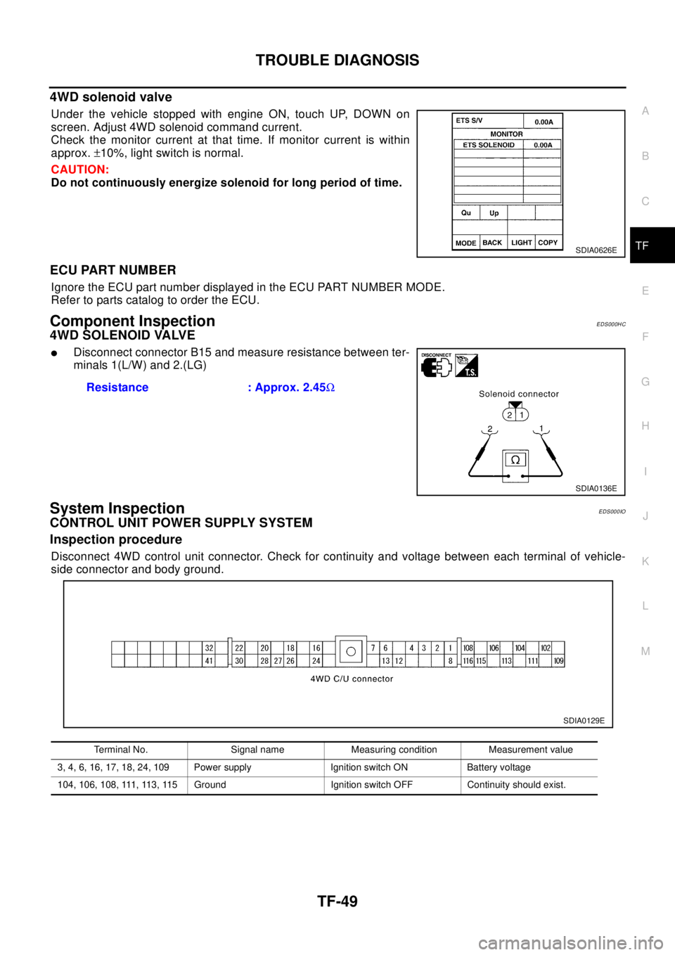
Under the vehicle stopped with engine ON, touch UP, DOWN on
screen. Adjust 4WD solenoid command current.
Check the monitor current at that time. If monitor current is within
approx.±10%, light switch is normal.
CAUTION:
Do not continuously energize solenoid for long period of time.
ECU PART NUMBER
Ignore the ECU part number displayed in the ECU PART NUMBER MODE.
Refer to parts catalog to order the ECU.
Component InspectionEDS000HC
4WD SOLENOID VALVE
lDisconnect connector B15 and measure resistance between ter-
minals 1(L/W) and 2.(LG)
System InspectionEDS000IO
CONTROL UNIT POWER SUPPLY SYSTEM
Inspection procedure
Disconnect 4WD control unit connector. Check for continuity and voltage between each terminal of vehicle-
side connector and body ground.
SDIA0626E
Resistance : Approx. 2.45W
SDIA0136E
Terminal No. Signal name Measuring condition Measurement value
3, 4, 6, 16, 17, 18, 24, 109 Power supply Ignition switch ON Battery voltage
104, 106, 108, 111, 113, 115 Ground Ignition switch OFF Continuity should exist.
SDIA0129E
Page 3025 of 3066

TROUBLE DIAGNOSIS
TF-55
C
E
F
G
H
I
J
K
L
MA
B
TF
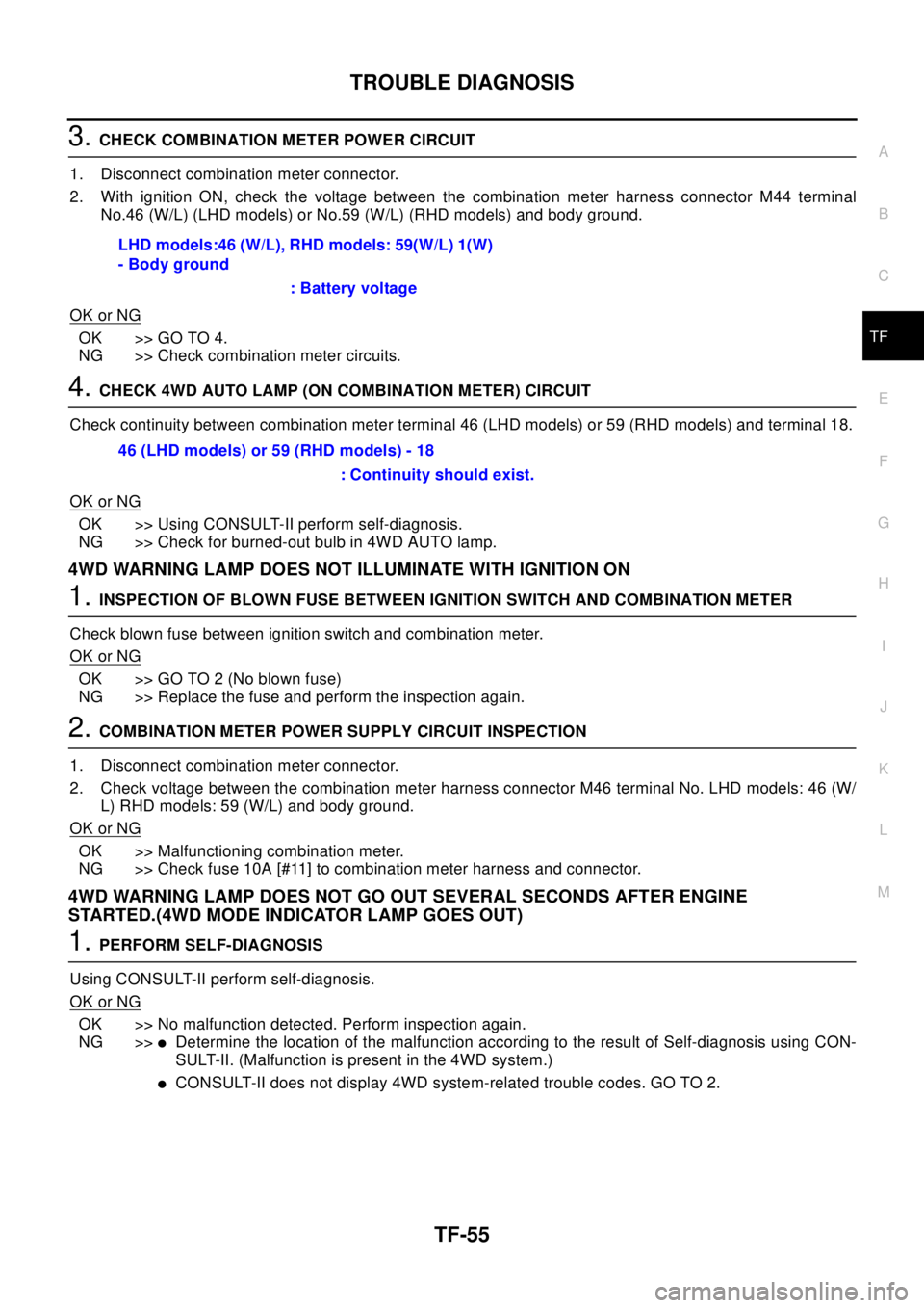
3.CHECK COMBINATION METER POWER CIRCUIT
1. Disconnect combination meter connector.
2. With ignition ON, check the voltage between the combination meter harness connector M44 terminal
No.46 (W/L) (LHD models) or No.59 (W/L) (RHD models) and body ground.
OK or NG
OK >> GO TO 4.
NG >> Check combination meter circuits.
4.CHECK 4WD AUTO LAMP (ON COMBINATION METER) CIRCUIT
Check continuity between combination meter terminal 46 (LHD models) or 59 (RHD models) and terminal 18.
OK or NG
OK >> Using CONSULT-II perform self-diagnosis.
NG >> Check for burned-out bulb in 4WD AUTO lamp.
4WD WARNING LAMP DOES NOT ILLUMINATE WITH IGNITION ON
1.INSPECTION OF BLOWN FUSE BETWEEN IGNITION SWITCH AND COMBINATION METER
Check blown fuse between ignition switch and combination meter.
OK or NG
OK >> GO TO 2 (No blown fuse)
NG >> Replace the fuse and perform the inspection again.
2.COMBINATION METER POWER SUPPLY CIRCUIT INSPECTION
1. Disconnect combination meter connector.
2. Check voltage between the combination meter harness connector M46 terminal No. LHD models: 46 (W/
L) RHD models: 59 (W/L) and body ground.
OK or NG
OK >> Malfunctioning combination meter.
NG >> Check fuse 10A [#11] to combination meter harness and connector.
4WD WARNING LAMP DOES NOT GO OUT SEVERAL SECONDS AFTER ENGINE
STARTED.(4WD MODE INDICATOR LAMP GOES OUT)
1.PERFORM SELF-DIAGNOSIS
Using CONSULT-II perform self-diagnosis.
OK or NG
OK >> No malfunction detected. Perform inspection again.
NG >>
lDetermine the location of the malfunction according to the result of Self-diagnosis using CON-
SULT-II. (Malfunction is present in the 4WD system.)
lCONSULT-II does not display 4WD system-related trouble codes. GO TO 2. LHD models:46 (W/L), RHD models: 59(W/L) 1(W)
- Body ground
: Battery voltage
46 (LHD models) or 59 (RHD models) - 18
: Continuity should exist.
Page 3026 of 3066

TF-56
TROUBLE DIAGNOSIS
2.4WD CONTROL UNIT CONNECTOR CONNECTION INSPECTION
lCheck 4WD control unit connector for proper connection.
OK or NG
OK >> Reconnect the 4WD control unit connector properly and perform inspection again.
NG >> Repair or replace the connector.
HEAVY TIGHT-CORNER BRAKING SYMPTOM OCCURS WHEN THE VEHICLE IS DRIVEN IN
AUTO MODE AND THE STEERING WHEEL IS TURNED FULLY TO EITHER SIDE AFTER THE
ENGINE IS STARTED
1.PERFORM SELF-DIAGNOSIS.
Using CONSULT-II perform self-diagnosis.
OK or NG
OK >> GO TO 2. (No self-diagnosis malfunction indicated.)
NG >> Determine the location of the malfunction according to the result of self-diagnosis using CON-
SULT-II. (Malfunction is present in the 4WD system.)
2.CHECK USING THE DATA MONITOR FUNCTION OF THE CONSULT- II.
lPerform inspection by the data monitor function of the CONSULT-II.
lCheck that the operation is in AUTO mode.
lMeasure voltage when the accelerator pedal is not depressed. (Accelerator pedal not depressed: approx.
0.5V or lower)
lMeasure the current supplied to the 4WD solenoid valve. (Accelerator pedal not depressed: approx. 0A)
OK or NG
OK >> GO TO 3. (No self-diagnosis malfunction indicated.)
NG >>
lNot in AUTO mode. GO TO 3.
lVoltage when accelerator pedal is not depressed is higher than approximately 0.5V.
l4WD solenoid valve current when the accelerator pedal is not depressed is other than 0A.
lCountermeasure: Keep the vehicle idling for approximately 15 minutes before checking again.
(Voltage when accelerator pedal is not depressed will be automatically reset to zero during this
period.)
Page 3027 of 3066

TROUBLE DIAGNOSIS
TF-57
C
E
F
G
H
I
J
K
L
MA
B
TF
3.INSPECTION USING 4WD MODE CHANGE-OVER SWITCH
lOn data monitor screen of the CONSULT-II, check 4WD mode switch.
lCheck if the display changes from ## to 2WD mode when the 2WD switch is pressed.
lCheck if the display changes from ## to AUTO mode when the AUTO switch is pressed.
lCheck if the display changes from ## to LOCK mode when the LOCK switch is pressed.
OK or NG
OK >> No malfunction detected.
NG >>
lNot in AUTO mode. (in 2WD or LOCK mode)
Countermeasure: Slightly depress the accelerator pedal and check that the operation mode
changes to LOCK mode.
lCheck circuit between 4WD mode switch harness connector M39 terminal No.1 (BR) and
4WD control unit harness connector E122 terminal No. 27 (BR).
(AUTO mode is not available because a malfunction is present in the 2WD mode harness.)
NOTICE:
Mechanism of 4WD mode change-over
l2WD mode: Operation changes to 2WD mode when 4WD control unit harness connector E122
terminal No. 27 (BR) is shorted to ground.
lAUTO mode: Operation changes to AUTO mode when 4WD control unit harness connector
E122 terminals No. 27 (BR) and No. 26 (L) is shorted to ground.
lLOCK mode: Operation changes to LOCK mode when 4WD control unit harness connector
E122 terminal No. 26 (L) is shorted to ground.
4WD MODES CANNOT BE SWITCHED AFTER ENGINE IS STARTED
1.INSPECTION USING 4WD MODE CHANGE-OVER SWITCH
lDrive modes cannot be switched after the engine is started.
lOn data monitor screen of the CONSULT-II, check 4WD mode switch.
lCheck if the display changes from ## to 2WD mode when the 2WD switch is pressed.
lCheck if the display changes from ## to AUTO mode when the AUTO switch is pressed.
lCheck if the display changes from ## to LOCK mode when the LOCK switch is pressed.
OK or NG
OK >> No malfunction detected.
NG >>
lCONSULT-II display does not change from ## when the 2WD switch is pressed. Check harness
of the 2WD switch.
lCONSULT-II display does not change from ## when the AUTO switch is pressed. Check har-
ness of the 2WD switch and LOCK switch.
lCONSULT-II display does not change from ## when the LOCK switch is pressed. Check har-
ness of the LOCK switch.
lPerform 4WD mode change-over switch inspection.
WHILE DRIVING, 4WD WARNING LAMP FLASHES RAPIDLY. (WHEN IT FLASHERS FOR
APPROX. ONE MINUTE, THEN DOES NOT ILLUMINATE.)
lWhile driving, 4WD warning lamp flashes rapidly. (when it flashes for approx. one minute, then does not
illuminate.)
Rapid flashing: 2 times/second
This phenomenon protects drivetrain parts when a heavy load is applied to the electronically controlled
coupling and multiple disc clutch temperature increases. It is not a malfunction.
When the difference of diameters by or with the front and rear wheel with AUTO mode the shift switch
occasionally changes to LOCK mode automatically. This is not a malfunction.
When the difference of revolution speed between the front and rear wheel with AUTO mode, the shift
switch occasionally changes to LOCK mode automatically. This is not a malfunction.
Page 3028 of 3066

TF-58
TROUBLE DIAGNOSIS
WHILE DRIVING, 4WD WARNING LAMP FLASHES SLOWLY. (WHEN IT CONTINUES TO ILLU-
MINATE UNTIL ENGINE TURNS OFF.)
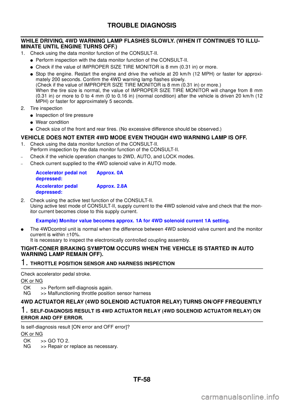
1. Check using the data monitor function of the CONSULT-II.
lPerform inspection with the data monitor function of the CONSULT-II.
lCheck if the value of IMPROPER SIZE TIRE MONITOR is 8 mm (0.31 in) or more.
lStop the engine. Restart the engine and drive the vehicle at 20 km/h (12 MPH) or faster for approxi-
mately 200 seconds. Confirm the 4WD warning lamp flashes slowly.
(Check if the value of IMPROPER SIZE TIRE MONITOR is 8 mm (0.31 in) or more.)
When the tire size is normal, the value of IMPROPER SIZE TIRE MONITOR will change from 8 mm
(0.31 in) or more to 0 to 4 mm (0 to 0.16 in) (normal condition) after the vehicle is driven 20 km/h (12
MPH) or faster for approximately 5 seconds.
2. Tire inspection
lInspection of tire pressure
lWear condition
lCheck size of the front and rear tires. (No excessive difference should be observed.)
VEHICLE DOES NOT ENTER 4WD MODE EVEN THOUGH 4WD WARNING LAMP IS OFF.
1. Check using the data monitor function of the CONSULT-II.
Perform inspection by the data monitor function of the CONSULT-II.
–Check if the vehicle operation changes to 2WD, AUTO, and LOCK modes.
–Check current supplied to the 4WD solenoid valve in AUTO mode.
2. Check using the active test function of the CONSULT-II.
Using active test mode of CONSULT-II, supply current to the 4WD solenoid valve and check that the mon-
itor current becomes close to this supply current.
lThe 4WDcontrol unit is normal when the difference between 4WD solenoid valve current and the monitor
current is within±10%.
It is necessary to inspect the electronically controlled coupling assembly.
TIGHT-CONER BRAKING SYMPTOM OCCURS WHEN THE VEHICLE IS STARTED IN AUTO
WARNING LAMP REMAIN OFF).
1.THROTTLE POSITION SENSOR AND HARNESS INSPECTION
Check accelerator pedal stroke.
OK or NG
OK >> Perform self-diagnosis again.
NG >> Malfunctioning throttle position sensor harness
4WD ACTUATOR RELAY (4WD SOLENOID ACTUATOR RELAY) TURNS ON/OFF FREQUENTLY
1.SELF-DIAGNOSIS RESULT IS 4WD ACTUATOR RELAY (4WD SOLENOID ACTUATOR RELAY) ON
ERROR AND OFF ERROR.
Is self-diagnosis result [ON error and OFF error]?
OK or NG
OK >> GO TO 2.
NG >> Repair or replace as necessary.Accelerator pedal not
depressed:Approx. 0A
Accelerator pedal
depressed:Approx. 2.8A
Example) Monitor value becomes approx. 1A for 4WD solenoid current 1A setting.
Page 3049 of 3066

FRONT WIPER AND WASHER SYSTEM
WW-11
C
D
E
F
G
H
I
J
L
MA
B
WW
Removal and Installation for Washer NozzleEKS0032U
REMOVAL
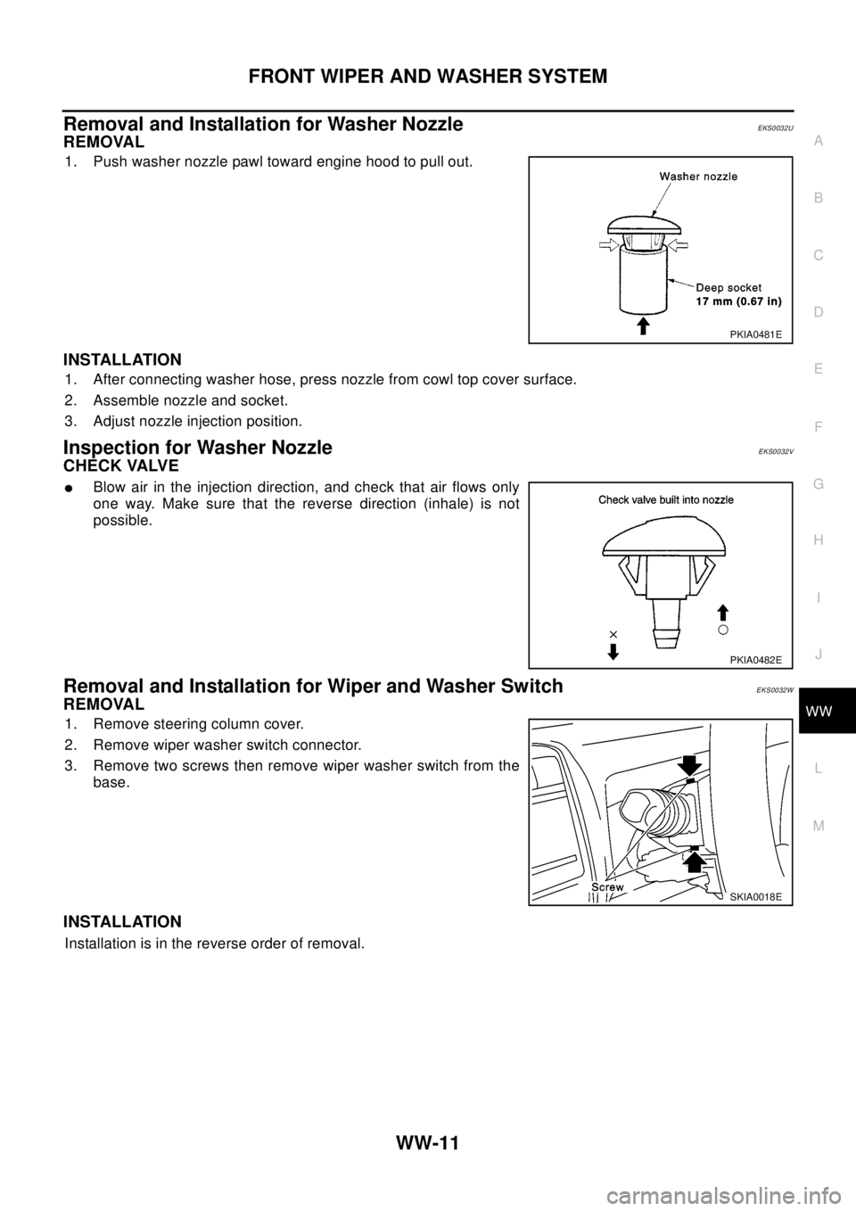
1. Push washer nozzle pawl toward engine hood to pull out.
INSTALLATION
1. After connecting washer hose, press nozzle from cowl top cover surface.
2. Assemble nozzle and socket.
3. Adjust nozzle injection position.
Inspection for Washer NozzleEKS0032V
CHECK VALVE
lBlow air in the injection direction, and check that air flows only
one way. Make sure that the reverse direction (inhale) is not
possible.
Removal and Installation for Wiper and Washer SwitchEKS0032W
REMOVAL
1. Remove steering column cover.
2. Remove wiper washer switch connector.
3. Remove two screws then remove wiper washer switch from the
base.
INSTALLATION
Installation is in the reverse order of removal.
PKIA0481E
PKIA0482E
SKIA0018E