maintenance NISSAN X-TRAIL 2003 Electronic Repair Manual
[x] Cancel search | Manufacturer: NISSAN, Model Year: 2003, Model line: X-TRAIL, Model: NISSAN X-TRAIL 2003Pages: 3066, PDF Size: 51.47 MB
Page 1 of 3066
MODEL T30 SERIES
2001 NISSAN EUROPE N.V.
All rights reserved. No part of this Electronic Service Manual may be reproduced or stored in a retrieval system, or transmitted in any
form, or by any means, electronic, mechanical, photocopying, recording or otherwise, without the prior written permission of Nissan
Europe N.V., Paris, France.
A GENERAL INFORMATION
B ENGINE
C TRANSMISSION/
TRANSAXLE
D DRIVELINE/AXLE
E SUSPENSION
F BRAKES
G STEERING
H RESTRAINTS
I BODY
J AIR CONDITIONER
K ELECTRICAL
L MAINTENANCE
M INDEXGI General Information
EM Engine Mechanical
LU Engine Lubrication System
CO Engine Cooling System
EC Engine Control System
FL Fuel System
EX Exhaust System
ACC Accelerator Control System
CL Clutch
MT Manual Transaxle
AT Automatic Transaxle
TF Transfer
PR Propeller Shaft
RFD Rear Final Drive
FAX Front Axle
RAX Rear Axle
FSU Front Suspension
RSU Rear Suspension
WT Road Wheels & Tires
BR Brake System
PB Parking Brake System
BRC Brake Control System
PS Power Steering System
SB Seat Belts
SRS Supplemental Restraint System (SRS)
BL Body, Lock & Security System
GW Glasses, Window System & Mirrors
RF Roof
EI Exterior & Interior
IP Instrument Panel
SE Seat
ATC Automatic Air Conditioner
MTC Manual AIr Conditioner
SC Starting & Charging System
LT Lighting System
DI Driver Information System
WW Wiper, Washer & Horn
BCS Body Control System
LAN LAN System
AV Audio, Visual & Telephone System
PG Power Supply, Ground & Circuit Elements
MA Maintenance
IDX Alphabetical Index
QUICK REFERENCE INDEX
A
B
C
D
E
F
G
H
I
J
K
L
M
Page 2 of 3066
FOREWORD
This manual contains maintenance and repair procedures for the NISSAN
X-TRAIL , model T30 series.
In order to assure your safety and the efficient functioning of the vehicle,
this manual should be read thoroughly. It is especially important that the
PRECAUTIONS in the GI section be completely understood before starting
any repair task.
All information in this manual is based on the latest product information
at the time of publication. The right is reserved to make changes in speci-
fications and methods at any time without notice.
IMPORTANT SAFETY NOTICE
The proper performance of service is essential for both the safety of the
technician and the efficient functioning of the vehicle.
The service methods in this Service Manual are described in such a man-
ner that the service may be performed safely and accurately.
Service varies with the procedures used, the skills of the technician and the
tools and parts available. Accordingly, anyone using service procedures,
tools or parts which are not specifically recommended by NISSAN must
first be completely satisfied that neither personal safety nor the vehicle's
safety will be jeopardized by the service method selected.
NISSAN EUROPE N.V.
Service Operations Section
Paris, France
Page 11 of 3066

PRECAUTIONS
AT-5
D
E
F
G
H
I
J
K
L
MA
B
AT
PRECAUTIONSPFP:00001
Precautions for Supplemental Restraint System (SRS) “AIR BAG” and “SEAT
BELT PRE-TENSIONER”
ECS004Q0
The Supplemental Restraint System such as “AIR BAG” and “SEAT BELT PRE-TENSIONER”, used along
with a front seat belt, helps to reduce the risk or severity of injury to the driver and front passenger for certain
types of collision. Information necessary to service the system safely is included in the SRS and SB section of
this Service Manual.
WA RN ING:
lTo avoid rendering the SRS inoperative, which could increase the risk of personal injury or death
in the event of a collision which would result in air bag inflation, all maintenance must be per-
formed by an authorized NISSAN/INFINITI dealer.
lImproper maintenance, including incorrect removal and installation of the SRS, can lead to per-
sonal injury caused by unintentional activation of the system. For removal of Spiral Cable and Air
Bag Module, see the SRS section.
lDo not use electrical test equipment on any circuit related to the SRS unless instructed to in this
Service Manual. SRS wiring harnesses can be identified by yellow harness connectors.
Precautions for On Board Diagnostic (EURO-OBD) System of A/T and Engine —
Euro-OBD —
ECS004Q1
The ECM has an on board diagnostic system. It will light up the malfunction indicator lamp (MIL) to warn the
driver of a malfunction causing emission deterioration.
CAUTION:
lBe sure to turn the ignition switch “OFF” and disconnect the negative battery terminal before any
repair or inspection work. The open/short circuit of related switches, sensors, solenoid valves,
etc. will cause the MIL to light up.
lBe sure to connect and lock the connectors securely after work. A loose (unlocked) connector will
cause the MIL to light up due to an open circuit. (Be sure the connector is free from water, grease,
dirt, bent terminals, etc.)
lBe sure to route and secure the harnesses properly after work. Interference of the harness with a
bracket, etc. may cause the MIL to light up due to a short circuit.
lBe sure to connect rubber tubes properly after work. A misconnected or disconnected rubber tube
may cause the MIL to light up due to a malfunction of the EGR system or fuel injection system, etc.
lBe sure to erase the unnecessary malfunction information (repairs completed) from the TCM and
ECM before returning the vehicle to the customer.
Precautions For Trouble DiagnosisECS004VN
CAN SYSTEM
lDo not apply voltage of 7.0V or higher to the measurement terminals.
lUse the tester with its open terminal voltage being 7.0V or less.
Precautions For Harness RepairECS004VO
CAN SYSTEM
lSolder the repaired parts, and wrap with tape. [Frays of twisted
line must be within 110 mm (4.33 in)]
PKIA0306E
Page 579 of 3066

ATC-1
AUTOMATIC AIR CONDITIONER
J AIR CONDITIONER
CONTENTS
C
D
E
F
G
H
I
K
L
M
SECTION
A
B
AT C
AUTOMATIC AIR CONDITIONER
PRECAUTIONS .......................................................... 4
Precautions for Supplemental Restraint System
(SRS) “AIR BAG” and “SEAT BELT PRE-TEN-
SIONER” .................................................................. 4
Precautions for Working with HFC-134a (R-134a)..... 4
General Refrigerant Precautions .............................. 4
Lubricant Precautions .............................................. 5
Precautions for Refrigerant Connection ................... 5
FEATURES OF NEW TYPE REFRIGERANT
CONNECTION ...................................................... 5
O-RING AND REFRIGERANT CONNECTION..... 6
Precautions for Servicing Compressor ..................... 7
Precautions for Service Equipment .......................... 8
RECOVERY/RECYCLING EQUIPMENT .............. 8
ELECTRONIC LEAK DETECTOR ........................ 8
VACUUM PUMP ................................................... 8
MANIFOLD GAUGE SET ...................................... 8
SERVICE HOSES ................................................. 9
SERVICE COUPLERS .......................................... 9
REFRIGERANT WEIGHT SCALE ........................ 9
CALIBRATING ACR4 WEIGHT SCALE ................ 9
CHARGING CYLINDER ...................................... 10
Precautions for Leak Detection Dye ....................... 10
IDENTIFICATION ................................................ 10
IDENTIFICATION LABEL FOR VEHICLE ........... 10
Wiring Diagrams and Trouble Diagnosis ................ 10
PREPARATION ..........................................................11
Special Service Tools ..............................................11
WITH GASOLINE ENGINE (CWV-615M COM-
PRESSOR) ..........................................................11
WITH DIESEL ENGINE (DKV-11G COMPRES-
SOR) ....................................................................11
HFC-134a (R-134a) Service Tools and Equipment... 12
REFRIGERATION SYSTEM ..................................... 16
Refrigerant Cycle ................................................... 16
REFRIGERANT FLOW ....................................... 16
FREEZE PROTECTION (WITH GASOLINE
ENGINE: CWV-615M COMPRESSOR) .............. 16
Refrigerant System Protection ............................... 16
REFRIGERANT PRESSURE SENSOR (WITHGASOLINE ENGINE: CWV-615M COMPRES-
SOR) ................................................................... 16
DUAL-PRESSURE SWITCH (WITH DIESEL
ENGINE: DKV-11G COMPRESSOR) .................. 16
PRESSURE RELIEF VALVE (WITH GASOLINE
ENGINE: CWV-615M COMPRESSOR) .............. 16
V-6 Variable Displacement Compressor (With Gas-
oline Engine: CWV-165M Compressor) .................. 17
GENERAL INFORMATION ................................. 17
DESCRIPTION .................................................... 17
Component Layout ................................................. 20
LUBRICANT .............................................................. 21
Maintenance of Lubricant Quantity in Compressor... 21
LUBRICANT ........................................................ 21
LUBRICANT RETURN OPERATION .................. 21
LUBRICANT ADJUSTING PROCEDURE FOR
COMPONENTS REPLACEMENT EXCEPT
COMPRESSOR .................................................. 22
LUBRICANT ADJUSTING PROCEDURE FOR
COMPRESSOR REPLACEMENT ....................... 22
AIR CONDITIONER CONTROL ............................... 24
Overview Air Conditioner LAN Control System ...... 24
System Construction .............................................. 24
OPERATION ........................................................ 24
TRANSMISSION DATA AND TRANSMISSION
ORDER ............................................................... 25
AIR MIX DOOR CONTROL (AUTOMATIC TEM-
PERATURE CONTROL) ..................................... 25
FAN SPEED CONTROL ...................................... 26
INTAKE DOOR CONTROL ................................. 26
OUTLET DOOR CONTROL ................................ 26
MAGNET CLUTCH CONTROL ........................... 26
SELF-DIAGNOSTIC SYSTEM ............................ 26
Overview of Control system .................................... 26
Control Operation ................................................... 27
DISPLAY SCREEN .............................................. 27
AUTO SWITCH ................................................... 27
TEMPERATURE DIAL (POTENTIO TEMPERA-
TURE CONTROL) ............................................... 27
A/C SWITCH ....................................................... 27
Page 582 of 3066

ATC-4
PRECAUTIONS
PRECAUTIONS
PFP:00001
Precautions for Supplemental Restraint System (SRS) “AIR BAG” and “SEAT
BELT PRE-TENSIONER”
EJS000T0
The Supplemental Restraint System such as “AIR BAG” and “SEAT BELT PRE-TENSIONER”, used along
with a front seat belt, helps to reduce the risk or severity of injury to the driver and front passenger for certain
types of collision. Information necessary to service the system safely is included in the SRS and SB section of
this Service Manual.
WAR NIN G:
lTo avoid rendering the SRS inoperative, which could increase the risk of personal injury or death
in the event of a collision which would result in air bag inflation, all maintenance must be per-
formed by an authorized NISSAN/INFINITI dealer.
lImproper maintenance, including incorrect removal and installation of the SRS, can lead to per-
sonal injury caused by unintentional activation of the system. For removal of Spiral Cable and Air
Bag Module, see the SRS section.
lDo not use electrical test equipment on any circuit related to the SRS unless instructed to in this
Service Manual. SRS wiring harnesses can be identified by yellow harness connectors.
Precautions for Working with HFC-134a (R-134a)EJS000T1
WAR NIN G:
lUse only specified lubricant for the HFC-134a (R-134a) A/C system and HFC-134a (R-134a) compo-
nents. If lubricant other than that specified is used, compressor failure is likely to occur.
lThe specified HFC-134a (R-134a) lubricant rapidly absorbs moisture from the atmosphere. The fol-
lowing handling precautions must be observed:
–When removing refrigerant components from a vehicle, immediately cap (seal) the component to
minimize the entry of moisture from the atmosphere.
–When installing refrigerant components to a vehicle, do not remove the caps (unseal) until just
before connecting the components. Connect all refrigerant loop components as quickly as possi-
bletominimizetheentryofmoistureintosystem.
–Only use the specified lubricant from a sealed container. Immediately reseal containers of lubri-
cant. Without proper sealing, lubricant will become moisture saturated and should not be used.
–Avoid breathing A/C refrigerant and lubricant vapor or mist. Exposure may irritate eyes, nose and
throat. Remove R-134a from the A/C system, using certified service equipment meeting require-
ments of SAE J2210 (R-134a recycling equipment), or J2209 (R-134a recovery equipment). If acci-
dental system discharge occurs, ventilate work area before resuming service. Additional health
and safety information may be obtained from refrigerant and lubricant manufacturers.
–Do not allow lubricant (Nissan A/C System Oil Type S) to come in contact with styrofoam parts.
Damage may result.
General Refrigerant PrecautionsEJS000T2
WAR NIN G:
lDo not release refrigerant into the air. Use approved recovery/recycling equipment to capture the
refrigerant every time an air conditioning system is discharged.
lAlways wear eye and hand protection (goggles and gloves) when working with any refrigerant or
air conditioning system.
lDo not store or heat refrigerant containers above 52°C(125°F).
lDo not heat a refrigerant container with an open flame; if container warming is required, place the
bottom of the container in a warm pail of water.
lDo not intentionally drop, puncture, or incinerate refrigerant containers.
lKeep refrigerant away from open flames: poisonous gas will be produced if refrigerant burns.
lRefrigerant will displace oxygen, therefore be certain to work in well ventilated areas to prevent
suffocation.
lDo not pressure test or leak test HFC-134a (R-134a) service equipment and/or vehicle air condi-
tioning systems with compressed air during repair. Some mixtures of air and R-134a have been
shown to be combustible at elevated pressures. These mixtures, if ignited, may cause injury or
Page 585 of 3066
PRECAUTIONS
ATC-7
C
D
E
F
G
H
I
K
L
MA
B
AT C
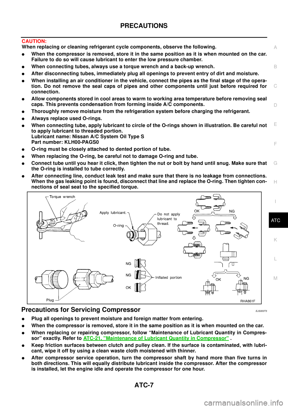
CAUTION:
When replacing or cleaning refrigerant cycle components, observe the following.
lWhen the compressor is removed, store it in the same position as it is when mounted on the car.
Failure to do so will cause lubricant to enter the low pressure chamber.
lWhen connecting tubes, always use a torque wrench and a back-up wrench.
lAfter disconnecting tubes, immediately plug all openings to prevent entry of dirt and moisture.
lWhen installing an air conditioner in the vehicle, connect the pipes as the final stage of the opera-
tion. Do not remove the seal caps of pipes and other components until just before required for
connection.
lAllow components stored in cool areas to warm to working area temperature before removing seal
caps. This prevents condensation from forming inside A/C components.
lThoroughly remove moisture from the refrigeration system before charging the refrigerant.
lAlways replace used O-rings.
lWhen connecting tube, apply lubricant to circle of the O-rings shown in illustration. Be careful not
to apply lubricant to threaded portion.
Lubricant name: Nissan A/C System Oil Type S
Part number: KLH00-PAGS0
lO-ring must be closely attached to dented portion of tube.
lWhen replacing the O-ring, be careful not to damage O-ring and tube.
lConnect tube until you hear it click, then tighten the nut or bolt by hand until snug. Make sure that
the O-ring is installed to tube correctly.
lAfter connecting line, conduct leak test and make sure that there is no leakage from connections.
When the gas leaking point is found, disconnect that line and replace the O-ring. Then tighten con-
nections of seal seat to the specified torque.
Precautions for Servicing CompressorEJS000T5
lPlug all openings to prevent moisture and foreign matter from entering.
lWhen the compressor is removed, store it in the same position as it is when mounted on the car.
lWhen replacing or repairing compressor, follow “Maintenance of Lubricant Quantity in Compres-
sor” exactly. Refer toATC-21, "
Maintenance of Lubricant Quantity in Compressor".
lKeep friction surfaces between clutch and pulley clean. If the surface is contaminated, with lubri-
cant, wipe it off by using a clean waste cloth moistened with thinner.
lAfter compressor service operation, turn the compressor shaft by hand more than five turns in
both directions. This will equally distribute lubricant inside the compressor. After the compressor
is installed, let the engine idle and operate the compressor for one hour.
RHA861F
Page 586 of 3066
ATC-8
PRECAUTIONS
lAfter replacing the compressor magnet clutch, apply voltage to the new one and check for normal
operation.
Precautions for Service EquipmentEJS000T6
RECOVERY/RECYCLING EQUIPMENT
Be certain to follow the manufacturers instructions for machine operation and machine maintenance. Never
introduce any refrigerant other than that specified into the machine.
ELECTRONIC LEAK DETECTOR
Be certain to follow the manufacturer's instructions for tester operation and tester maintenance.
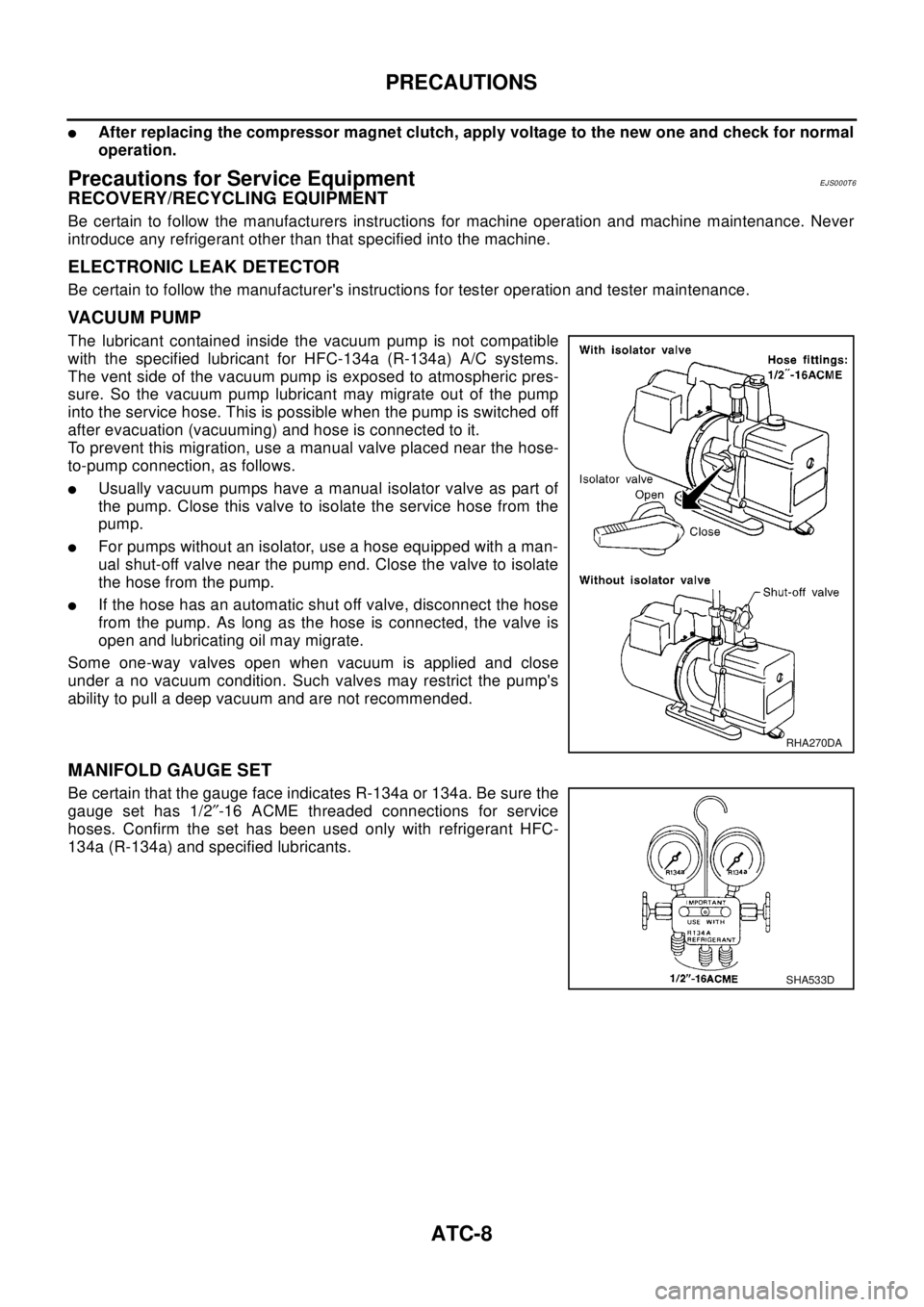
VACUUM PUMP
The lubricant contained inside the vacuum pump is not compatible
with the specified lubricant for HFC-134a (R-134a) A/C systems.
The vent side of the vacuum pump is exposed to atmospheric pres-
sure. So the vacuum pump lubricant may migrate out of the pump
into the service hose. This is possible when the pump is switched off
after evacuation (vacuuming) and hose is connected to it.
To prevent this migration, use a manual valve placed near the hose-
to-pump connection, as follows.
lUsually vacuum pumps have a manual isolator valve as part of
the pump. Close this valve to isolate the service hose from the
pump.
lFor pumps without an isolator, use a hose equipped with a man-
ual shut-off valve near the pump end. Close the valve to isolate
the hose from the pump.
lIf the hose has an automatic shut off valve, disconnect the hose
from the pump. As long as the hose is connected, the valve is
open and lubricating oil may migrate.
Some one-way valves open when vacuum is applied and close
under a no vacuum condition. Such valves may restrict the pump's
ability to pull a deep vacuum and are not recommended.
MANIFOLD GAUGE SET
Be certain that the gauge face indicates R-134a or 134a. Be sure the
gauge set has 1/2²-16 ACME threaded connections for service
hoses. Confirm the set has been used only with refrigerant HFC-
134a (R-134a) and specified lubricants.
RHA270DA
SHA533D
Page 599 of 3066
LUBRICANT
ATC-21
C
D
E
F
G
H
I
K
L
MA
B
AT C
LUBRICANTPFP:KLG00
Maintenance of Lubricant Quantity in CompressorEJS000TH
The lubricant in the compressor circulates through the system with the refrigerant. Add lubricant to compres-
sor when replacing any component or after a large gas leakage occurred. It is important to maintain the speci-
fied amount.
If lubricant quantity is not maintained properly, the following malfunctions may result:
lLack of lubricant: May lead to a seized compressor
lExcessive lubricant: Inadequate cooling (thermal exchange interference)
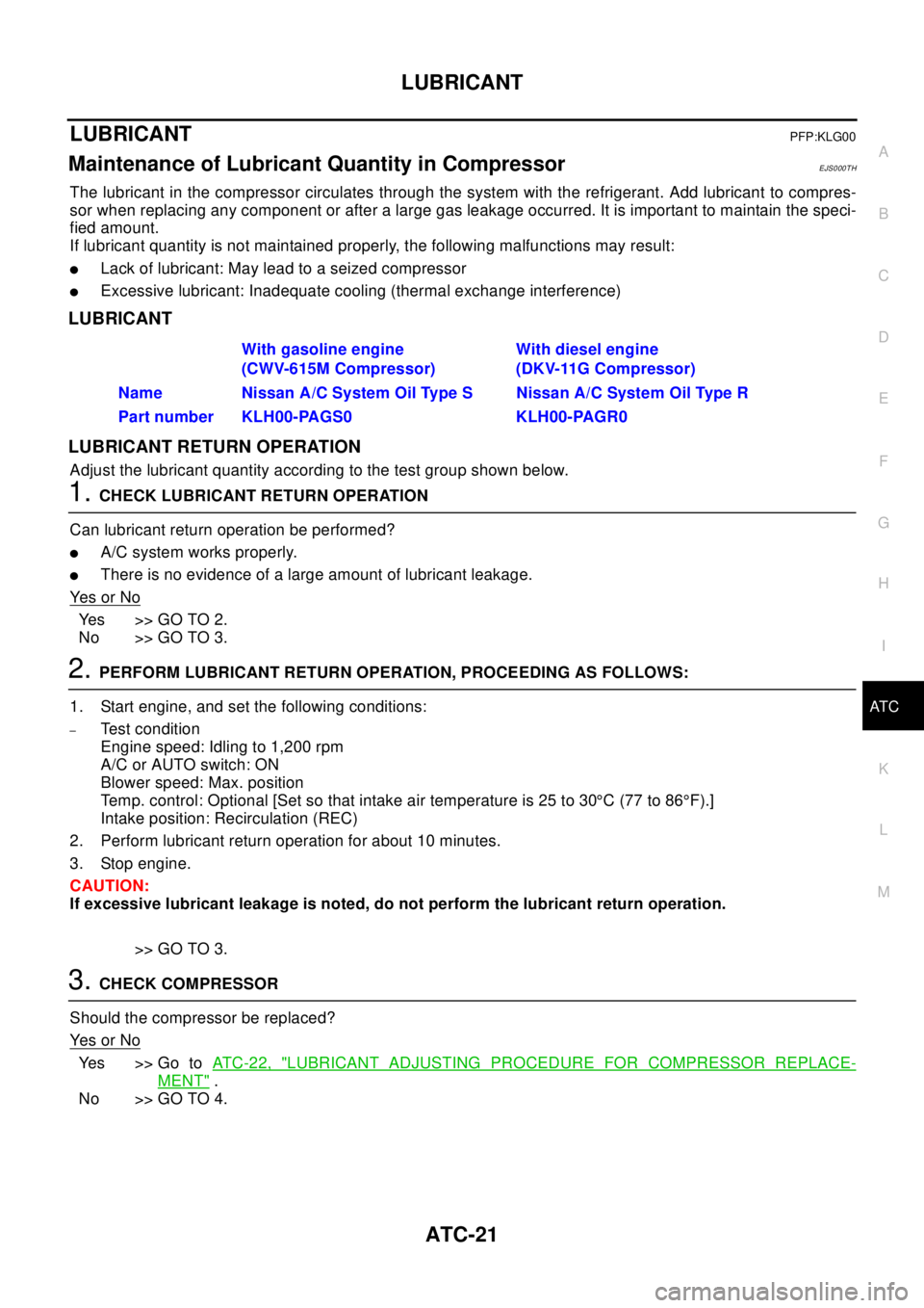
LUBRICANT
LUBRICANT RETURN OPERATION
Adjust the lubricant quantity according to the test group shown below.
1.CHECK LUBRICANT RETURN OPERATION
Can lubricant return operation be performed?
lA/C system works properly.
lThere is no evidence of a large amount of lubricant leakage.
Ye s o r N o
Yes >>GOTO2.
No >> GO TO 3.
2.PERFORM LUBRICANT RETURN OPERATION, PROCEEDING AS FOLLOWS:
1. Start engine, and set the following conditions:
–Test condition
Engine speed: Idling to 1,200 rpm
A/C or AUTO switch: ON
Blower speed: Max. position
Temp. control: Optional [Set so that intake air temperature is 25 to 30°C (77 to 86°F).]
Intake position: Recirculation (REC)
2. Perform lubricant return operation for about 10 minutes.
3. Stop engine.
CAUTION:
If excessive lubricant leakage is noted, do not perform the lubricant return operation.
>> GO TO 3.
3.CHECK COMPRESSOR
Should the compressor be replaced?
Ye s o r N o
Ye s > > G o t oAT C - 2 2 , "LUBRICANT ADJUSTING PROCEDURE FOR COMPRESSOR REPLACE-
MENT".
No >> GO TO 4.With gasoline engine
(CWV-615M Compressor)With diesel engine
(DKV-11G Compressor)
Name Nissan A/C System Oil Type S Nissan A/C System Oil Type R
Part number KLH00-PAGS0 KLH00-PAGR0
Page 670 of 3066
ATC-92
TROUBLE DIAGNOSIS
Self-diagnosis
EJS001H9
Symptom: Self-diagnosis can not be performed.
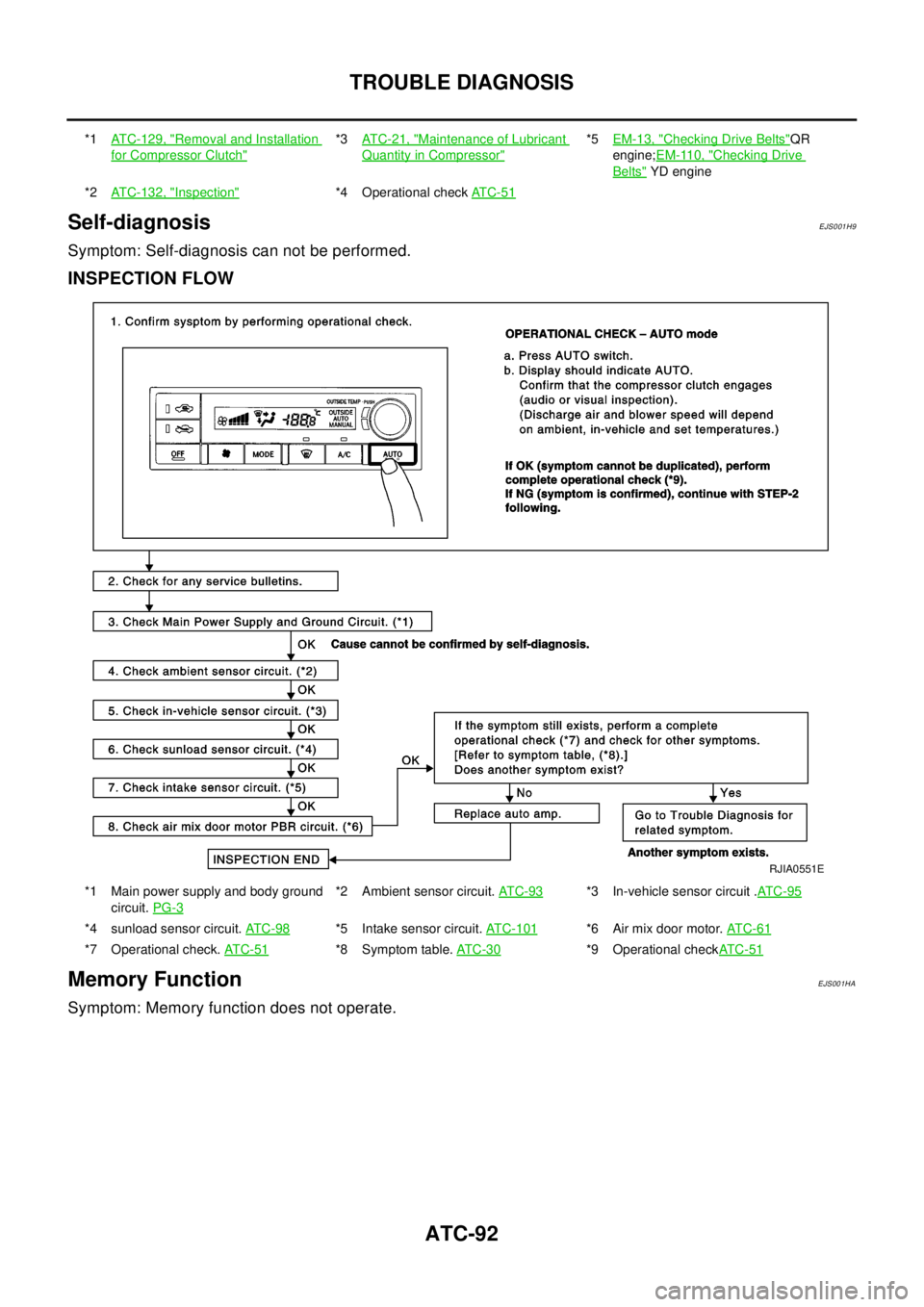
INSPECTION FLOW
Memory FunctionEJS001HA
Symptom: Memory function does not operate.
*1ATC-129, "Removal and Installation
for Compressor Clutch"
*3AT C - 2 1 , "Maintenance of Lubricant
Quantity in Compressor"
*5EM-13, "Checking Drive Belts"QR
engine;EM-110, "
Checking Drive
Belts"YD engine
*2ATC-132, "
Inspection"*4 Operational checkAT C - 5 1
*1 Main power supply and body ground
circuit.PG-3*2 Ambient sensor circuit.AT C - 9 3*3 In-vehicle sensor circuit .AT C - 9 5
*4 sunload sensor circuit.AT C - 9 8*5 Intake sensor circuit.AT C - 1 0 1*6 Air mix door motor.AT C - 6 1
*7 Operational check.AT C - 5 1*8 Symptom table.AT C -3 0*9 Operational checkAT C - 5 1
RJIA0551E
Page 692 of 3066
ATC-114
VENTILATION AIR FILTER
VENTILATION AIR FILTER
PFP:27277
Removal and InstallationEJS000UP
FunctionEJS000UQ
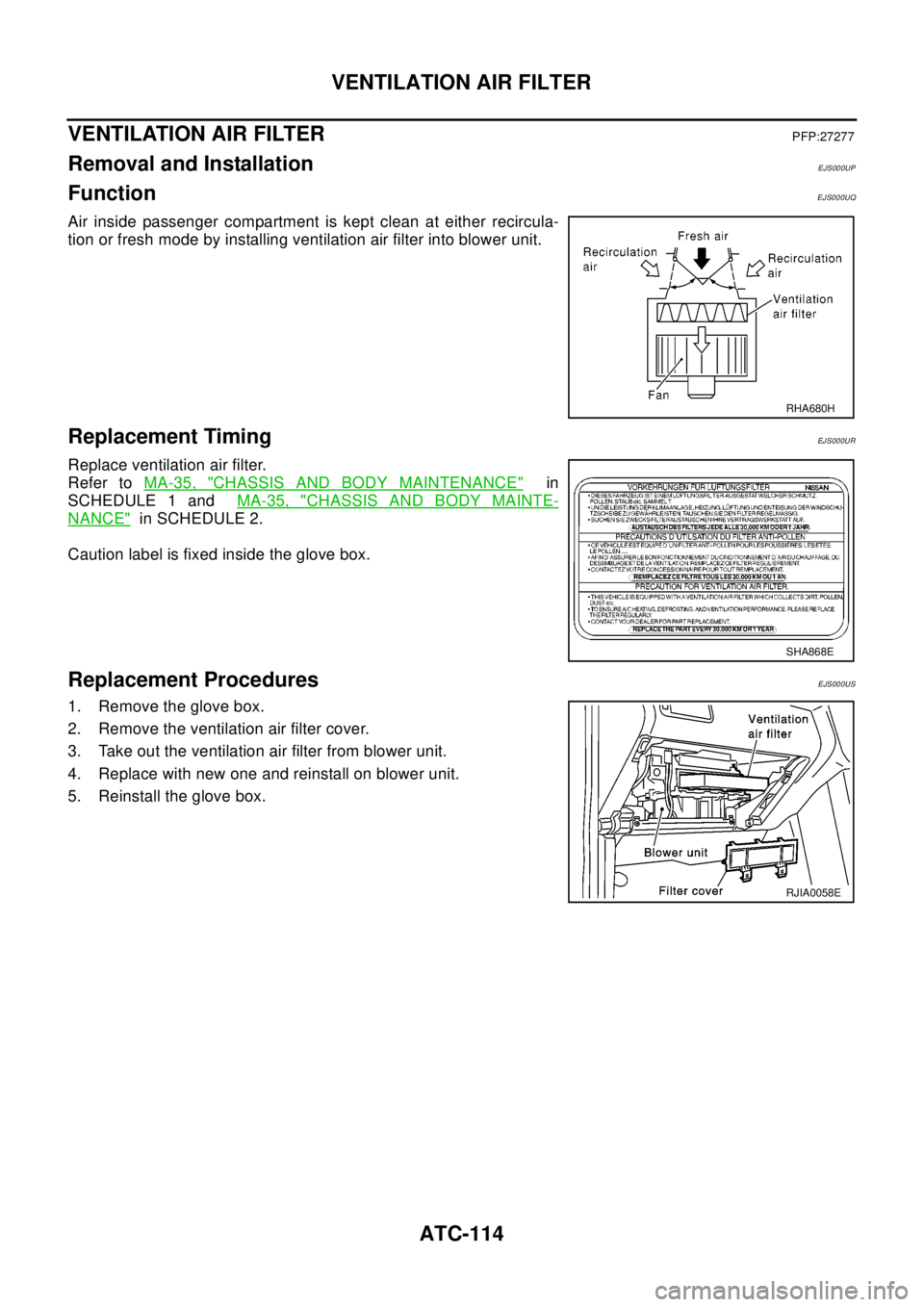
Air inside passenger compartment is kept clean at either recircula-
tion or fresh mode by installing ventilation air filter into blower unit.
Replacement TimingEJ S00 0UR
Replace ventilation air filter.
Refer toMA-35, "
CHASSIS AND BODY MAINTENANCE"in
SCHEDULE 1 andMA-35, "
CHASSIS AND BODY MAINTE-
NANCE"in SCHEDULE 2.
Caution label is fixed inside the glove box.
Replacement ProceduresEJS000US
1. Remove the glove box.
2. Remove the ventilation air filter cover.
3. Take out the ventilation air filter from blower unit.
4. Replace with new one and reinstall on blower unit.
5. Reinstall the glove box.
RHA680H
SHA868E
RJIA0058E