CRANK NISSAN X-TRAIL 2003 Electronic Repair Manual
[x] Cancel search | Manufacturer: NISSAN, Model Year: 2003, Model line: X-TRAIL, Model: NISSAN X-TRAIL 2003Pages: 3066, PDF Size: 51.47 MB
Page 13 of 3066
PRECAUTIONS
AT-7
D
E
F
G
H
I
J
K
L
MA
B
AT
lAfter performing each TROUBLE DIAGNOSIS, perform
“DTC (Diagnostic Trouble Code) CONFIRMATION PROCE-
DURE”.
The DTC should not be displayed in the “DTC CONFIRMA-
TION PROCEDURE” if the repair is completed.
lBefore proceeding with disassembly, thoroughly clean the out-
side of the transaxle. It is important to prevent the internal parts
from becoming contaminated by dirt or other foreign matter.
lDisassembly should be done in a clean work area.
lUse lint-free cloth or towels for wiping parts clean. Common
shop rags can leave fibers that could interfere with the operation
of the transaxle.
lPlace disassembled parts in order for easier and proper assembly.
lAll parts should be carefully cleaned with a general purpose, non-flammable solvent before inspection or
reassembly.
lGaskets, seals and O-rings should be replaced any time the transaxle is disassembled.
lIt is very important to perform functional tests whenever they are indicated.
lThe valve body contains precision parts and requires extreme care when parts are removed and serviced.
Place disassembled valve body parts in order for easier and proper assembly. Care will also prevent
springs and small parts from becoming scattered or lost.
lProperly installed valves, sleeves, plugs, etc. will slide along bores in valve body under their own weight.
lBefore assembly, apply a coat of recommended ATF to all parts. Apply petroleum jelly to protect O-rings
and seals, or hold bearings and washers in place during assembly. Do not use grease.
lExtreme care should be taken to avoid damage to O-rings, seals and gaskets when assembling.
lAfter overhaul, refill the transaxle with new ATF.
lWhen the A/T drain plug is removed, only some of the fluid is drained. Old A/T fluid will remain in torque
converter and ATF cooling system.
Always follow the procedures under “Changing A/T Fluid” in the AT section when changing A/T fluid. Refer
to “Changing A/T Fluid”,AT-13, "
A/T FLUID".
Service Notice or PrecautionsECS004Q3
FAI L-S AFE
The TCM has an electronic Fail-Safe (limp home mode). This allows the vehicle to be driven even if a major
electrical input/output device circuit is damaged.
Under Fail-Safe, the vehicle always runs in third gear, even with a shift lever position of “1”, “2” or “D”. The cus-
tomer may complain of sluggish or poor acceleration.
When the ignition key is turned “ON” following Fail-Safe operation, O/D OFF indicator lamp blinks for about 8
seconds. Refer to SELF-DIAGNOSTIC PROCEDURE(WITHOUT CONSULT-II)",AT- 2 7 3 , "
Diagnostic Proce-
dure Without CONSULT-II"(EXCEPT FOR EURO-OBD) or "TCM Self-diagnostic Procedure(NO TOOLS)",
AT- 5 1 , "
TCM SELF-DIAGNOSTIC PROCEDURE (NO TOOLS)"(EURO-OBD).
The blinking of the O/D OFF indicator lamp for about 8 seconds will appear only once and be cleared. The
customer may resume normal driving conditions.
Always follow the “WORK FLOW”, refer toAT-284, "
Work Flow"(EXCEPT FOR Euro-OBD) orAT-61, "Work
Flow"(Euro-OBD).
The SELF-DIAGNOSIS results will be as follows:
lThe first SELF-DIAGNOSIS will indicate damage to the vehicle speed sensor or the revolution sensor.
lDuring the next SELF-DIAGNOSIS, performed after checking the sensor, no damages will be indicated.
TORQUE CONVERTER SERVICE
The torque converter should be replaced under any of the following conditions:
lExternal leaks in the hub weld area.
lConverter hub is scored or damaged.
lConverter pilot is broken, damaged or fits poorly into crankshaft.
lSteel particles are found after flushing the cooler and cooler lines.
lPump is damaged or steel particles are found in the converter.
SAT652J
Page 464 of 3066
![NISSAN X-TRAIL 2003 Electronic Repair Manual AT-458
[ALL]
REMOVAL AND INSTALLATION
REMOVAL AND INSTALLATION
PFP:00000
RemovalECS004NC
CAUTION:
Before separating transaxle from engine, remove the crankshaft position sensor (Euro-OBD) from
transax](/img/5/57402/w960_57402-463.png "NISSAN X-TRAIL 2003 Electronic Repair Manual AT-458
[ALL]
REMOVAL AND INSTALLATION
REMOVAL AND INSTALLATION
PFP:00000
RemovalECS004NC
CAUTION:
Before separating transaxle from engine, remove the crankshaft position sensor (Euro-OBD) from
transax")
AT-458
[ALL]
REMOVAL AND INSTALLATION
REMOVAL AND INSTALLATION
PFP:00000
RemovalECS004NC
CAUTION:
Before separating transaxle from engine, remove the crankshaft position sensor (Euro-OBD) from
transaxle. Be careful not to damage sensor.
1. Remove battery and bracket, air cleaner and air duct.
2. Remove air breather hose.
3. Disconnect A/T solenoid valve harness connector, PNP switch harness connector and revolution sensor
harness connector.
4. Remove crankshaft position sensor (Euro-OBD) from transaxle.
5. Disconnect control cable from transaxle.
6. Remove front exhaust tube.
7. Disconnect oil cooler hoses.
8. Remove drive shafts. Refer toFAX-11, "
FRONT DRIVE
SHAFT",RAX-9, "REAR DRIVE SHAFT".
9. Remove transfer. Refer toTF-12, "
TRANSFER ASSEMBLY".
10. Remove starter motor from transaxle.
11. Support transaxle with a jack.
SCIA0793E
ATM0479D
Page 465 of 3066
![NISSAN X-TRAIL 2003 Electronic Repair Manual REMOVAL AND INSTALLATION
AT-459
[ALL]
D
E
F
G
H
I
J
K
L
MA
B
AT
12. Remove center member, engine insulator and engine mounting
bracket.
lTighten center member fixing bolts to specified torque, Refer
t](/img/5/57402/w960_57402-464.png "NISSAN X-TRAIL 2003 Electronic Repair Manual REMOVAL AND INSTALLATION
AT-459
[ALL]
D
E
F
G
H
I
J
K
L
MA
B
AT
12. Remove center member, engine insulator and engine mounting
bracket.
lTighten center member fixing bolts to specified torque, Refer
t")
REMOVAL AND INSTALLATION
AT-459
[ALL]
D
E
F
G
H
I
J
K
L
MA
B
AT
12. Remove center member, engine insulator and engine mounting
bracket.
lTighten center member fixing bolts to specified torque, Refer
toEM-61, "
ENGINE ASSEMBLY".
13. Remove suspension member. Refer toFSU-12, "
FRONT SUS-
PENSION MEMBER".
14. Remove dust cover from converter housing.
Rotate crankshaft to gain access to securing bolts.
15. Remove securing bolts between drive plate and torque con-
verter. when crank shaft rotates, turn to right at the front side of
engine.
16. Support engine with a jack.
17. Remove bolts fixing transaxle to engine.
18. Lower transaxle while supporting it with a jack.
InstallationECS004ND
1. Check drive plate runout.
CAUTION:
Do not allow any magnetic materials to contact the ring
gear teeth.
lIf this runout is out of allowance, replace drive plate with ring
gear.
2. When connecting torque converter to transaxle, measure dis-
tance “A” to be certain that they are correctly assembled.
SCIA0794E
AAT259A
Maximum allowable runout :
Refer to EM-´´, “FLYWHEEL/DRIVE PLATE RUNOUT”.
SAT977H
Distance “A”: 19 mm (0.626 in) or more
SAT573D
Page 466 of 3066
![NISSAN X-TRAIL 2003 Electronic Repair Manual AT-460
[ALL]
REMOVAL AND INSTALLATION
3. Install torque converter to drive plate.
lWith converter installed, rotate crankshaft several turns
to check that transaxle rotates freely without binding.
4.](/img/5/57402/w960_57402-465.png "NISSAN X-TRAIL 2003 Electronic Repair Manual AT-460
[ALL]
REMOVAL AND INSTALLATION
3. Install torque converter to drive plate.
lWith converter installed, rotate crankshaft several turns
to check that transaxle rotates freely without binding.
4.")
AT-460
[ALL]
REMOVAL AND INSTALLATION
3. Install torque converter to drive plate.
lWith converter installed, rotate crankshaft several turns
to check that transaxle rotates freely without binding.
4. Tighten belts fixing transaxle.
5. Reinstall any part removed.
6. Adjust control cable. Refer toAT-456, "
Control Cable Adjust-
ment".
7. Check continuity of PNP switch. Refer toAT-130, "
DTC P0705
PARK/NEUTRAL POSITION (PNP) SWITCH".
8. Refill transaxle with ATF and check fluid level.
9. Move selector lever through all positions to be sure that tran-
saxle operates correctly. With parking brake applied, idle
engine. Move selector lever through “N” to “D”, to “2”, to “1” and
“R” positions. A slight shock should be felt through the hand
gripping the selector each time the transaxle is shifted.
10. Perform road test. Refer toAT-69, "
Road Test".
AAT266A
Bolt No.Tightening torque
N-m (kg-m, ft-lb)Bolt length “ L ”
mm (in)
1
69.6 - 79.4 (7.1 - 8.1, 51.4 - 58.6)49 (1.93)
245(1.77)
3
39.2 - 46.1 (4.0 - 4.7, 29.0 - 34.0)40 (1.57)
430(1.18)
5
30.4 - 40.2 (3.1 - 4.1, 22.4 - 29.7)40 (1.57)
645(1.97)
SCIA0795E
SAT638A
Page 596 of 3066
ATC-18
REFRIGERATION SYSTEM
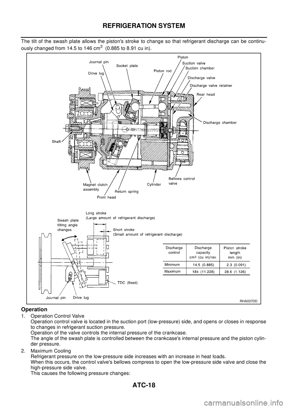
The tilt of the swash plate allows the piston's stroke to change so that refrigerant discharge can be continu-
ously changed from 14.5 to 146 cm
3(0.885 to 8.91 cu in).
Operation
1. Operation Control Valve
Operation control valve is located in the suction port (low-pressure) side, and opens or closes in response
to changes in refrigerant suction pressure.
Operation of the valve controls the internal pressure of the crankcase.
The angle of the swash plate is controlled between the crankcase's internal pressure and the piston cylin-
der pressure.
2. Maximum Cooling
Refrigerant pressure on the low-pressure side increases with an increase in heat loads.
When this occurs, the control valve's bellows compress to open the low-pressure side valve and close the
high-pressure side valve.
This causes the following pressure changes:
RHA037DD
Page 597 of 3066
REFRIGERATION SYSTEM
ATC-19
C
D
E
F
G
H
I
K
L
MA
B
AT C
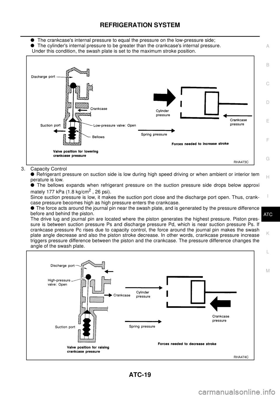
lThe crankcase's internal pressure to equal the pressure on the low-pressure side;
lThe cylinder's internal pressure to be greater than the crankcase's internal pressure.
Under this condition, the swash plate is set to the maximum stroke position.
3. Capacity Control
lRefrigerant pressure on suction side is low during high speed driving or when ambient or interior tem
perature is low.
lThe bellows expands when refrigerant pressure on the suction pressure side drops below approxi
mately 177 kPa (1.8 kg/cm
2,26psi).
Since suction pressure is low, it makes the suction port close and the discharge port open. Thus, crank-
case pressure becomes high as high pressure enters the crankcase.
lThe force acts around the journal pin near the swash plate, and is generated by the pressure difference
before and behind the piston.
The drive lug and journal pin are located where the piston generates the highest pressure. Piston pres-
sure is between suction pressure Ps and discharge pressure Pd, which is near suction pressure Ps. If
crankcase pressure Pc rises due to capacity control, the force around the journal pin makes the swash
plate angle decrease and also the piston stroke decrease. In other words, crankcase pressure increase
triggers pressure difference between the piston and the crankcase. The pressure difference changes the
angle of the swash plate.
RHA473C
RHA474C
Page 799 of 3066
FRONT DOOR LOCK
BL-55
C
D
E
F
G
H
J
K
L
MA
B
BL
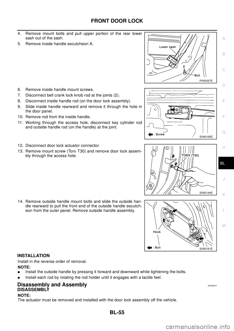
4. Remove mount bolts and pull upper portion of the rear lower
sash out of the sash.
5. Remove inside handle escutcheon A.
6. Remove inside handle mount screws.
7. Disconnect bell crank lock knob rod at the joints (2).
8. Disconnect inside handle rod (on the door lock assembly).
9. Slide inside handle rearward and remove it through the hole in
the door panel.
10. Remove rod from the inside handle.
11. Working through the access hole, disconnect key cylinder rod
and outside handle rod (on the handle) at the joint.
12. Disconnect door lock actuator connector.
13. Remove mount screw (Torx T30) and remove door lock assem-
bly through the access hole.
14. Remove outside handle mount bolts and slide the outside han-
dle rearward to pull the front end of the outside handle escutch-
eon from the outer panel. Remove outside handle assembly.
INSTALLATION
Install in the reverse order of removal.
NOTE:
lInstall the outside handle by pressing it forward and downward while tightening the bolts.
lInstall each rod by rotating the rod holder until it engages with a tactile feel.
Disassembly and AssemblyEIS000KY
DISASSEMBLY
NOTE:
The actuator must be removed and installed with the door lock assembly off the vehicle.
PIIA0557E
SIIA0160E
SIIA0144E
SIIA0161E
Page 1119 of 3066

EC-5
C
D
E
F
G
H
I
J
K
L
M
ECA DTC P1805 BRAKE SWITCH ................................ 329
Description ........................................................... 329
CONSULT-II Reference Value in Data Monitor Mode
. 329
ECM Terminals and Reference Value .................. 329
On Board Diagnosis Logic ................................... 329
DTC Confirmation Procedure ............................... 329
Wiring Diagram .................................................... 330
Diagnostic Procedure ........................................... 331
Component Inspection ......................................... 332
IGNITION SIGNAL .................................................. 334
Component Description ........................................ 334
ECM Terminals and Reference Value .................. 334
Wiring Diagram .................................................... 335
Diagnostic Procedure ........................................... 337
Component Inspection ......................................... 341
Removal and Installation ...................................... 342
INJECTOR CIRCUIT ............................................... 343
Component Description ........................................ 343
CONSULT-II Reference Value in Data Monitor Mode
. 343
ECM Terminals and Reference Value .................. 343
Wiring Diagram .................................................... 344
Diagnostic Procedure ........................................... 345
Component Inspection ......................................... 347
Removal and Installation ...................................... 347
START SIGNAL ...................................................... 348
CONSULT-II Reference Value in Data Monitor Mode
. 348
ECM Terminals and Reference Value .................. 348
Wiring Diagram .................................................... 349
Diagnostic Procedure ........................................... 350
FUEL PUMP CIRCUIT ............................................ 352
Description ........................................................... 352
CONSULT-II Reference Value in Data Monitor Mode
. 352
ECM Terminals and Reference Value .................. 352
Wiring Diagram .................................................... 354
Diagnostic Procedure ........................................... 355
Component Inspection ......................................... 357
Removal and Installation ...................................... 358
REFRIGERANT PRESSURE SENSOR ................. 359
Component Description ........................................ 359
ECM Terminals and Reference Value .................. 359
Wiring Diagram .................................................... 360
Diagnostic Procedure ........................................... 361
Removal and Installation ...................................... 362
ELECTRICAL LOAD SIGNAL ................................ 363
CONSULT-II Reference Value in Data Monitor Mode
. 363
ECM Terminals and Reference Value .................. 363
Wiring Diagram .................................................... 364
Diagnostic Procedure ........................................... 366
DATA LINK CONNECTOR ..................................... 371
Wiring Diagram .................................................... 371
EVAPORATIVE EMISSION SYSTEM ..................... 372
Description ........................................................... 372
Component Inspection ......................................... 374POSITIVE CRANKCASE VENTILATION ...............375
Description ............................................................375
Component Inspection ..........................................375
SERVICE DATA AND SPECIFICATIONS (SDS) ....377
Fuel Pressure .......................................................377
Idle Speed and Ignition Timing .............................377
Calculated Load Value ..........................................377
Mass Air Flow Sensor ...........................................377
Intake Air Temperature Sensor .............................377
Engine Coolant Temperature Sensor ...................377
Heated Oxygen Sensor 1 Heater .........................377
Heated Oxygen sensor 2 Heater ..........................377
Crankshaft Position Sensor (POS) .......................377
Camshaft Position Sensor (PHASE) ....................377
Throttle Control Motor ...........................................378
Injector ..................................................................378
Fuel Pump ............................................................378
QR (WITHOUT EURO-OBD)
INDEX FOR DTC .....................................................379
Alphabetical Index ................................................379
DTC No. Index ......................................................380
PRECAUTIONS ......................................................381
Precautions for Supplemental Restraint System
(SRS) “AIR BAG” and “SEAT BELT PRE-TEN-
SIONER” ...............................................................381
On Board Diagnostic (OBD) System of Engine and
A/T ........................................................................381
Precaution ............................................................381
Wiring Diagrams and Trouble Diagnosis ..............384
PREPARATION .......................................................385
Special Service Tools ...........................................385
Commercial Service Tools ....................................385
ENGINE CONTROL SYSTEM ................................387
System Diagram ...................................................387
Vacuum Hose Drawing .........................................388
System Chart ........................................................389
Multiport Fuel Injection (MFI) System ...................389
Electronic Ignition (EI) System .............................392
Air Conditioning Cut Control .................................392
Fuel Cut Control (at No Load and High Engine
Speed) ..................................................................393
CAN communication .............................................393
BASIC SERVICE PROCEDURE .............................395
Idle Speed and Ignition Timing Check ..................395
Throttle Valve Closed Position Learning ...............396
Accelerator Pedal Released Position Learning ....396
Idle Air Volume Learning ......................................396
Fuel Pressure Check ............................................399
ON BOARD DIAGNOSTIC (OBD) SYSTEM ..........401
Introduction ...........................................................401
Two Trip Detection Logic ......................................401
Emission-related Diagnostic Information ..............401
NATS (Nissan Anti-theft System) .........................403
Malfunction Indicator (MI) .....................................404
TROUBLE DIAGNOSIS ..........................................407
Trouble Diagnosis Introduction .............................407
Page 1122 of 3066

EC-8
Component Inspection ..........................................584
Removal and Installation ......................................586
HO2S2 .....................................................................587
Component Description ........................................587
CONSULT-II Reference Value in Data Monitor Mode
.587
ECM Terminals and Reference Value ...................587
Wiring Diagram .....................................................588
Diagnostic Procedure ...........................................589
Component Inspection ..........................................590
Removal and Installation ......................................591
IGNITION SIGNAL ..................................................592
Component Description ........................................592
ECM Terminals and Reference Value ...................592
Wiring Diagram .....................................................593
Diagnostic Procedure ...........................................595
Component Inspection ..........................................599
Removal and Installation ......................................600
EVAP CANISTER PURGE VOLUME CONTROL
SOLENOID VALVE .................................................601
Description ............................................................601
CONSULT-II Reference Value in Data Monitor Mode
.601
ECM Terminals and Reference Value ...................601
Wiring Diagram .....................................................603
Diagnostic Procedure ...........................................604
Component Inspection ..........................................607
Removal and Installation ......................................607
IVT CONTROL SOLENOID VALVE ........................608
Description ............................................................608
CONSULT-II Reference Value in Data Monitor Mode
.608
ECM Terminals and Reference Value ...................609
Wiring Diagram .....................................................610
Diagnostic Procedure ...........................................611
Component Inspection ..........................................613
Removal and Installation ......................................613
PNP SWITCH ..........................................................614
Component Description ........................................614
CONSULT-II Reference Value in Data Monitor Mode
.614
ECM Terminals and Reference Value ...................614
Wiring Diagram .....................................................615
Diagnostic Procedure ...........................................616
INJECTOR CIRCUIT ...............................................618
Component Description ........................................618
CONSULT-II Reference Value in Data Monitor Mode
.618
ECM Terminals and Reference Value ...................618
Wiring Diagram .....................................................619
Diagnostic Procedure ...........................................620
Component Inspection ..........................................622
Removal and Installation ......................................622
START SIGNAL ......................................................623
CONSULT-II Reference Value in Data Monitor Mode
.623
ECM Terminals and Reference Value ...................623Wiring Diagram ..................................................... 624
Diagnostic Procedure ............................................ 625
FUEL PUMP CIRCUIT ............................................. 627
Description ............................................................ 627
CONSULT-II Reference Value in Data Monitor Mode
. 627
ECM Terminals and Reference Value ................... 627
Wiring Diagram ..................................................... 629
Diagnostic Procedure ............................................ 630
Component Inspection .......................................... 632
Removal and Installation ....................................... 633
REFRIGERANT PRESSURE SENSOR .................. 634
Component Description ........................................ 634
ECM Terminals and Reference Value ................... 634
Wiring Diagram ..................................................... 635
Diagnostic Procedure ............................................ 636
Removal and Installation ....................................... 637
ELECTRICAL LOAD SIGNAL ................................ 638
CONSULT-II Reference Value in Data Monitor Mode
. 638
ECM Terminals and Reference Value ................... 638
Wiring Diagram ..................................................... 639
Diagnostic Procedure ............................................ 641
DATA LINK CONNECTOR ...................................... 646
Wiring Diagram ..................................................... 646
EVAPORATIVE EMISSION SYSTEM ..................... 647
Description ............................................................ 647
Component Inspection .......................................... 649
POSITIVE CRANKCASE VENTILATION ................ 650
Description ............................................................ 650
Component Inspection .......................................... 650
SERVICE DATA AND SPECIFICATIONS (SDS) .... 652
Fuel Pressure ........................................................ 652
Idle Speed and Ignition Timing .............................. 652
Calculated Load Value .......................................... 652
Mass Air Flow Sensor ........................................... 652
Intake Air Temperature Sensor ............................. 652
Engine Coolant Temperature Sensor .................... 652
Heated Oxygen Sensor 1 Heater .......................... 652
Heated Oxygen sensor 2 Heater .......................... 652
Crankshaft Position Sensor (POS) ....................... 652
Camshaft Position Sensor (PHASE) ..................... 652
Throttle Control Motor ........................................... 653
Injector .................................................................. 653
Fuel Pump ............................................................. 653
YD
INDEX FOR DTC ..................................................... 654
Alphabetical Index ................................................. 654
DTC No. Index ...................................................... 654
PRECAUTIONS ....................................................... 656
Precautions for Supplemental Restraint System
(SRS) “AIR BAG” and “SEAT BELT PRE-TEN-
SIONER” ............................................................... 656
Precautions ........................................................... 656
Wiring Diagrams and Trouble Diagnosis ............... 658
Page 1123 of 3066

EC-9
C
D
E
F
G
H
I
J
K
L
M
ECA ENGINE CONTROL SYSTEM ................................ 659
System Diagram ................................................... 659
System Chart ....................................................... 660
Fuel Injection Control System .............................. 660
Fuel Injection Timing Control System ................... 662
Air Conditioning Cut Control ................................. 662
Fuel Cut Control (At No Load & High Engine Speed). 662
Crankcase Ventilation System ............................. 663
BASIC SERVICE PROCEDURE ............................ 664
Fuel Filter ............................................................. 664
Accelerator Pedal Released Position Learning .... 664
Fuel Pressure Relief Valve ................................... 665
ON BOARD DIAGNOSTIC (OBD) SYSTEM .......... 666
DTC and MI Detection Logic ................................ 666
Diagnostic Trouble Code (DTC) ........................... 666
NATS (Nissan Anti-theft System) ......................... 666
Malfunction Indicator (MI) ..................................... 667
TROUBLE DIAGNOSIS .......................................... 669
Trouble Diagnosis Introduction ............................. 669
Basic Inspection ................................................... 672
Symptom Matrix Chart ......................................... 676
Engine Control Component Parts Location .......... 680
Circuit Diagram .................................................... 683
ECM Harness Connector Terminal Layout ........... 685
ECM Terminals And Reference Value .................. 685
CONSULT-II Function .......................................... 691
CONSULT-II Reference Value in Data Monitor Mode
. 696
Major Sensor Reference Graph in Data Monitor
Mode .................................................................... 698
TROUBLE DIAGNOSIS FOR INTERMITTENT INCI-
DENT ...................................................................... 699
Description ........................................................... 699
Diagnostic Procedure ........................................... 699
POWER SUPPLY CIRCUIT FOR ECM .................. 700
ECM Terminals and Reference Value .................. 700
Wiring Diagram .................................................... 701
Diagnostic Procedure ........................................... 702
Component Inspection ......................................... 705
DTCP0100MASSAIRFLOWSENSOR(MAFS).. 706
Component Description ........................................ 706
CONSULT-II Reference Value in Data Monitor Mode
. 706
ECM Terminals and Reference Value .................. 706
On Board Diagnosis Logic ................................... 707
DTC Confirmation Procedure ............................... 707
Wiring Diagram .................................................... 708
Diagnostic Procedure ........................................... 709
Component Inspection ......................................... 710
Removal and Installation ...................................... 710
DTC P0115 ENGINE COOLANT TEMPERATURE
(ECT) SENSOR (CIRCUIT) ...................................... 711
Description ............................................................ 711
On Board Diagnosis Logic .................................... 711
DTC Confirmation Procedure ................................ 711
Wiring Diagram .................................................... 712
Diagnostic Procedure ........................................... 713Component Inspection ..........................................714
Removal and Installation ......................................714
DTC P0120 ACCELERATOR PEDAL POSITION
SENSOR .................................................................715
Description ............................................................715
CONSULT-II Reference Value in Data Monitor Mode
.715
ECM Terminals and Reference Value ...................715
On Board Diagnosis Logic ....................................716
DTC Confirmation Procedure ...............................716
Wiring Diagram .....................................................717
Diagnostic Procedure ...........................................718
Component Inspection ..........................................721
Removal and Installation ......................................722
DTC P0190 COMMON RAIL FUEL PRESSURE
SENSOR .................................................................723
Description ............................................................723
CONSULT-II Reference Value in Data Monitor Mode
.723
ECM Terminals and Reference Value ...................723
On Board Diagnosis Logic ....................................723
DTC Confirmation Procedure ...............................723
Wiring Diagram .....................................................724
Diagnostic Procedure ...........................................725
Component Inspection ..........................................726
Removal and Installation ......................................726
DTC P0201 - P0204 FUEL INJECTOR ...................727
Description ............................................................727
CONSULT-II Reference Value in Data Monitor Mode
.727
ECM Terminals and Reference Value ...................727
On Board Diagnosis Logic ....................................728
DTC Confirmation Procedure ...............................729
Wiring Diagram .....................................................730
Diagnostic Procedure ...........................................732
Component Inspection ..........................................733
Removal and Installation ......................................733
DTC P0335 CRANKSHAFT POSISTION SENSOR
(TDC) .......................................................................734
Description ............................................................734
CONSULT-II Reference Value in Data Monitor Mode
.734
ECM Terminals and Reference Value ...................734
On Board Diagnosis Logic ....................................735
DTC Confirmation Procedure ...............................735
Wiring Diagram .....................................................736
Diagnostic Procedure ...........................................737
Component Inspection ..........................................737
Removal and Installation ......................................738
DTC P0340 CAMSHAFT POSITION SENSOR ......739
Description ............................................................739
ECM Terminals and Reference Value ...................739
On Board Diagnosis Logic ....................................739
DTC Confirmation Procedure ...............................739
Wiring Diagram .....................................................741
Diagnostic Procedure ...........................................742
Component Inspection ..........................................742
Removal and Installation ......................................743