pillar NISSAN X-TRAIL 2003 Electronic Repair Manual
[x] Cancel search | Manufacturer: NISSAN, Model Year: 2003, Model line: X-TRAIL, Model: NISSAN X-TRAIL 2003Pages: 3066, PDF Size: 51.47 MB
Page 752 of 3066
BL-8
DOOR
DOOR
PFP:80100
Fitting AdjustmentEIS000KJ
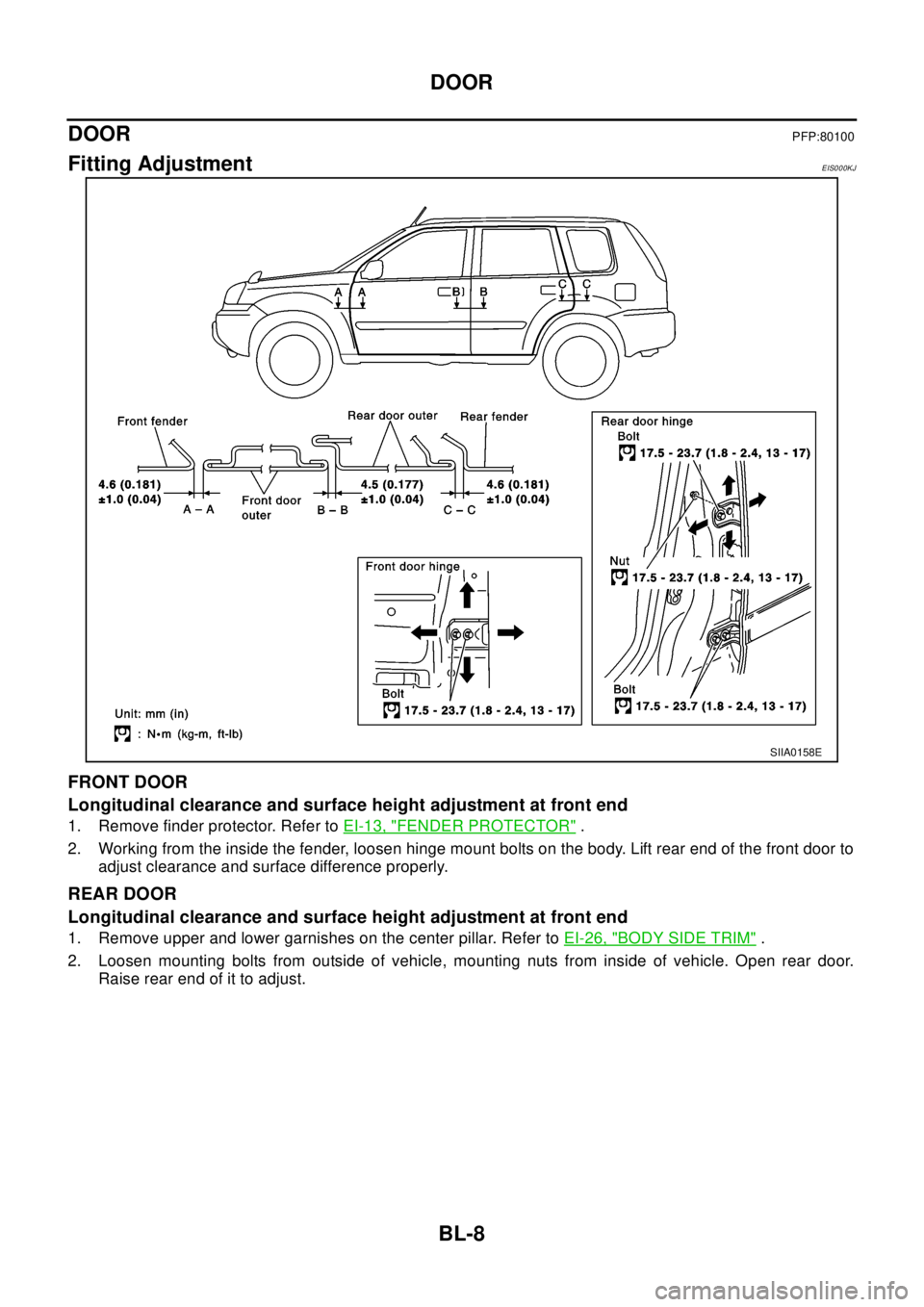
FRONT DOOR
Longitudinal clearance and surface height adjustment at front end
1. Remove finder protector. Refer toEI-13, "FENDER PROTECTOR".
2. Working from the inside the fender, loosen hinge mount bolts on the body. Lift rear end of the front door to
adjust clearance and surface difference properly.
REAR DOOR
Longitudinal clearance and surface height adjustment at front end
1. Remove upper and lower garnishes on the center pillar. Refer toEI-26, "BODY SIDE TRIM".
2. Loosen mounting bolts from outside of vehicle, mounting nuts from inside of vehicle. Open rear door.
Raise rear end of it to adjust.
SIIA0158E
Page 1941 of 3066

EI-1
EXTERIOR & INTERIOR
IBODY
CONTENTS
C
D
E
F
G
H
J
K
L
M
SECTION
A
B
EI
EXTERIOR & INTERIOR
PRECAUTIONS .......................................................... 2
Precautions for Supplemental Restraint System
(SRS) “AIR BAG” and “SEAT BELT PRE-TEN-
SIONER” .................................................................. 2
Precautions .............................................................. 2
CLIP AND FASTENER ............................................... 3
................................................................................. 3
FRONT BUMPER ....................................................... 6
Removal and Installation .......................................... 6
REMOVAL ............................................................. 8
INSTALLATION ..................................................... 8
REAR BUMPER ......................................................... 9
Removal and Installation .......................................... 9
REMOVAL ............................................................. 9
INSTALLATION ................................................... 10
FRONT GRILL ...........................................................11
Removal and Installation .........................................11
REMOVAL ............................................................11
INSTALLATION ....................................................11
COWL TOP ............................................................... 12
Removal and Installation ........................................ 12
REMOVAL ........................................................... 12
INSTALLATION ................................................... 12
FENDER PROTECTOR ............................................ 13
Removal and Installation ........................................ 13
DOOR OUTSIDE MOLDING .................................... 14
Removal and Installation ........................................ 14
REMOVAL ........................................................... 14
INSTALLATION ................................................... 15
SIDE GUARD MOLDING .......................................... 16
Removal and Installation ........................................ 16
DOOR OUTSIDE LOWER MOLDING ...................... 17
Removal and Installation ........................................ 17
SIDE SILL PROTECTOR .......................................... 18
Removal and Installation ........................................ 18ROOF RAIL ............................................................... 19
Removal and Installation ........................................ 19
REMOVAL ........................................................... 19
INSTALLATION ................................................... 20
ROOF SPOILER ....................................................... 21
Removal and Installation ........................................ 21
REMOVAL ........................................................... 21
INSTALLATION ................................................... 21
LICENSE LAMP FINISHER ...................................... 22
Removal and Installation ........................................ 22
REMOVAL ........................................................... 22
INSTALLATION ................................................... 22
DOOR FINISHER ...................................................... 23
Removal and Installation ........................................ 23
FRONT AND REAR ............................................ 23
BACK DOOR TRIM ................................................... 25
Removal and Installation ........................................ 25
BODY SIDE TRIM ..................................................... 26
Removal and Installation ........................................ 26
CENTER PILLAR LOWER GARNISH ................. 27
CENTER PILLAR UPPER GARNISH .................. 27
LUGGAGE SIDE LOWER FINISHER ................. 27
REAR PILLAR FINISHER ................................... 27
DASHBOARD SIDE FINISHER .......................... 27
BODY SIDE WELT .............................................. 27
FLOOR TRIM ............................................................ 28
Removal and Installation ........................................ 28
REMOVAL ........................................................... 28
INSTALLATION ................................................... 28
HEADLINING ............................................................ 29
Removal and Installation ........................................ 29
REMOVAL ........................................................... 29
INSTALLATION ................................................... 30
Page 1966 of 3066
EI-26
BODY SIDE TRIM
BODY SIDE TRIM
PFP:76913
Removal and InstallationEIS000NB
SIIA0217E
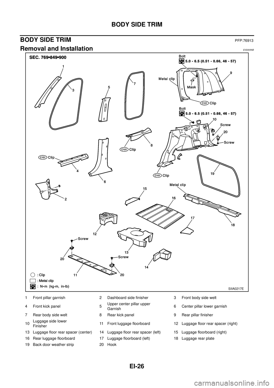
1 Front pillar garnish 2 Dashboard side finisher 3 Front body side welt
4 Front kick panel 5Upper center pillar upper
Garnish6 Center pillar lower garnish
7 Rear body side welt 8 Rear kick panel 9 Rear pillar finisher
10Luggage side lower
Finisher11 Front luggage floorboard 12 Luggage floor rear spacer (right)
13 Luggage floor rear spacer (center) 14 Luggage floor rear spacer (left) 15 Luggage floorboard (right)
16 Rear luggage floorboard 17 Luggage floorboard (left) 18 Luggage rear plate
19 Back door weather strip 20 Hook
Page 1967 of 3066
BODY SIDE TRIM
EI-27
C
D
E
F
G
H
J
K
L
MA
B
EI
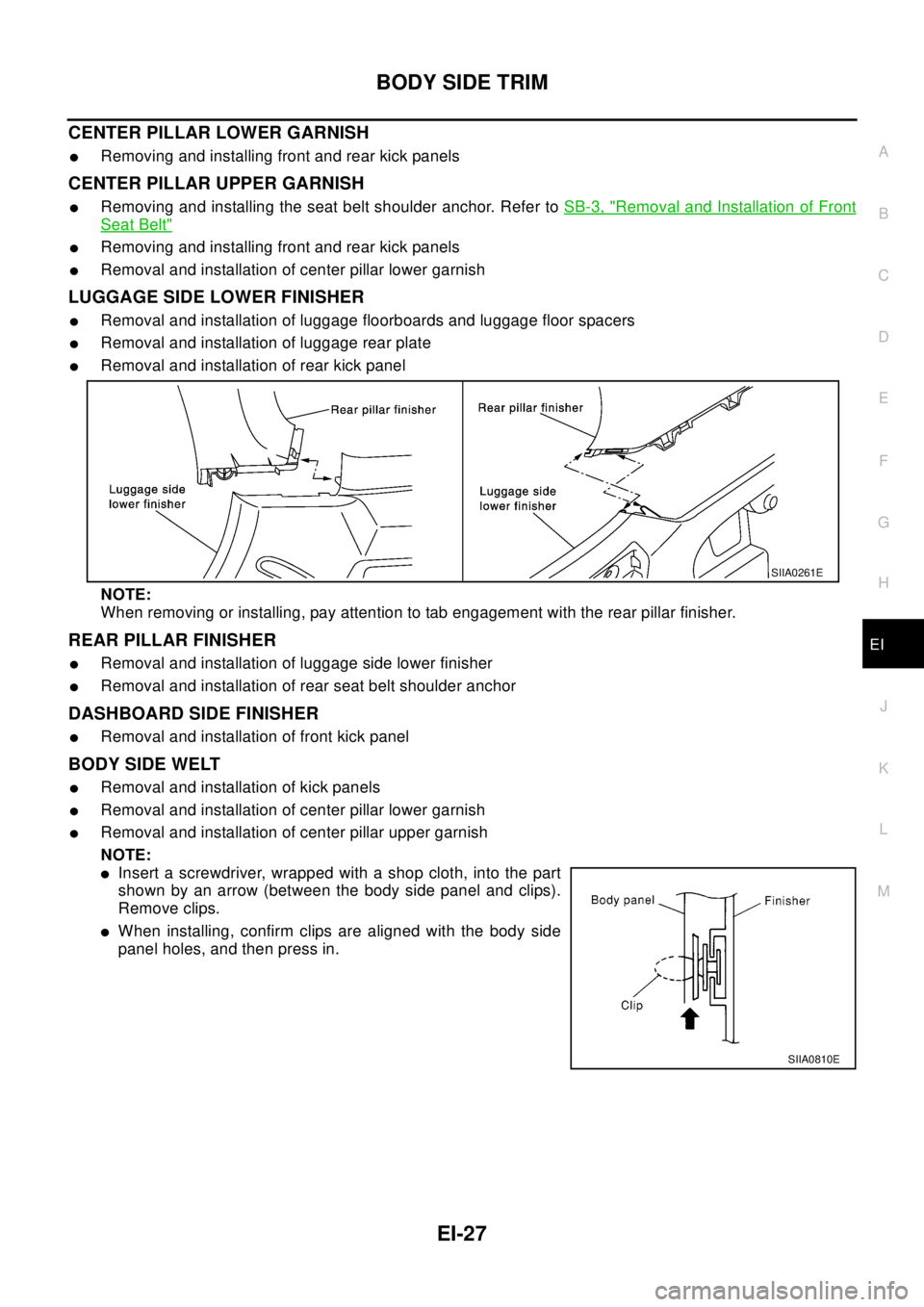
CENTER PILLAR LOWER GARNISH
lRemoving and installing front and rear kick panels
CENTER PILLAR UPPER GARNISH
lRemoving and installing the seat belt shoulder anchor. Refer toSB-3, "Removal and Installation of Front
Seat Belt"
lRemoving and installing front and rear kick panels
lRemoval and installation of center pillar lower garnish
LUGGAGE SIDE LOWER FINISHER
lRemoval and installation of luggage floorboards and luggage floor spacers
lRemoval and installation of luggage rear plate
lRemoval and installation of rear kick panel
NOTE:
When removing or installing, pay attention to tab engagement with the rear pillar finisher.
REAR PILLAR FINISHER
lRemoval and installation of luggage side lower finisher
lRemoval and installation of rear seat belt shoulder anchor
DASHBOARD SIDE FINISHER
lRemoval and installation of front kick panel
BODY SIDE WELT
lRemoval and installation of kick panels
lRemoval and installation of center pillar lower garnish
lRemoval and installation of center pillar upper garnish
NOTE:
lInsert a screwdriver, wrapped with a shop cloth, into the part
shown by an arrow (between the body side panel and clips).
Remove clips.
lWhen installing, confirm clips are aligned with the body side
panel holes, and then press in.
SIIA0261E
SIIA0810E
Page 1968 of 3066
EI-28
FLOOR TRIM
FLOOR TRIM
PFP:74902
Removal and InstallationEIS000NC
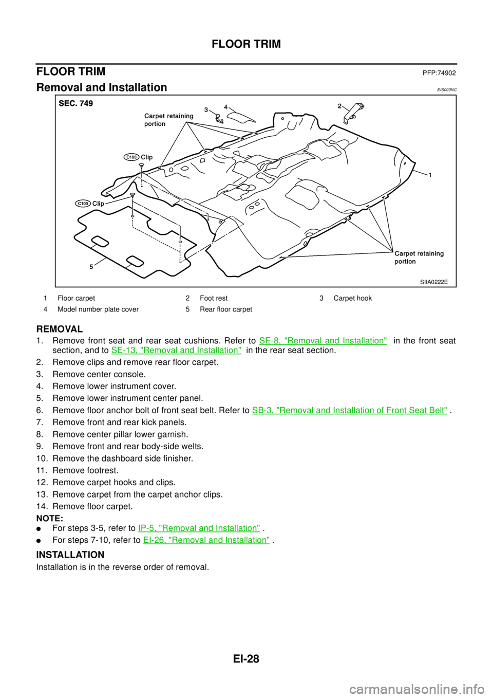
REMOVAL
1. Remove front seat and rear seat cushions. Refer toSE-8, "Removal and Installation"in the front seat
section, and toSE-13, "
Removal and Installation"in the rear seat section.
2. Remove clips and remove rear floor carpet.
3. Remove center console.
4. Remove lower instrument cover.
5. Remove lower instrument center panel.
6. Remove floor anchor bolt of front seat belt. Refer toSB-3, "
Removal and Installation of Front Seat Belt".
7. Remove front and rear kick panels.
8. Remove center pillar lower garnish.
9. Remove front and rear body-side welts.
10. Remove the dashboard side finisher.
11. Remove footrest.
12. Remove carpet hooks and clips.
13. Remove carpet from the carpet anchor clips.
14. Remove floor carpet.
NOTE:
lFor steps 3-5, refer toIP-5, "Removal and Installation".
lFor steps 7-10, refer toEI-26, "Removal and Installation".
INSTALLATION
Installation is in the reverse order of removal.
SIIA0222E
1 Floor carpet 2 Foot rest 3 Carpet hook
4 Model number plate cover 5 Rear floor carpet
Page 1969 of 3066
HEADLINING
EI-29
C
D
E
F
G
H
J
K
L
MA
B
EI
HEADLININGPFP:73910
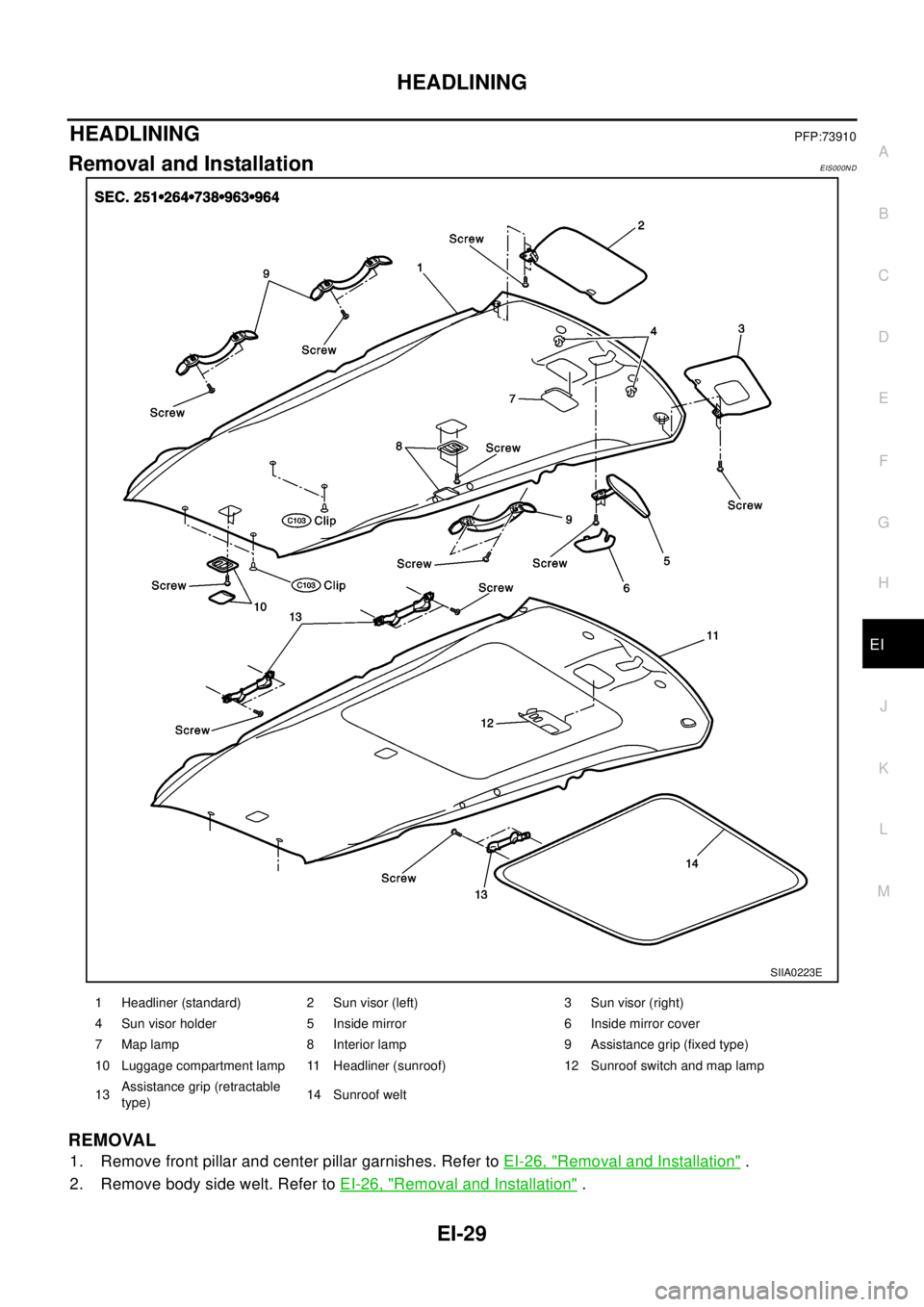
Removal and InstallationEIS000ND
REMOVAL
1. Remove front pillar and center pillar garnishes. Refer toEI-26, "Removal and Installation".
2. Remove body side welt. Refer toEI-26, "
Removal and Installation".
SIIA0223E
1 Headliner (standard) 2 Sun visor (left) 3 Sun visor (right)
4 Sun visor holder 5 Inside mirror 6 Inside mirror cover
7 Map lamp 8 Interior lamp 9 Assistance grip (fixed type)
10 Luggage compartment lamp 11 Headliner (sunroof) 12 Sunroof switch and map lamp
13Assistance grip (retractable
type)14 Sunroof welt
Page 1970 of 3066
EI-30
HEADLINING
3. Remove rear pillar finisher. Refer toEI-26, "Removal and Installation".
4. Remove assistance grip.
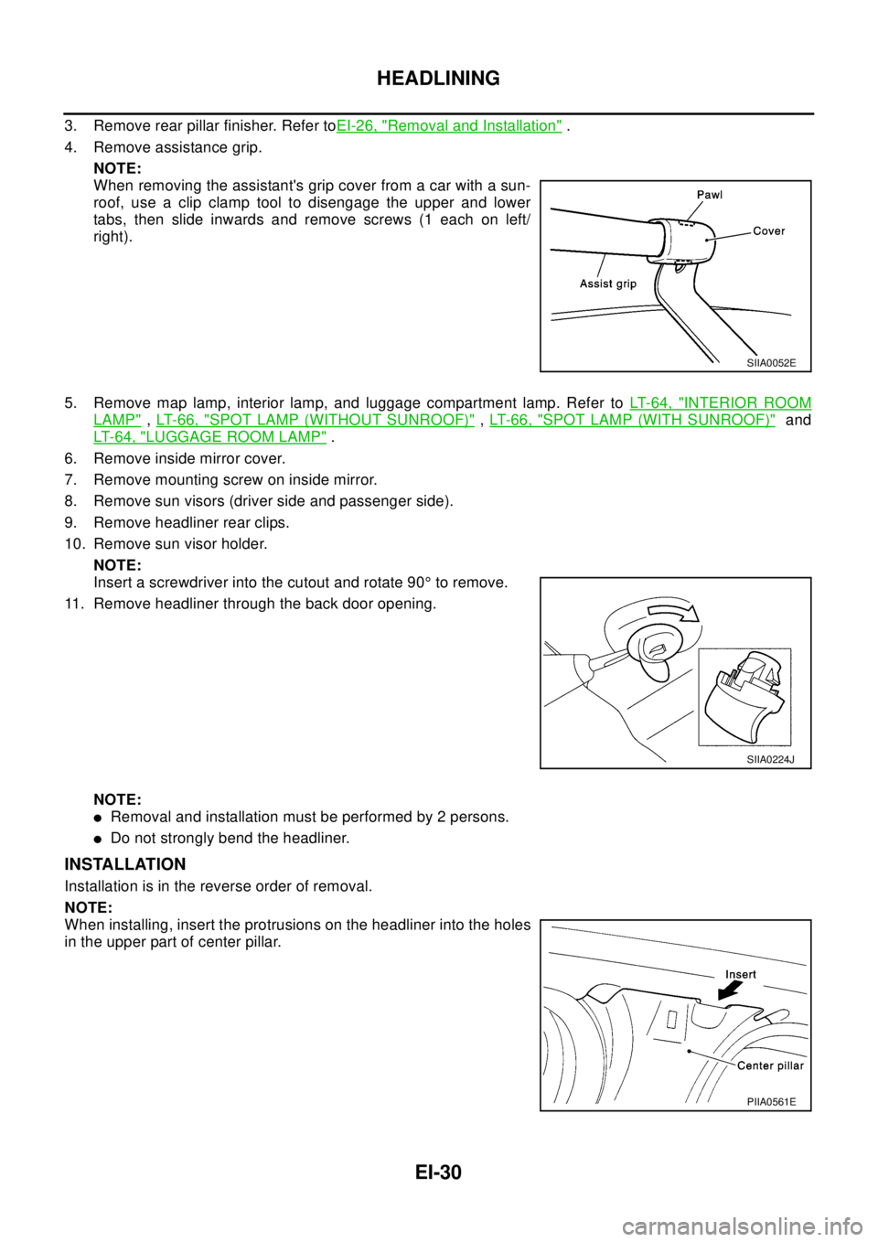
NOTE:
When removing the assistant's grip cover from a car with a sun-
roof, use a clip clamp tool to disengage the upper and lower
tabs, then slide inwards and remove screws (1 each on left/
right).
5. Remove map lamp, interior lamp, and luggage compartment lamp. Refer toLT-64, "
INTERIOR ROOM
LAMP",LT-66, "SPOT LAMP (WITHOUT SUNROOF)",LT- 6 6 , "SPOT LAMP (WITH SUNROOF)"and
LT-64, "
LUGGAGE ROOM LAMP".
6. Remove inside mirror cover.
7. Remove mounting screw on inside mirror.
8. Remove sun visors (driver side and passenger side).
9. Remove headliner rear clips.
10. Remove sun visor holder.
NOTE:
Insert a screwdriver into the cutout and rotate 90°to remove.
11. Remove headliner through the back door opening.
NOTE:
lRemoval and installation must be performed by 2 persons.
lDo not strongly bend the headliner.
INSTALLATION
Installation is in the reverse order of removal.
NOTE:
When installing, insert the protrusions on the headliner into the holes
in the upper part of center pillar.
SIIA0052E
SIIA0224J
PIIA0561E
Page 2306 of 3066
WINDSHIELD GLASS AND MOLDING
GW-3
C
D
E
F
G
H
J
K
L
MA
B
GW
WINDSHIELD GLASS AND MOLDINGPFP:72700
Removal and InstallationEIS001P5
REMOVAL
1. Remove the front pillar garnish and headlining. Refer toEI-26, "BODY SIDE TRIM"andEI-29, "HEAD-
LINING".
2. Remove the weather–strip on the front pillar.
3. Remove the cowl top cover. Refer toEI-12, "
COWL TOP".
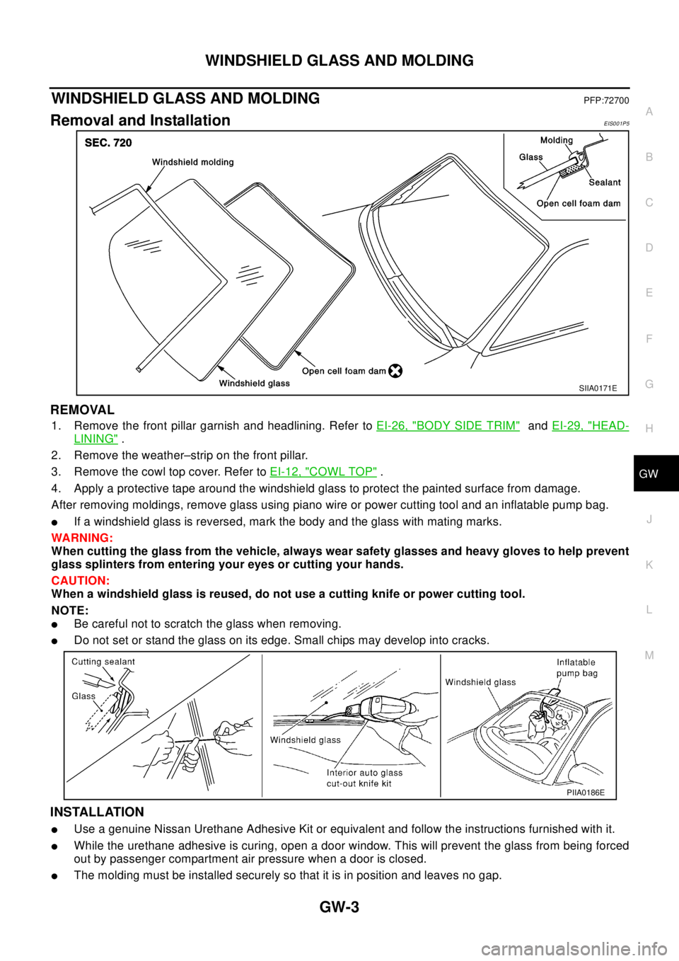
4. Apply a protective tape around the windshield glass to protect the painted surface from damage.
After removing moldings, remove glass using piano wire or power cutting tool and an inflatable pump bag.
lIf a windshield glass is reversed, mark the body and the glass with mating marks.
WA RN ING:
When cutting the glass from the vehicle, always wear safety glasses and heavy gloves to help prevent
glass splinters from entering your eyes or cutting your hands.
CAUTION:
When a windshield glass is reused, do not use a cutting knife or power cutting tool.
NOTE:
lBe careful not to scratch the glass when removing.
lDo not set or stand the glass on its edge. Small chips may develop into cracks.
INSTALLATION
lUse a genuine Nissan Urethane Adhesive Kit or equivalent and follow the instructions furnished with it.
lWhile the urethane adhesive is curing, open a door window. This will prevent the glass from being forced
out by passenger compartment air pressure when a door is closed.
lThe molding must be installed securely so that it is in position and leaves no gap.
SIIA0171E
PIIA0186E
Page 2308 of 3066
SIDE WINDOW GLASS
GW-5
C
D
E
F
G
H
J
K
L
MA
B
GW
SIDE WINDOW GLASSPFP:83300
Removal and InstallationEIS000LV
REMOVAL
1. Remove luggage side lower finisher and rear pillar finisher. Refer toEI-26, "BODY SIDE TRIM".
2. Apply protective tape on body panels around side window glass to protect painted surfaces from damage.
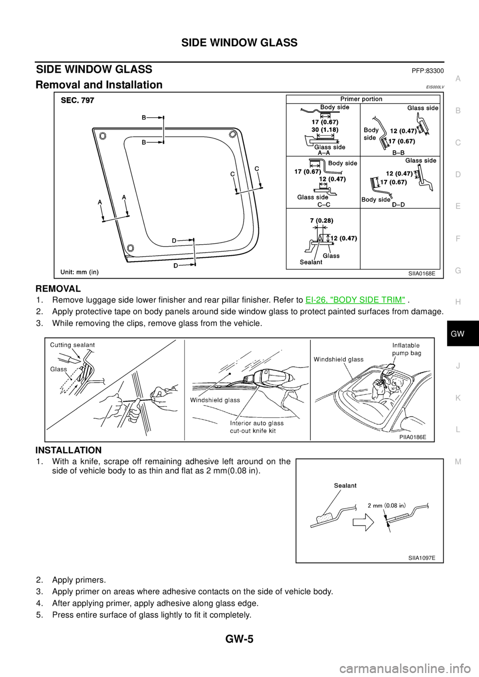
3. While removing the clips, remove glass from the vehicle.
INSTALLATION
1. With a knife, scrape off remaining adhesive left around on the
side of vehicle body to as thin and flat as 2 mm(0.08 in).
2. Apply primers.
3. Apply primer on areas where adhesive contacts on the side of vehicle body.
4. After applying primer, apply adhesive along glass edge.
5. Press entire surface of glass lightly to fit it completely.
SIIA0168E
PIIA0186E
SIIA1097E
Page 2367 of 3066

IP-1
INSTRUMENT PANEL
IBODY
CONTENTS
C
D
E
F
G
H
J
K
L
M
SECTION
A
B
IP
INSTRUMENT PANEL
PRECAUTIONS .......................................................... 2
Precautions for Supplemental Restraint System
(SRS) “AIR BAG” and “SEAT BELT PRE-TEN-
SIONER” .................................................................. 2
Precautions .............................................................. 2
INSTRUMENT PANEL ASSEMBLY ........................... 3
Component Parts Drawing ....................................... 3
Removal and Installation .......................................... 5
TABLE OF WORK ITEM ....................................... 5
FRONT SPEAKER GRILLE .................................. 6
INSTRUMENT FINISHER ..................................... 6
CUP HOLDER ....................................................... 6
CLUSTER LID A ................................................... 6
COMBINATION METER ....................................... 6
GPS ANTENNA .................................................... 6
POCKET ............................................................... 6
STEERING COLUMN COVER ............................. 6
INSTRUMENT LOWER DRIVER PANEL ............. 7
MIRROR CONTROL SWITCH .............................. 7CLUSTER LID C ................................................... 7
AUDIO UNIT AND POCKET ................................. 7
CLUSTER LID FINISHER ..................................... 7
A/T OR M/T FINISHER ......................................... 8
CENTER CONSOLE ............................................. 8
CD AUTO–CHANGER AND POCKET .................. 8
HEATER CONTROL FINISHER ............................ 8
HEATER CONTROLLER ....................................... 8
LOWER INSTRUMENT COVER ........................... 8
INSTRUMENT LOWER CENTER PANEL ............ 8
GLOVE BOX ......................................................... 9
LOWER INSTRUMENT PANEL ............................ 9
GLOVE BOX COVER ............................................ 9
FRONT PASSENGER AIR BAG MODULE ........... 9
INSTRUMENT MASK ............................................ 9
FRONT PILLAR GARNISH ................................... 9
INSTRUMENT PANEL .......................................... 9
Disassembly and Assembly .................................... 10
CONSOLE BOX ASSEMBLY .............................. 10