ECO mode OPEL FRONTERA 1998 Workshop Manual
[x] Cancel search | Manufacturer: OPEL, Model Year: 1998, Model line: FRONTERA, Model: OPEL FRONTERA 1998Pages: 6000, PDF Size: 97 MB
Page 215 of 6000
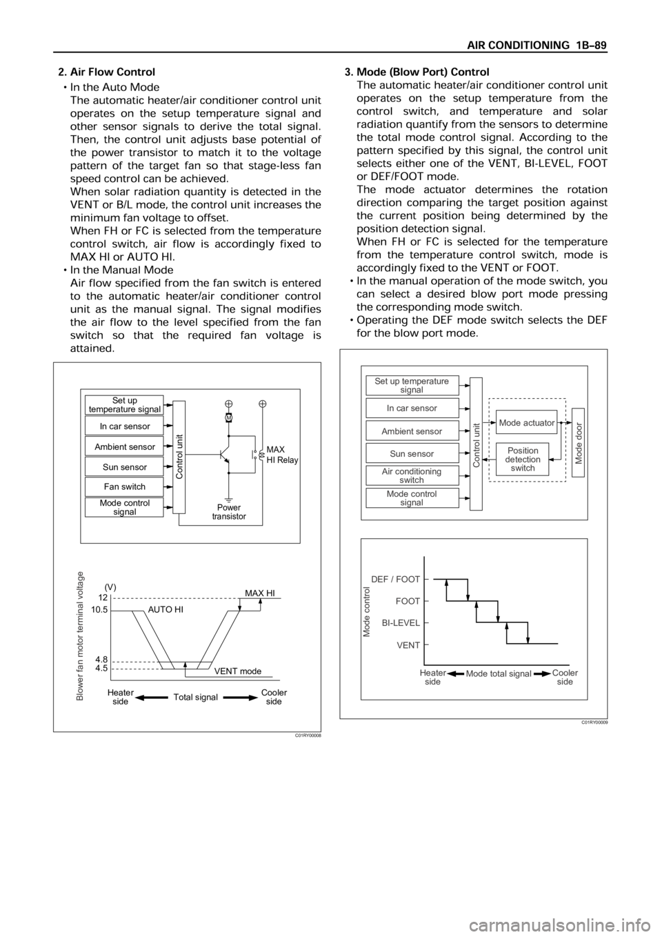
4.512
(V)
M
MAX
HI Relay
Power
transistor
4.8 10.5MAX HI Set up
temperature signal
Control unit
In car sensor
Ambient sensor
Sun sensor
Mode control
signal Fan switch
AUTO HI
Heater
sideCooler
side Total signalVENT mode
Blower fan motor terminal voltage
C01RY00008
Mode control
DEF / FOOTSet up temperature
signal
Mode actuator
Mode doorPosition
detection
switch
Control unit
In car sensor
Sun sensor
Air conditioning
switch
Mode control
signal Ambient sensor
FOOT
BI-LEVEL
VENT
Heater
sideCooler
side Mode total signal
C01RY00009
Page 216 of 6000
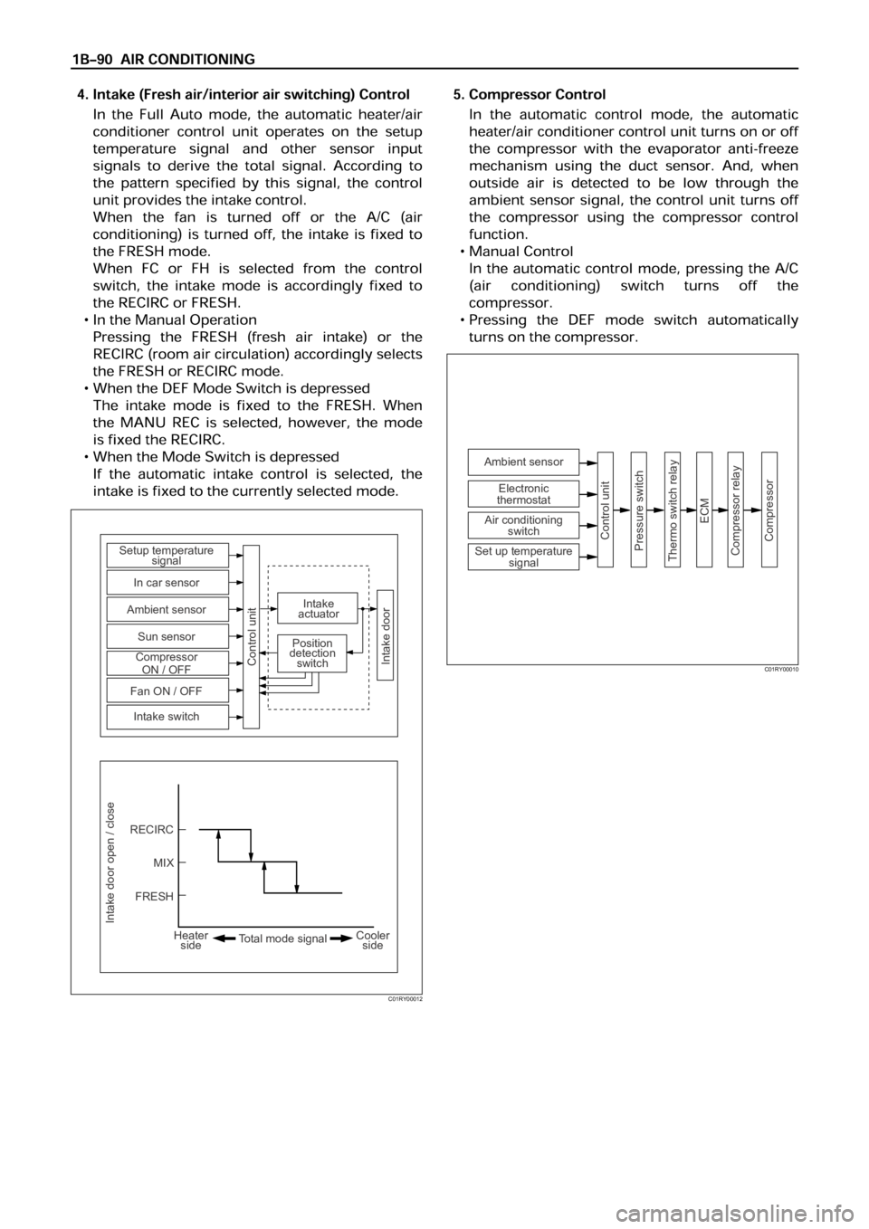
Intake door open / close
RECIRC Setup temperature
signal
Intake
actuator
Position
detection
switch
In car sensor
Ambient sensor
Sun sensor
Compressor
ON / OFF
Fan ON / OFF
Intake switch
Control unit
Intake door
MIX
FRESH
Heater
sideCooler
side Total mode signal
C01RY00012
Ambient sensor
Control unit
Pressure switch
Thermo switch relay
ECM
Compressor relay
Compressor
Electronic
thermostat
Air conditioning
switch
Set up temperature
signal
C01RY00010
Page 224 of 6000

LED on
LED off Indication for presence
of a troubleIndication for normal state
0.5 0.5 0.5
3 seconds interval
ON
OFF
Display pattern Failed part
Normal pattern
In car sensor
Ambient sensor
Sun sensor (Note 1)
Duct sensor
Temperature control lever (Note 2)
Fan switch (Note 3)
Mix actuator
Mode (blow port) control
Intake (fresh air/interior air switching) control
F01RX010
F01RY00008
Page 225 of 6000

LED on
LED off Indication for presence of a trouble Indication for normal state
0.5 0.5 0.5
3 second interval
Display pattern
ON
OFFNormal pattern
In car sensor
Ambient sensor
Sun sensor
Duct sensor
Mix actuatorFailed part
F01RX011
F01RY00007
FAN
MIX
MODE
DOOR
INTAKE
DOOR
SET UP
TEMPERATURE
100
(%)
33.5
F/H
VENT
B/L
FOOT
D/F
DEF
REC
MIX
FRE
F/C2021222324252627282930F/H (%)
F/C
F01RY00001
Page 544 of 6000
4B1–11 DRIVE LINE CONTROL SYSTEM (SHIFT ON THE FLY)
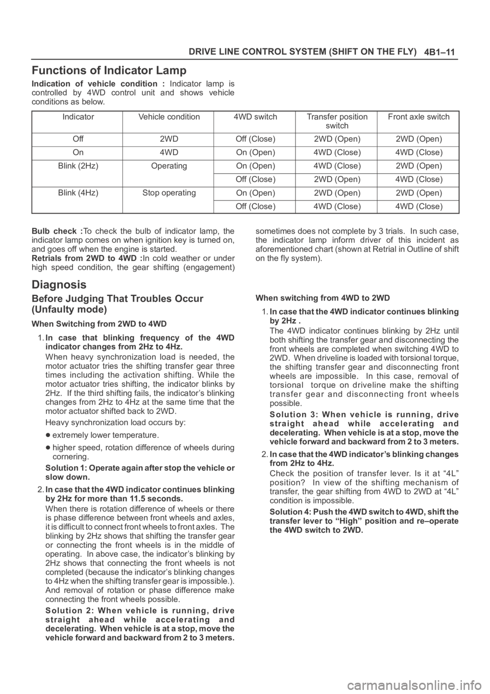
Functions of Indicator Lamp
Indication of vehicle condition : Indicator lamp is
controlled by 4WD control unit and shows vehicle
conditions as below.
Indicator
Vehicle condition4WD switchTransfer position
switchFront axle switch
Off2WDOff (Close)2WD (Open)2WD (Open)
On4WDOn (Open)4WD (Close)4WD (Close)
Blink (2Hz)OperatingOn (Open)4WD (Close)2WD (Open)
Off (Close)2WD (Open)4WD (Close)
Blink (4Hz)Stop operatingOn (Open)2WD (Open)2WD (Open)
Off (Close)4WD (Close)4WD (Close)
Bulb check :To check the bulb of indicator lamp, the
indicator lamp comes on when ignition key is turned on,
and goes off when the engine is started.
Retrials from 2WD to 4WD :In cold weather or under
high speed condition, the gear shifting (engagement)sometimes does not complete by 3 trials. In such case,
the indicator lamp inform driver of this incident as
aforementioned chart (shown at Retrial in Outline of shift
on the fly system).
Diagnosis
Before Judging That Troubles Occur
(Unfaulty mode)
When Switching from 2WD to 4WD
1.In case that blinking frequency of the 4WD
indicator changes from 2Hz to 4Hz.
When heavy synchronization load is needed, the
motor actuator tries the shifting transfer gear three
times including the activation shifting. While the
motor actuator tries shifting, the indicator blinks by
2Hz. If the third shifting fails, the indicator’s blinking
changes from 2Hz to 4Hz at the same time that the
motor actuator shifted back to 2WD.
Heavy synchronization load occurs by:
extremely lower temperature.
higher speed, rotation difference of wheels during
cornering.
Solution 1: Operate again after stop the vehicle or
slow down.
2.In case that the 4WD indicator continues blinking
by 2Hz for more than 11.5 seconds.
When there is rotation difference of wheels or there
is phase difference between front wheels and axles,
it is difficult to connect front wheels to front axles. The
blinking by 2Hz shows that shifting the transfer gear
or connecting the front wheels is in the middle of
operating. In above case, the indicator’s blinking by
2Hz shows that connecting the front wheels is not
completed (because the indicator’s blinking changes
to 4Hz when the shifting transfer gear is impossible.).
And removal of rotation or phase difference make
connecting the front wheels possible.
Solution 2: When vehicle is running, drive
straight ahead while accelerating and
decelerating. When vehicle is at a stop, move the
vehicle forward and backward from 2 to 3 meters.When switching from 4WD to 2WD
1.In case that the 4WD indicator continues blinking
by 2Hz .
The 4WD indicator continues blinking by 2Hz until
both shifting the transfer gear and disconnecting the
front wheels are completed when switching 4WD to
2WD. When driveline is loaded with torsional torque,
the shifting transfer gear and disconnecting front
wheels are impossible. In this case, removal of
torsional torque on driveline make the shifting
transfer gear and disconnecting front wheels
possible.
Solution 3: When vehicle is running, drive
straight ahead while accelerating and
decelerating. When vehicle is at a stop, move the
vehicle forward and backward from 2 to 3 meters.
2.In case that the 4WD indicator’s blinking changes
from 2Hz to 4Hz.
Check the position of transfer lever. Is it at “4L”
position? In view of the shifting mechanism of
transfer, the gear shifting from 4WD to 2WD at “4L”
condition is impossible.
Solution 4: Push the 4WD switch to 4WD, shift the
transfer lever to “High” position and re–operate
the 4WD switch to 2WD.
Page 574 of 6000
4B2–3 DRIVE LINE CONTROL SYSTEM (TOD)
detects the slip condition, determines the optimum torque
based on the feedback control logic, and increases the
torque to the front wheels.
The control unit uses the signal from the throttle position
sensor to predict the future vehicle condition and the
intention of the driver with respect to acceleration and
deceleration, and determines the initial torque distribution
using these data and the information from the speed
sensors.
In case of small circle turning in the parking lot, for
example, the control unit minimizes the clutch pressing
force restrict a braking phenomenon. When the ABS
becomes active, the control unit optimizes the clutch
pressing force to ensure stable braking.
TOD Indicator Control
The TOD indicator on the instrument panel informs the
driver of the current working status of the transfer unit.
The information consists of two items: the drive mode
(2H, TOD, 4L, transition) and the torque split status of the
TOD (torque distribution level). The indicator can display
occasional errors and corresponding error codes.
Page 582 of 6000
4B2–11 DRIVE LINE CONTROL SYSTEM (TOD)
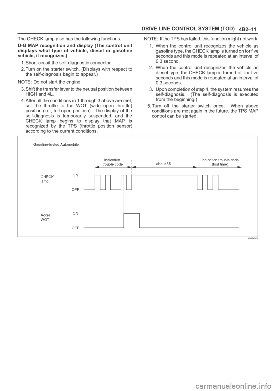
The CHECK lamp also has the following functions.
D-G MAP recognition and display (The control unit
displays what type of vehicle, diesel or gasoline
vehicle, it recognizes.)
1. Short-circuit the self-diagnostic connector.
2. Turn on the starter switch. (Displays with respect to
the self-diagnosis begin to appear.)
NOTE: Do not start the engine.
3. Shift the transfer lever to the neutral position between
HIGH and 4L.
4. After all the conditions in 1 through 3 above are met,
set the throttle to the WOT (wide open throttle)
position (i.e., full open position). The display of the
self-diagnosis is temporarily suspended, and the
CHECK lamp begins to display that MAP is
recognized by the TPS (throttle position sensor)
according to the current conditions.NOTE: If the TPS has failed, this function might not work.
1. When the control unit recognizes the vehicle as
gasoline type, the CHECK lamp is turned on for five
seconds and this mode is repeated at an interval of
0.3 second.
2. When the control unit recognizes the vehicle as
diesel type, the CHECK lamp is turned off for five
seconds and this mode is repeated at an interval of
0.3 seconds.
3. Upon completion of step 4, the system resumes the
self-diagnosis. (The self-diagnosis is executed
from the beginning.)
5. Turn off the starter switch once. When above
conditions are met again in the future, the TPS MAP
control can be started.
C04RW010
Page 585 of 6000
DRIVE LINE CONTROL SYSTEM (TOD) 4B2–14
How to Clear The Trouble Code
The trouble codes saved to the control unit can be deleted
by the following procedure if the starter switch is being in
the OFF position.
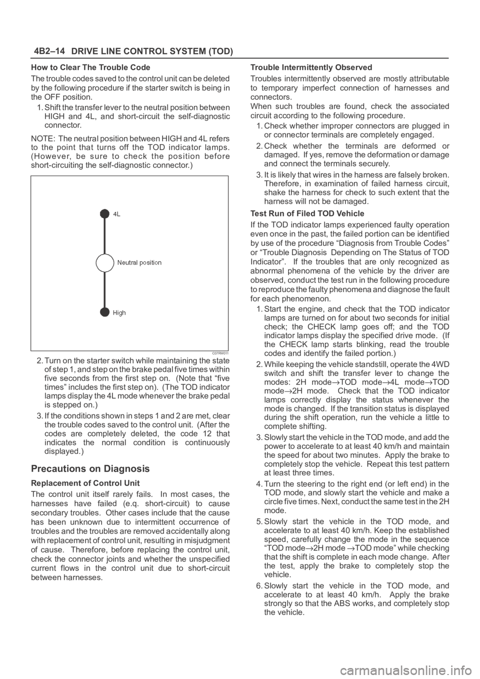
1. Shift the transfer lever to the neutral position between
HIGH and 4L, and short-circuit the self-diagnostic
connector.
NOTE: The neutral position between HIGH and 4L refers
to the point that turns off the TOD indicator lamps.
(However, be sure to check the position before
short-circuiting the self-diagnostic connector.)
C07RW011
2. Turn on the starter switch while maintaining the state
of step 1, and step on the brake pedal five times within
five seconds from the first step on. (Note that “five
times” includes the first step on). (The TOD indicator
lamps display the 4L mode whenever the brake pedal
is stepped on.)
3. If the conditions shown in steps 1 and 2 are met, clear
the trouble codes saved to the control unit. (After the
codes are completely deleted, the code 12 that
indicates the normal condition is continuously
displayed.)
Precautions on Diagnosis
Replacement of Control Unit
The control unit itself rarely fails. In most cases, the
harnesses have failed (e.q. short-circuit) to cause
secondary troubles. Other cases include that the cause
has been unknown due to intermittent occurrence of
troubles and the troubles are removed accidentally along
with replacement of control unit, resulting in misjudgment
of cause. Therefore, before replacing the control unit,
check the connector joints and whether the unspecified
current flows in the control unit due to short-circuit
between harnesses.Trouble Intermittently Observed
Troubles intermittently observed are mostly attributable
to temporary imperfect connection of harnesses and
connectors.
When such troubles are found, check the associated
circuit according to the following procedure.
1. Check whether improper connectors are plugged in
or connector terminals are completely engaged.
2. Check whether the terminals are deformed or
damaged. If yes, remove the deformation or damage
and connect the terminals securely.
3. It is likely that wires in the harness are falsely broken.
Therefore, in examination of failed harness circuit,
shake the harness for check to such extent that the
harness will not be damaged.
Test Run of Filed TOD Vehicle
If the TOD indicator lamps experienced faulty operation
even once in the past, the failed portion can be identified
by use of the procedure “Diagnosis from Trouble Codes”
or “Trouble Diagnosis Depending on The Status of TOD
Indicator”. If the troubles that are only recognized as
abnormal phenomena of the vehicle by the driver are
observed, conduct the test run in the following procedure
to reproduce the faulty phenomena and diagnose the fault
for each phenomenon.
1. Start the engine, and check that the TOD indicator
lamps are turned on for about two seconds for initial
check; the CHECK lamp goes off; and the TOD
indicator lamps display the specified drive mode. (If
the CHECK lamp starts blinking, read the trouble
codes and identify the failed portion.)
2. While keeping the vehicle standstill, operate the 4WD
switch and shift the transfer lever to change the
modes: 2H mode
TOD mode4L modeTOD
mode
2H mode. Check that the TOD indicator
lamps correctly display the status whenever the
mode is changed. If the transition status is displayed
during the shift operation, run the vehicle a little to
complete shifting.
3. Slowly start the vehicle in the TOD mode, and add the
power to accelerate to at least 40 km/h and maintain
the speed for about two minutes. Apply the brake to
completely stop the vehicle. Repeat this test pattern
at least three times.
4. Turn the steering to the right end (or left end) in the
TOD mode, and slowly start the vehicle and make a
c i r c l e f i v e t i m e s . N e x t , c o n d u c t t h e s a m e t e s t i n t h e 2 H
mode.
5. Slowly start the vehicle in the TOD mode, and
accelerate to at least 40 km/h. Keep the established
speed, carefully change the mode in the sequence
“TOD mode
2H mode TOD mode” while checking
that the shift is complete in each mode change. After
the test, apply the brake to completely stop the
vehicle.
6. Slowly start the vehicle in the TOD mode, and
accelerate to at least 40 km/h. Apply the brake
strongly so that the ABS works, and completely stop
the vehicle.
Page 625 of 6000
DRIVE LINE CONTROL SYSTEM (TOD) 4B2–54
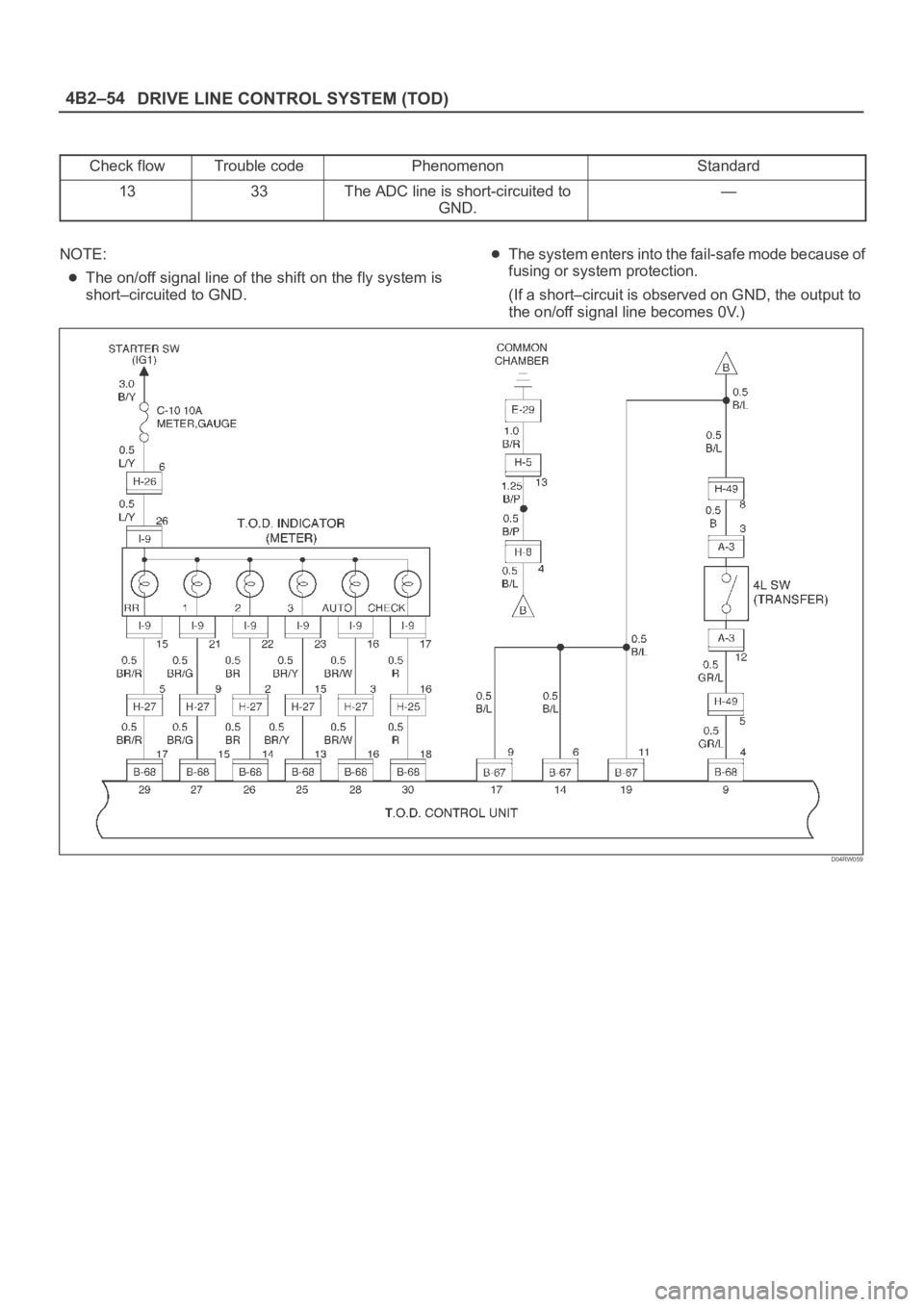
Check flowTrouble codePhenomenonStandard
1333The ADC line is short-circuited to
GND.—
NOTE:
The on/off signal line of the shift on the fly system is
short–circuited to GND.
The system enters into the fail-safe mode because of
fusing or system protection.
(If a short–circuit is observed on GND, the output to
the on/off signal line becomes 0V.)
D04RW059
Page 648 of 6000
4B2–77 DRIVE LINE CONTROL SYSTEM (TOD)
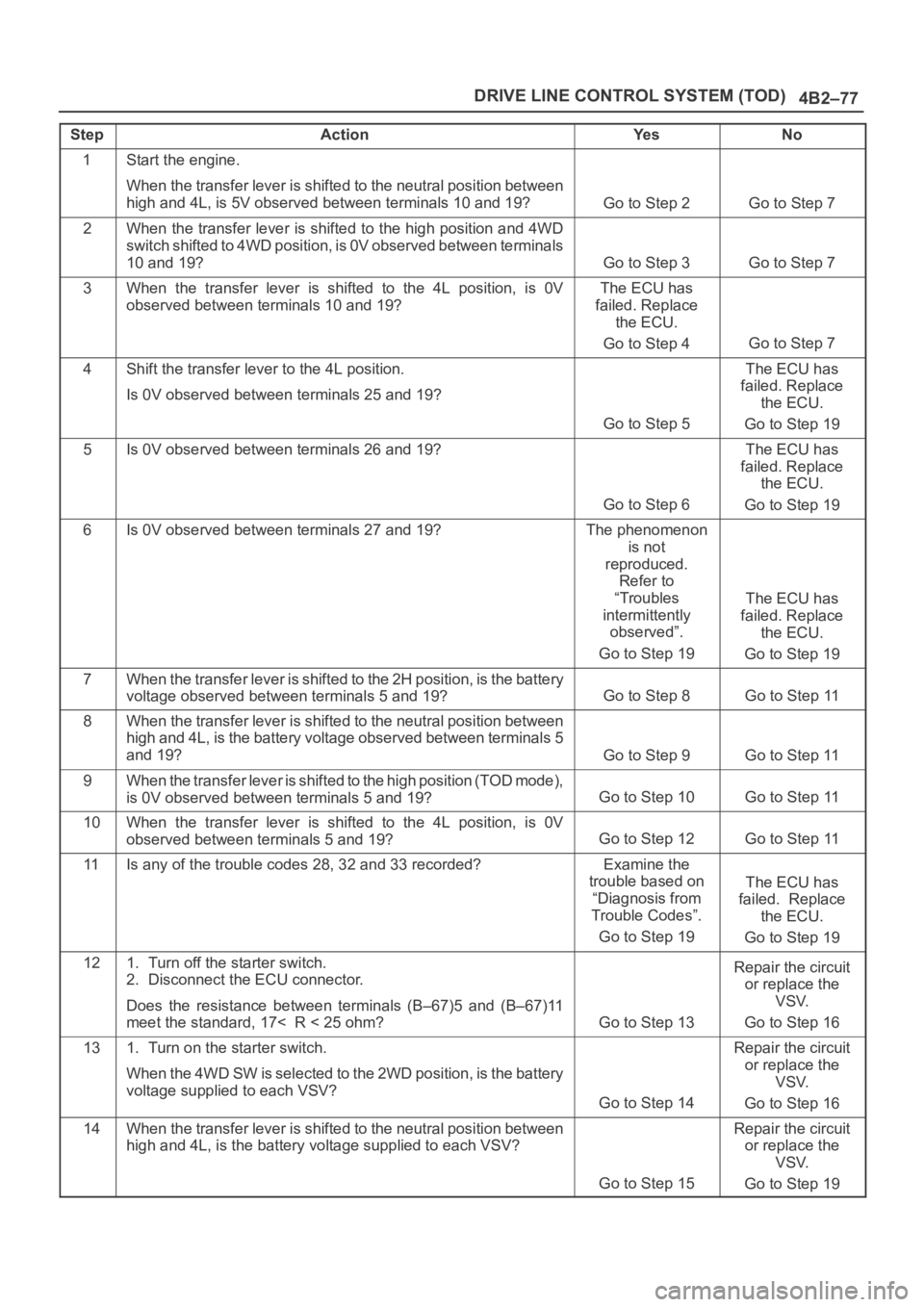
StepActionYe sNo
1Start the engine.
When the transfer lever is shifted to the neutral position between
high and 4L, is 5V observed between terminals 10 and 19?
Go to Step 2Go to Step 7
2When the transfer lever is shifted to the high position and 4WD
switch shifted to 4WD position, is 0V observed between terminals
10 and 19?
Go to Step 3Go to Step 7
3When the transfer lever is shifted to the 4L position, is 0V
observed between terminals 10 and 19?The ECU has
failed. Replace
the ECU.
Go to Step 4
Go to Step 7
4Shift the transfer lever to the 4L position.
Is 0V observed between terminals 25 and 19?
Go to Step 5
The ECU has
failed. Replace
the ECU.
Go to Step 19
5Is 0V observed between terminals 26 and 19?
Go to Step 6
The ECU has
failed. Replace
the ECU.
Go to Step 19
6Is 0V observed between terminals 27 and 19?The phenomenon
is not
reproduced.
Refer to
“Troubles
intermittently
observed”.
Go to Step 19
The ECU has
failed. Replace
the ECU.
Go to Step 19
7When the transfer lever is shifted to the 2H position, is the battery
voltage observed between terminals 5 and 19?
Go to Step 8Go to Step 11
8When the transfer lever is shifted to the neutral position between
high and 4L, is the battery voltage observed between terminals 5
and 19?
Go to Step 9Go to Step 11
9When the transfer lever is shifted to the high position (TOD mode),
is 0V observed between terminals 5 and 19?
Go to Step 10Go to Step 11
10When the transfer lever is shifted to the 4L position, is 0V
observed between terminals 5 and 19?
Go to Step 12Go to Step 11
11Is any of the trouble codes 28, 32 and 33 recorded?Examine the
trouble based on
“Diagnosis from
Trouble Codes”.
Go to Step 19
The ECU has
failed. Replace
the ECU.
Go to Step 19
121. Turn off the starter switch.
2. Disconnect the ECU connector.
Does the resistance between terminals (B–67)5 and (B–67)11
meet the standard, 17< R < 25 ohm?
Go to Step 13
Repair the circuit
or replace the
VSV.
Go to Step 16
131. Turn on the starter switch.
When the 4WD SW is selected to the 2WD position, is the battery
voltage supplied to each VSV?
Go to Step 14
Repair the circuit
or replace the
VSV.
Go to Step 16
14When the transfer lever is shifted to the neutral position between
high and 4L, is the battery voltage supplied to each VSV?
Go to Step 15
Repair the circuit
or replace the
VSV.
Go to Step 19