battery location OPEL FRONTERA 1998 Workshop Manual
[x] Cancel search | Manufacturer: OPEL, Model Year: 1998, Model line: FRONTERA, Model: OPEL FRONTERA 1998Pages: 6000, PDF Size: 97 MB
Page 588 of 6000
4B2–17 DRIVE LINE CONTROL SYSTEM (TOD)
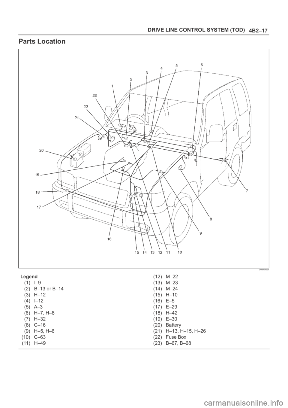
Parts Location
D08RW621
Legend
(1) I–9
(2) B–13 or B–14
(3) H–12
(4) I–12
(5) A–3
(6) H–7, H–8
(7) H–32
(8) C–16
(9) H–5, H–6
(10) C–63
(11) H–49(12) M–22
(13) M–23
(14) M–24
(15) H–10
(16) E–5
(17) E–29
(18) H–42
(19) E–30
(20) Battery
(21) H–13, H–15, H–26
(22) Fuse Box
(23) B–67, B–68
Page 959 of 6000
6A–3
ENGINE MECHANICAL
General Description
Engine Cleanliness And Care
An automobile engine is a combination of many
machined, honed, polished and lapped surfaces with
tolerances that are measured in the thousandths of a
millimeter (ten thousandths of an inch). Accordingly,
when any internal engine parts are serviced, care and
cleanliness are important. Throughout this section, it
should be understood that proper cleaning and protection
of machined surfaces and friction areas is part of the
repair procedure. This is considered standard shop
practice even if not specifically stated.
A liberal coating of engine oil should be applied to all
friction areas during assembly to protect and lubricate
the surfaces on initial operation.
Whenever valve train components, pistons, piston
rings, connecting rods, rod bearings, and crankshaft
journal bearings are removed for service, they should
be retained in order.
At the time of installation, they should be installed in
the same locations and with the same mating
surfaces as when removed.
Battery cables should be disconnected before any
major work is performed on the engine. Failure to
disconnect cables may result in damage to wire
harness or other electrical parts.
The six cylinders of this engine are identified by
numbers; Right side cylinders 1, 3 and 5, Left side
cylinders 2, 4 and 6, as counted from crankshaft
pulley side to flywheel side.
General Information on Engine Service
The following information on engine service should be
noted carefully, as it is important in preventing damage
and contributing to reliable engine performance:
When raising or supporting the engine for any reason,
do not use a jack under the oil pan. Due to the small
clearance between the oil pan and the oil pump
strainer, jacking against the oil pan may cause
damage to the oil pick–up unit.
The 12–volt electrical system is capable of damaging
circuits. When performing any work where electrical
terminals could possibly be grounded, the ground
cable of the battery should be disconnected at the
battery.
Any time the intake air duct or air cleaner is removed,
the intake opening should be covered. This will
protect against accidental entrance of foreign
material into the cylinder which could cause extensive
damage when the engine is started.
Cylinder Block
The cylinder block is made of aluminum die–cast casting
for 75
V–type six cylinders. It has a rear plate integrated
structure and employs a deep skint. The cylinder liner is
cast and the liner inner diameter and crankshaft journal
diameter are classified into grades. The crankshaft is
supported by four bearings of which width of No.3 bearing
on the body side is different in order to support the thrust
bearing. The bearing cap is made of nodular cast iron and
each bearing cap uses four bolts and two side bolts.
Cylinder Head
The cylinder head, made of aluminum alloy casting
employs a pent–roof type combustion chamber with a
spark plug in the center. The intake and exhaust valves
are placed in V–type design. The ports are cross–flow
type.
Va l v e Tr a i n
Intake and exhaust camshaft on the both side of banks
are driven through an camshaft drive gear by timing belt.
The valves are operated by the camshaft and the valve
clearance is adjusted to select suitable thickness shim.
Intake Manifold
The intake manifold system is composed of the aluminum
cast common chamber and intake manifold attached with
six fuel injectors.
Exhaust Manifold
The exhaust manifold is made of nodular cast iron.
Pistons and Connecting Rods
Aluminum pistons are used after selecting the grade that
meets the cylinder bore diameter. Each piston has two
compression rings and one oil ring. The piston pin is made
of chromium steel is offset 1mm toward the thrust side,
and the thrust pressure of piston to the cylinder wall varies
gradually as the piston travels. The connecting rods are
made of forged steel. The connecting rod bearings are
graded for correct seze selection.
Crankshaft and Bearings
The crankshaft is made of Ductile cast–iron. Pins and
journals are graded for correct size selection for their
bearing.
Engine Lubrication
The oil discharged by a trochoid–type oil pump driven by
the crankshaft is fed through full–flow oil filter and to the oil
gallery provided under the crankshaft bearing cap. The oil
is then led to the crankshaft journals and cylinder head.
The crank pins are lubricated with oil from crankshaft
journals through oil holes. Also, an oil jet is fed to each
cylinder from crankshaft juornals on the connecting rod
for piston cleaning. The oil pan flange is dealed with liquid
packing only; do not deform or damage the flange surface
during removal or installation.
Page 1080 of 6000
ENGINE ELECTRICAL6D1–1
ENGINE
ENGINE ELECTRICAL
CONTENTS
Service Precaution 6D1–1. . . . . . . . . . . . . . . . . . . . . .
Battery 6D1–2. . . . . . . . . . . . . . . . . . . . . . . . . . . . . . . . .
General Description 6D1–2. . . . . . . . . . . . . . . . . . . .
Diagnosis 6D1–2. . . . . . . . . . . . . . . . . . . . . . . . . . . . .
Battery Charging 6D1–3. . . . . . . . . . . . . . . . . . . . . . Jump Starting 6D1–3. . . . . . . . . . . . . . . . . . . . . . . . .
Battery Removal 6D1–4. . . . . . . . . . . . . . . . . . . . . .
Battery Installation 6D1–4. . . . . . . . . . . . . . . . . . . . .
Main Data and Specifications 6D1–5. . . . . . . . . . .
Service Precaution
WARNING: IF SO EQUIPPED WITH A
SUPPLEMENTAL RESTRAINT SYSTEM (SRS),
REFER TO THE SRS COMPONENT AND WIRING
LOCATION VIEW IN ORDER TO DETERMINE
WHETHER YOU ARE PERFORMING SERVICE ON OR
NEAR THE SRS COMPONENTS OR THE SRS
WIRING. WHEN YOU ARE PERFORMING SERVICE
ON OR NEAR THE SRS COMPONENTS OR THE SRS
WIRING, REFER TO THE SRS SERVICE
INFORMATION. FAILURE TO FOLLOW WARNINGS
COULD RESULT IN POSSIBLE AIR BAG
DEPLOYMENT, PERSONAL INJURY, OR
OTHERWISE UNNEEDED SRS SYSTEM REPAIRS.
CAUTION: Always use the correct fastener in the
proper location. When you replace a fastener, use
ONLY the exact part number for that application.
ISUZU will call out those fasteners that require a
replacement after removal. ISUZU will also call out
the fasteners that require thread lockers or thread
sealant. UNLESS OTHERWISE SPECIFIED, do not
use supplemental coatings (Paints, greases, or other
corrosion inhibitors) on threaded fasteners or
fastener joint interfaces. Generally, such coatings
adversely affect the fastener torque and the joint
clamping force, and may damage the fastener. When
you install fasteners, use the correct tightening
sequence and specifications. Following these
instructions can help you avoid damage to parts and
systems.
Page 1191 of 6000

6E–74
ENGINE DRIVEABILITY AND EMISSIONS
No Malfunction Indicator Lamp (MIL)
D06RW00006
Circuit Description
The “Check Engine” lamp (MIL) should always be
illuminated and steady with the ignition “ON” and the
engine stopped. Ignition feed voltage is supplied to the
MIL bulb through the meter fuse. The powertrain control
module (PCM) turns the MIL “ON” by grounding the MIL
driver circuit.
Diagnostic Aids
An intermittent MIL may be cased by a poor connection,
rubbed-through wire insulation, or a wire broken inside
the insulation. Check for the following items:
Inspect the PCM harness and connections for
improper mating, broken locks, improperly formed or
damaged terminals, poor terminal-to-wire connection,
and damaged harness.
If the engine runs OK, check for a faulty light bulb, an
open in the MIL driver circuit, or an open in the
instrument cluster ignition feed.
If the engine cranks but will not run, check for an open
PCM ignition or battery feed, or a poor PCM to engine
ground.
Test Description
Number(s) below refer to the step number(s) on the
Diagnostic Chart.
2. A “No MIL” condition accompanied by a no-start
condition suggests a faulty PCM ignition feed or
battery feed circuit.
9. Using a test light connected to B+, probe each of the
PCM ground terminals to ensure that a good ground
is present. Refer to
PCM Terminal End View for
terminal locations of the PCM ground circuits.
12.In this step, temporarily substitute a known good
relay for the PCM relay. The horn relay is nearby,
and it can be verified as “good” simply by honking
the horn. Replace the horn relay after completing
this step.
Page 1224 of 6000
6E–107 ENGINE DRIVEABILITY AND EMISSIONS
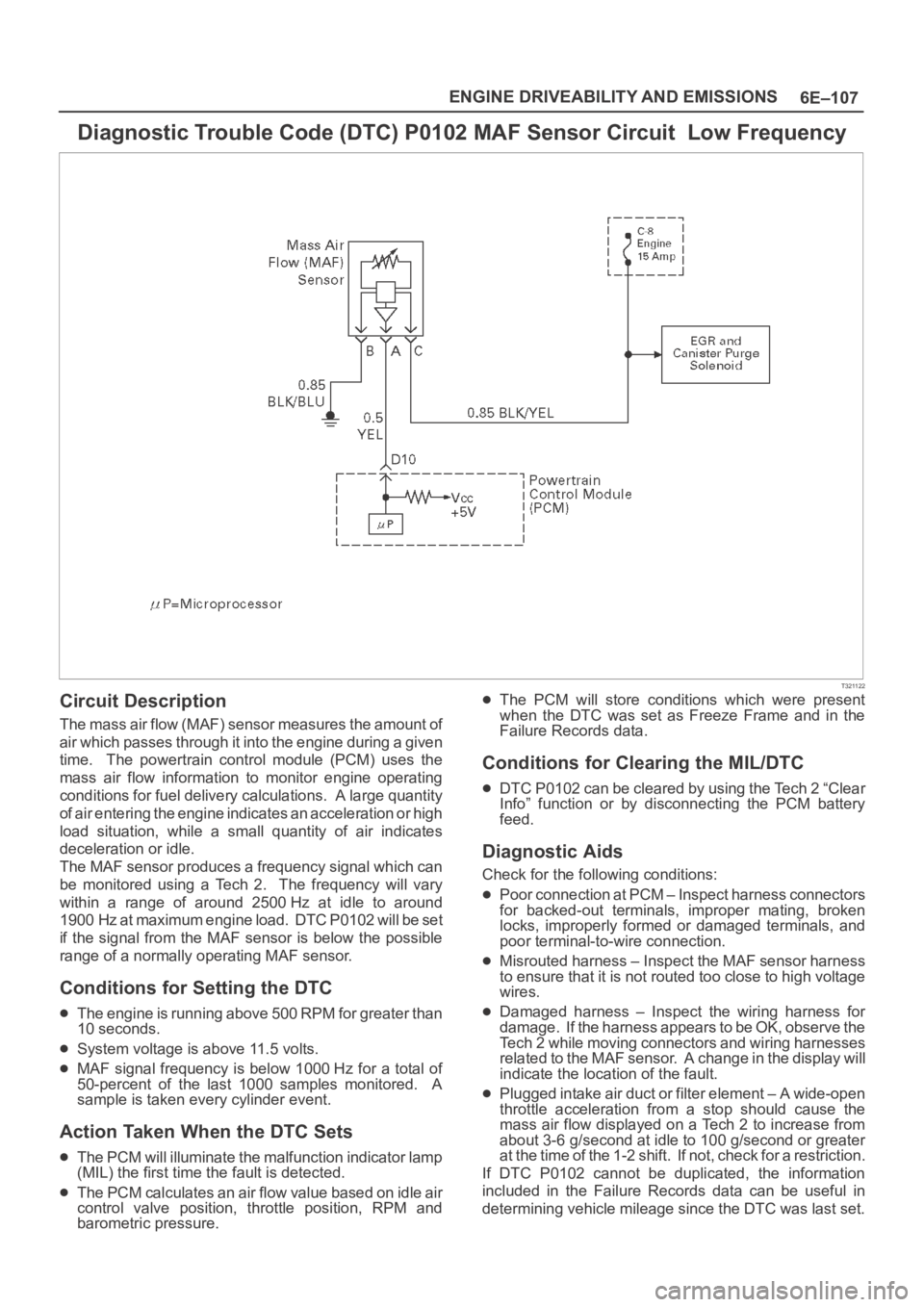
Diagnostic Trouble Code (DTC) P0102 MAF Sensor Circuit Low Frequency
T321122
Circuit Description
The mass air flow (MAF) sensor measures the amount of
air which passes through it into the engine during a given
time. The powertrain control module (PCM) uses the
mass air flow information to monitor engine operating
conditions for fuel delivery calculations. A large quantity
of air entering the engine indicates an acceleration or high
load situation, while a small quantity of air indicates
deceleration or idle.
The MAF sensor produces a frequency signal which can
be monitored using a Tech 2. The frequency will vary
within a range of around 2500 Hz at idle to around
1900 Hz at maximum engine load. DTC P0102 will be set
if the signal from the MAF sensor is below the possible
range of a normally operating MAF sensor.
Conditions for Setting the DTC
The engine is running above 500 RPM for greater than
10 seconds.
System voltage is above 11.5 volts.
MAF signal frequency is below 1000 Hz for a total of
50-percent of the last 1000 samples monitored. A
sample is taken every cylinder event.
Action Taken When the DTC Sets
The PCM will illuminate the malfunction indicator lamp
(MIL) the first time the fault is detected.
The PCM calculates an air flow value based on idle air
control valve position, throttle position, RPM and
barometric pressure.
The PCM will store conditions which were present
when the DTC was set as Freeze Frame and in the
Failure Records data.
Conditions for Clearing the MIL/DTC
DTC P0102 can be cleared by using the Tech 2 “Clear
Info” function or by disconnecting the PCM battery
feed.
Diagnostic Aids
Check for the following conditions:
Poor connection at PCM – Inspect harness connectors
for backed-out terminals, improper mating, broken
locks, improperly formed or damaged terminals, and
poor terminal-to-wire connection.
Misrouted harness – Inspect the MAF sensor harness
to ensure that it is not routed too close to high voltage
wires.
Damaged harness – Inspect the wiring harness for
damage. If the harness appears to be OK, observe the
Tech 2 while moving connectors and wiring harnesses
related to the MAF sensor. A change in the display will
indicate the location of the fault.
Plugged intake air duct or filter element – A wide-open
throttle acceleration from a stop should cause the
mass air flow displayed on a Tech 2 to increase from
about 3-6 g/second at idle to 100 g/second or greater
at the time of the 1-2 shift. If not, check for a restriction.
If DTC P0102 cannot be duplicated, the information
included in the Failure Records data can be useful in
determining vehicle mileage since the DTC was last set.
Page 1232 of 6000

6E–115 ENGINE DRIVEABILITY AND EMISSIONS
Diagnostic Trouble Code (DTC) P0108 MAP Sensor Circuit High Voltage
D06RW102
Circuit Description
The manifold absolute pressure (MAP) sensor responds
to changes in intake manifold pressure (vacuum). The
MAP sensor signal voltage to the powertrain control
module (PCM) varies from below 2 volts at idle (high
vacuum) to above 4 volts with the key “ON,” engine not
running or at wide-open throttle (low vacuum).
The MAP sensor is used to determine manifold pressure
changes while the linear EGR flow test diagnostic is being
run (refer to
DTC P0401), to determine engine vacuum
level for some other diagnostics and to determine
barometric pressure (BARO). The PCM monitors the
MAP signals for voltages outside the normal range of the
MAP sensor. If the PCM detects a MAP signal voltage
that is excessively high, DTC P0108 will be set.
Conditions for Setting the DTC
No TP sensor DTCs present.
Engine is running for more than 10 seconds.
Throttle position is below 3% if engine speed is below
1000 RPM.
Throttle position is below 10% if engine speed is above
1000 RPM.
The MAP sensor indicates an intermittent manifold
absolute pressure above 80kPa for a total of
approximately 10 seconds over a 16-second period.
Action Taken When the DTC Sets
The PCM will illuminate the malfunction indicator lamp
(MIL) the first time the fault is detected.
The PCM will default to a BARO value of 79.3 kPa.
The PCM will store conditions which were present
when the DTC was set as Freeze Frame and in the
Failure Records data.
Conditions for Clearing the MIL/DTC
DTC P0108 can be cleared by using the Tech 2 “Clear
Info” function or by disconnecting the PCM battery
feed.
Diagnostic Aids
Check for the following conditions:
Poor connection at PCM – Inspect harness connectors
for backed-out terminals, improper mating, broken
locks, improperly formed or damaged terminals, and
poor terminal-to-wire connection.
Damaged harness – Inspect the wiring harness for
damage. If the harness appears to be OK, observe the
MAP display on the Tech 2 while moving connectors
and wiring harnesses related to the sensor. A change
in the display will indicate the location of the fault.
If DTC P0108 cannot be duplicated, the information
included in the Failure Records data can be useful in
determining vehicle mileage since the DTC was last set. If
it is determined that the DTC occurs intermittently,
performing the DTC P1108 Diagnostic Chart may isolate
the cause of the fault.
Page 1235 of 6000

6E–118
ENGINE DRIVEABILITY AND EMISSIONS
Diagnostic Trouble Code (DTC) P0112 IAT Sensor Circuit Low Voltage
D06RW026
Circuit Description
The intake air temperature (IAT) sensor is a thermistor
which measures the temperature of the air entering the
engine. The powertrain control module (PCM) applies 5
volts through a pull-up resistor to the IAT sensor. When
the intake air is cold, the sensor resistance is high and the
PCM will monitor a high signal voltage on the IAT signal
circuit. If the intake air is warm, the sensor resistance is
lower, causing the PCM to monitor a lower voltage. DTC
P0112 will set when the PCM detects an excessively low
signal voltage on the intake air temperature sensor signal
circuit.
Conditions for Setting the DTC
The engine has been running for over 2 minutes.
Vehicle speed is greater than 30 mph (48 km/h) .
IAT signal voltage indicates and intake air temperature
greater than 148C (298F) (about 5 volts) for a total
of 12.5 seconds over a 25-second period of time.
Action Taken When the DTC Sets
The PCM will illuminate the malfunction indicator lamp
(MIL) the first time the fault is detected.
The PCM will store conditions which were present
when the DTC was set as Freeze Frame and in the
Failure Records data.
Conditions for Clearing the MIL/DTC
DTC P0112 can be cleared by using the Tech 2 “Clear
Info” function or by disconnecting the PCM battery
feed.
Diagnostic Aids
Check for the following conditions:
Poor connection at PCM – Inspect harness connectors
for backed-bout terminals, improper mating, broken
locks, improperly formed or damaged terminals, and
poor terminal-to-wire connection.
Damaged harness – Inspect the wiring harness for
damage. If the harness appears to be OK, observe the
IAT display on the Tech 2 while moving connectors and
wiring harnesses related to the IAT sensor. A change
in the IAT display will indicate the location of the fault.
If DTC P0112 cannot be duplicated, the information
included in the Failure Records data can be useful in
determining vehicle mileage since the DTC was last set.
Test Description
Number(s) below refer to the step number(s) on the
Diagnostic Chart:
2. Verifies that the fault is present.
Page 1238 of 6000

6E–121 ENGINE DRIVEABILITY AND EMISSIONS
Diagnostic Trouble Code (DTC) P0113 IAT Sensor Circuit High Voltage
D06RW026
Circuit Description
The intake air temperature (IAT) sensor is a thermistor
which measures the temperature of the air entering the
engine. The powertrain control module (PCM) applies 5
volts through a pull-up resistor to the IAT sensor. When
the intake air is cold, the sensor resistance is high and the
PCM will monitor a high signal voltage on the IAT signal
circuit. If the intake air is warm, the sensor resistance is
lower causing the PCM to monitor a lower voltage. DTC
P0113 will set when the PCM detects an excessively high
signal voltage on the intake air temperature sensor signal
circuit.
Conditions for Setting the DTC
The engine has been running for over 4 minutes.
Vehicle speed is less than 20 mph (32 km/h).
ECT signal temperature is above 60C (140F).
Mass air flow is less then 20 g/second.
IAT signal voltage indicates an intake air temperature
less than –39C (–38F) for total of 12.5 seconds over
a 25-second period.
Action Taken When the DTC Sets
The PCM will illuminate the malfunction indicator lamp
(MIL) the first time the fault is detected.
The PCM will store conditions which were present
when the DTC was set as Freeze Frame and in the
Failure Records data.
Conditions for Clearing the MIL/DTC
DTC P0113 can be cleared by using the Tech 2 “Clear
Info” function or by disconnecting the PCM battery
feed.
Diagnostic Aids
Check for the following conditions:
The IAT sensor shares a ground with the EGR position
sensor and the TP sensor. Check the ground if these
DTC’s are set.
Poor connection at PCM – Inspect harness connectors
for backed-out terminals, improper mating, broken
locks, improperly formed or damaged terminals, and
poor terminal-to-wire connection.
Damaged harness – Inspect the wiring harness for
damage. If the harness appears to be OK, observe the
IAT display on the Tech 2 while moving connectors and
wiring harnesses related to the IAT sensor. A change
in the IAT display will indicate the location of the fault.
If DTC P0113 cannot be duplicated, the information
included in the Failure Records data can be useful in
determining vehicle mileage since the DTC was last set.
Test Description
Number(s) below refer to the step number(s) on the
Diagnostic Chart:
2. Verifies that the fault is present.
Page 1241 of 6000

6E–124
ENGINE DRIVEABILITY AND EMISSIONS
Diagnostic Trouble Code (DTC) P0117 ECT Sensor Circuit Low Voltage
060RY00304
Circuit Description
The engine coolant temperature (ETC) sensor is a
thermistor mounted on a coolant crossover pipe at the
rear of the engine. The powertrain control module (PCM)
applies a voltage (about 5 volts) through a pull-up resistor
to the ECT signal circuit. When the engine coolant is cold,
the sensor (thermistor) resistance is high, therefore the
PCM will measure a high signal voltage. As the engine
coolant warms, the sensor resistance becomes lower,
and the ECT signal voltage measured at the PCM drops.
With a fully warmed-up engine, the ECT signal voltage
should measure about 1.5 to 2.0 volts.
Conditions for Setting the DTC
Engine running time is longer than one minute.
The ECT sensor signal indicates an engine coolant
temperature greater than 150C (302F) (about 0.10
V) for a total of 50 seconds over a 100–second period.
Action Taken When the DTC Sets
The PCM will illuminate the malfunction indicator lamp
(MIL) the first time the fault is detected.
The PCM will substitute the ECT reading with a default
engine coolant temperature value. The default value
is based on start-up intake air temperature and running
time.
The PCM will store conditions which were present
when the DTC was set as Freeze Frame and in the
Failure Records data.
Conditions for Clearing the MIL/DTC
DTC P0117 can be cleared by using the Tech 2 “Clear
Info” function or by disconnecting the PCM battery
feed.
Diagnostic Aids
Check for the following conditions:
Poor connection at PCM – Inspect harness connectors
for backed-out terminals, improper mating, broken
locks, improperly formed or damaged terminals, and
poor terminal-to-wire connection.
Damaged harness – Inspect the wiring harness for
damage. If the harness appears to be OK, observe the
ECT display on the Tech 2 while moving connectors
and wiring harnesses related to the ECT sensor. A
change in the ECT display will indicate the location of
the fault.
If DTC P0117 cannot be duplicated, the information
included in the Failure Records data can be useful in
determining vehicle mileage since the DTC was last set.
Test Description
Number(s) below refer to the step number(s) on the
Diagnostic Chart.
Page 1244 of 6000
6E–127 ENGINE DRIVEABILITY AND EMISSIONS
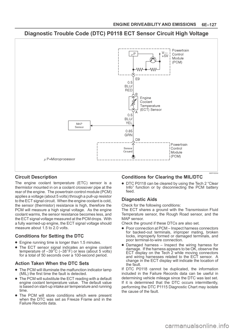
Diagnostic Trouble Code (DTC) P0118 ECT Sensor Circuit High Voltage
060RY00304
Circuit Description
The engine coolant temperature (ETC) sensor is a
thermistor mounted in on a coolant crossover pipe at the
rear of the engine. The powertrain control module (PCM)
applies a voltage (about 5 volts) through a pull-up resistor
to the ECT signal circuit. When the engine coolant is cold,
the sensor (thermistor) resistance is high, therefore the
PCM will measure a high signal voltage. As the engine
coolant warms, the sensor resistance becomes less, and
the ECT signal voltage measured at the PCM drops. With
a fully warmed-up engine, the ECT signal voltage should
measure about 1.5 to 2.0 volts.
Conditions for Setting the DTC
Engine running time is longer than 1.5 minutes.
The ECT sensor signal indicates an engine coolant
temperature of –39C (–38F) or less (about 5 volts)
for a total of 50 seconds over a 100-second period.
Action Taken When the DTC Sets
The PCM will illuminate the malfunction indicator lamp
(MIL) the first time the fault is detected.
The PCM will substitute the ECT reading with a default
engine coolant temperature value. The default value
is based on start-up intake air temperature and running
time.
The PCM will store conditions which were present
when the DTC was set as Freeze Frame and in the
Failure Records data.
Conditions for Clearing the MIL/DTC
DTC P0118 can be cleared by using the Tech 2 “Clear
Info” function or by disconnecting the PCM battery
feed.
Diagnostic Aids
Check for the following conditions:
The ECT shares a ground with the Transmission Fluid
Temperature sensor, the Rough Road sensor, and the
MAP sensor.
Check the ground if these DTCs are also set.
Poor connection at PCM – Inspect harness connectors
for backed-out terminals, improper mating, broken
locks, improperly formed or damaged terminals, and
poor terminal-to-wire connection.
Damaged harness – Inspect the wiring harness for
damage. If the harness appears to be OK, observe the
ECT display on the Tech 2 while moving connectors
and wiring harnesses related to the ECT sensor. A
change in the ECT display will indicate the location of
the fault.
If DTC P0118 cannot be duplicated, the information
included in the Failure Records data can be useful in
determining vehicle mileage since the DTC was last set.
If it is determined that the DTC occurs intermittently,
performing the DTC P1115 Diagnostic Chart may isolate
the cause of the fault.