ESP OPEL FRONTERA 1998 Workshop Manual
[x] Cancel search | Manufacturer: OPEL, Model Year: 1998, Model line: FRONTERA, Model: OPEL FRONTERA 1998Pages: 6000, PDF Size: 97 MB
Page 4094 of 6000

4B2–11 DRIVE LINE CONTROL SYSTEM (TOD)
The CHECK lamp also has the following functions.
D-G MAP recognition and display (The control unit
displays what type of vehicle, diesel or gasoline
vehicle, it recognizes.)
1. Short-circuit the self-diagnostic connector.
2. Turn on the starter switch. (Displays with respect to
the self-diagnosis begin to appear.)
NOTE: Do not start the engine.
3. Shift the transfer lever to the neutral position between
HIGH and 4L.
4. After all the conditions in 1 through 3 above are met,
set the throttle to the WOT (wide open throttle)
position (i.e., full open position). The display of the
self-diagnosis is temporarily suspended, and the
CHECK lamp begins to display that MAP is
recognized by the TPS (throttle position sensor)
according to the current conditions.NOTE: If the TPS has failed, this function might not work.
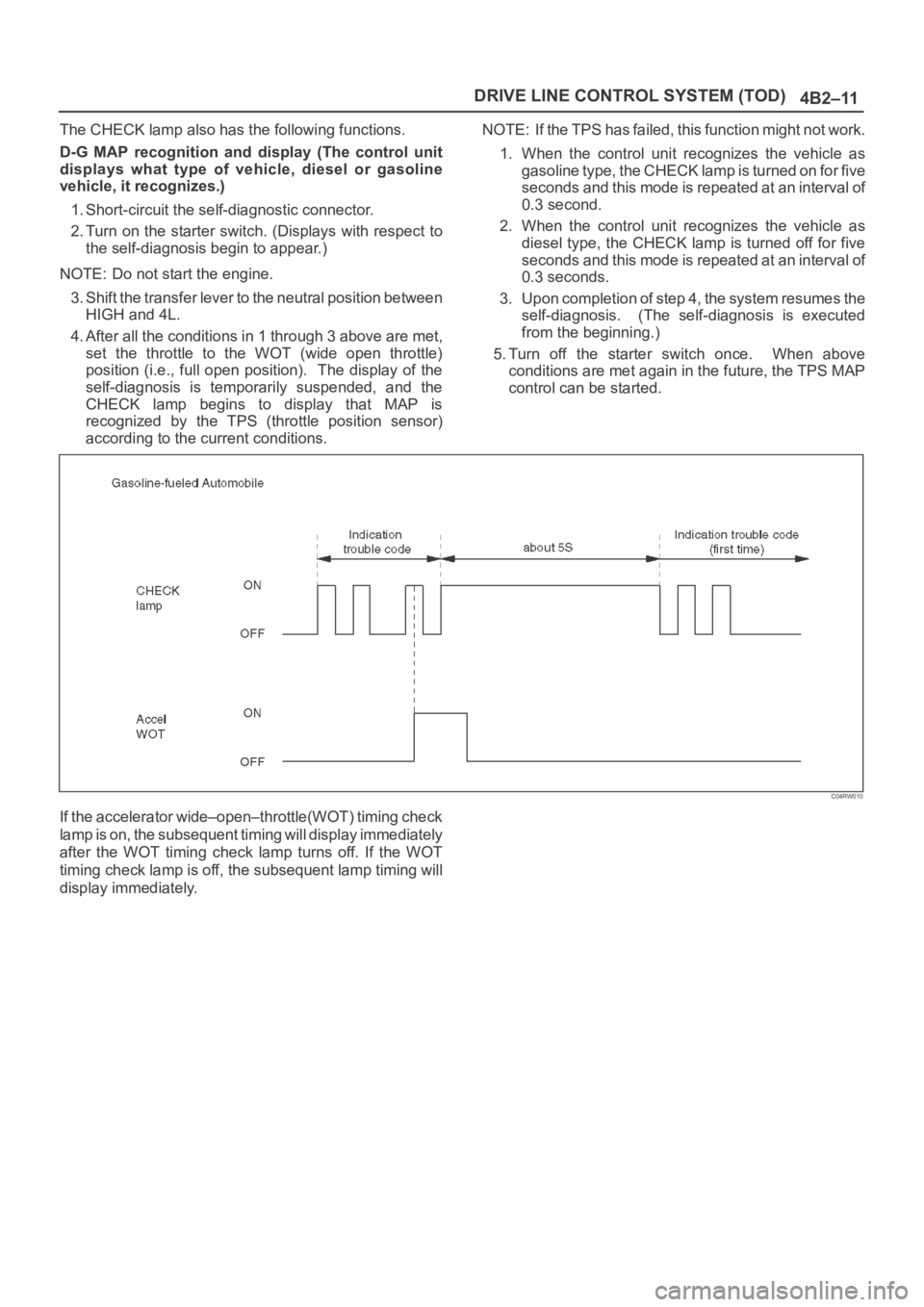
1. When the control unit recognizes the vehicle as
gasoline type, the CHECK lamp is turned on for five
seconds and this mode is repeated at an interval of
0.3 second.
2. When the control unit recognizes the vehicle as
diesel type, the CHECK lamp is turned off for five
seconds and this mode is repeated at an interval of
0.3 seconds.
3. Upon completion of step 4, the system resumes the
self-diagnosis. (The self-diagnosis is executed
from the beginning.)
5. Turn off the starter switch once. When above
conditions are met again in the future, the TPS MAP
control can be started.
C04RW010
If the accelerator wide–open–throttle(WOT) timing check
lamp is on, the subsequent timing will display immediately
after the WOT timing check lamp turns off. If the WOT
timing check lamp is off, the subsequent lamp timing will
display immediately.
Page 4097 of 6000

DRIVE LINE CONTROL SYSTEM (TOD) 4B2–14
Indication Method of Trouble Code
Short-circuit terminal 8 of the self-diagnostic
connector to GND to display the trouble code on the
CHECK lamp.
810RW308
If no trouble codes exist, code “12” is displayed
continuously.
If trouble codes exist, code “12” is displayed three
times, and the trouble codes, starting from the smaller
code number, are displayed three times respectively.
C07RW013
Page 4130 of 6000

4B2–47 DRIVE LINE CONTROL SYSTEM (TOD)
Check flowTrouble codePhenomenonStandard
316
(P1737)The front speed sensor no pulse.Hi level : 4.5 6.0 V
Lo level : 0.7
2.0 V
Frequency (F) =
700–850 Hz (at 50 km/h)
NOTE: Find the trouble in which the pulse corresponding
to the running speed is not input.
D04RY00059
Page 4132 of 6000

4B2–49 DRIVE LINE CONTROL SYSTEM (TOD)
Check flowTrouble codePhenomenonStandard
427
(P1738)The rear speed sensor no pulse.Hi level : 4.5 6.0 V
Lo level : 0.7
2.0 V
Frequency (F) =
700–850 Hz (at 50 km/h)
NOTE: Find the trouble in which the pulse corresponding
to the running speed is not input.
D04RY00059
Page 4219 of 6000

4C–13 DRIVE SHAFT SYSTEM
9. Install lock washer and lock screw in the following
manner.
Turn the side with larger diameter of the tapered
bore to the vehicle outer side, then attach the
washer.
If the bolt holes in the lock plate are not aligned with
the corresponding holes in the nut, reverse the lock
plate.
If the bolt holes are still out of alignment, turn in the
nut just enough to obtain alignment.
Screw is to be fastened tightly so its head may
come lower than the surface of the washer.
411RS012
10. Apply adhesive (LOCTITE 515 or equivalent) to both
joining flange faces then install hub flange.
11. Install snap ring and shim.
Adjust the clearance between the free wheeling hub
body and the snap ring.
Clearance: 0 mm–0.3 mm (0 in–0.012 in)
Shims Available: 0.2 mm, 0.3 mm, 0.5 mm,
1.0 mm (0.008 in, 0.012 in, 0.020 in, 0.039 in)
411RW002
12. Install hub cap.
13. Tighten the bolts to the specified torque.
Torque: 59 Nꞏm (6.0 kgꞏm/43 lb ft)
Page 4225 of 6000

4C–19 DRIVE SHAFT SYSTEM
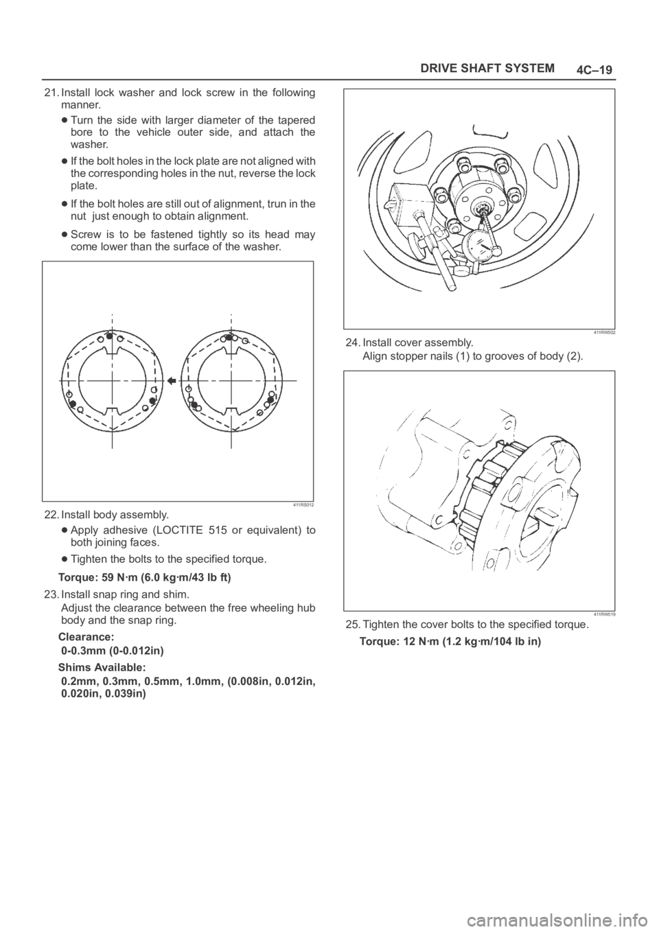
21. Install lock washer and lock screw in the following
manner.
Turn the side with larger diameter of the tapered
bore to the vehicle outer side, and attach the
washer.
If the bolt holes in the lock plate are not aligned with
the corresponding holes in the nut, reverse the lock
plate.
If the bolt holes are still out of alignment, trun in the
nut just enough to obtain alignment.
Screw is to be fastened tightly so its head may
come lower than the surface of the washer.
411RS012
22. Install body assembly.
Apply adhesive (LOCTITE 515 or equivalent) to
both joining faces.
Tighten the bolts to the specified torque.
Torque:59Nꞏm (6.0kgꞏm/43lbft)
23. Install snap ring and shim.
Adjust the clearance between the free wheeling hub
body and the snap ring.
Clearance:
0-0.3mm (0-0.012in)
Shims Available:
0.2mm, 0.3mm, 0.5mm, 1.0mm, (0.008in, 0.012in,
0.020in, 0.039in)
411RW002
24. Install cover assembly.
Align stopper nails (1) to grooves of body (2).
411RW019
25. Tighten the cover bolts to the specified torque.
Torque:12Nꞏm (1.2kgꞏm/104lbin)
Page 4336 of 6000

4D2–29 TRANSFER CASE (TOD)
Cam Pulley, Cam Ball, and Cam&Coil
Housing
Check the cam balls and cam for excessive wear or
damage. If defective, replace the parts.
266RW016
The Parts 4H and 4L Switch
Check the continuity of 4H and 4L switch.
261RW003
261RW049
Switch
Stroke4H Switch
Signal4L Switch
SignalThe
correspo
nding
p
ositionB to Switch
BodyA to Cosition
of
transfer
lever
1OpenOpenHigh
2OpenClose4L
3CloseCloseNeutral
Page 4356 of 6000

5A–6
BRAKE CONTROL SYSTEM
Test Driving ABS Complaint Vehicles
In case that there has been an malfunction in the lighting
pattern of “ABS” warning light, the fault can be located in
accordance with the “DIAGNOSIS BY “ABS” WARNING
LIGHT ILLUMINATION PATTERN” . In case of such
trouble as can be detected by the driver as a vehicle
symptom, however, it is necessary to give a test drive
following the test procedure mentioned below, thereby
reproducing the symptom for trouble diagnosis on a
symptom basis:
1. Start the engine and make sure that the “ABS” W/L
goes OFF. If the W/L remains ON, it means that the
Diagnostic Trouble Code (DTC) is stored. Therefore,
read the code and locate the fault.
2. Start the vehicle and accelerate to about 30 km/h (19
mph) or more.
3. Slowly brake and stop the vehicle completely.
4. Then restart the vehicle and accelerate to about 40
km/h (25 mph) or more.
5. Brake at a time so as to actuate the ABS and stop the
vehicle.
6. Be cautious of abnormality during the test. If the W/L
is actuated while driving, read the DTC and locate the
fault.
7. If the abnormality is not reproduced by the test, make
best efforts to reproduce the situation reported by the
customer.
8. If the abnormality has been detected, repair in
accordance with the “SYMPTOM DIAGNOSIS” .NOTE:Be sure to give a test drive on a wide, even road with
little traffic.
If an abnormality is detected, be sure to suspend the
test and start trouble diagnosis at once.
“ABS” Warning Light
When ABS trouble occurs and actuates when possible
the “ABS” warning light, the trouble code corresponding
to the trouble is stored in the EHCU. Only the ordinary
brake system is available when the ABS is turned off.
When the “ABS” warning light is actuated, if the starter
switch is set ON after setting it OFF once, the EHCU
checks up on the entire system and, if there is no
abnormality, judges ABS to work currently and the
warning light works normally even though the trouble
code is stored.
NOTE: Illumination of the “ABS” warning light indicates
that anti-lock braking is no longer available. Power
assisted braking without anti-lock control is still available.
Normal Operation
“ABS” Warning Light
W h e n t h e i g n i t i o n i s f i r s t m o v e d f r o m “ O F F ” t o “ R U N ” , t h e
amber “ABS” warning light will turn “ON” . The “ABS”
warning light will turn “ON” during engine starting and will
usually stay “ON” for approximately three seconds after
the ignition switch is returned to the “ON” position. The
warning light should remain “OFF” at all other times.
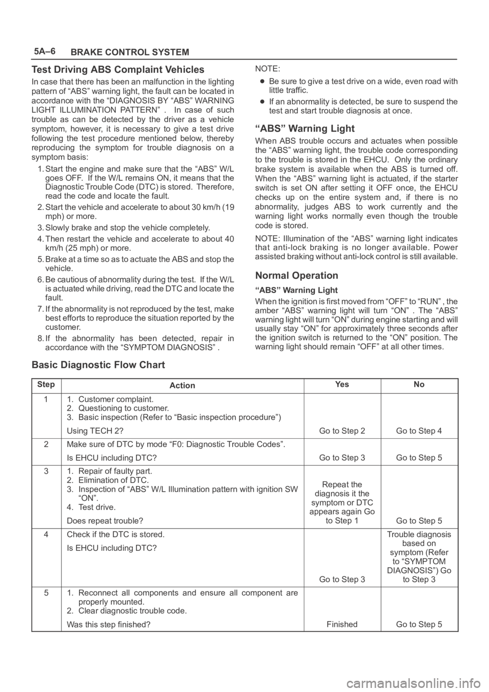
Basic Diagnostic Flow Chart
StepActionYe sNo
11. Customer complaint.
2. Questioning to customer.
3. Basic inspection (Refer to “Basic inspection procedure”)
Using TECH 2?
Go to Step 2Go to Step 4
2Make sure of DTC by mode “F0: Diagnostic Trouble Codes”.
Is EHCU including DTC?
Go to Step 3Go to Step 5
31. Repair of faulty part.
2. Elimination of DTC.
3. Inspection of “ABS” W/L Illumination pattern with ignition SW
“ON”.
4. Test drive.
Does repeat trouble?
Repeat the
diagnosis it the
symptom or DTC
appears again Go
to Step 1
Go to Step 5
4Check if the DTC is stored.
Is EHCU including DTC?
Go to Step 3
Trouble diagnosis
based on
symptom (Refer
to “SYMPTOM
DIAGNOSIS”) Go
to Step 3
51. Reconnect all components and ensure all component are
properly mounted.
2. Clear diagnostic trouble code.
Was this step finished?
FinishedGo to Step 5
Page 4508 of 6000

6A–12
ENGINE MECHANICAL
ConditionPossible causeCorrection
Noise from connecting rods or from
connecting rod bearings
(Faulty connecting rods orBearing or crankshaft pin wornReplace connecting rod bearings
and crankshaft or regrind crankshaft
pin and install the undersize bearing
yg
connecting rod bearings usually
make an abnormal noise slightly
higher than the crank bearing noise,
which becomes more evident when
Crankpin out of roundReplace connecting rod bearings
and crankshaft or regrind crankshaft
pin and install the undersize bearing
which becomes more evident when
engine is accelerated)Connecting rod bentCorrect or replaceg)
Connecting rod bearing seizedReplace connecting rod bearings
and crankshaft or regrind crankshaft
pin and install the undersize bearing
Troubleshooting Procedure
Abnormal noise stops when the spark plug on the cylinder
with defective part is shorted out.
Condition
Possible causeCorrection
Piston and cylinder noise
(Faulty piston or cylinder usually
kbidhil
Piston clearance increased due to
cylinder wearReplace piston and cylinder body
makes a combined mechanical
thumping noise which increasesPiston seizedReplace piston and cylinder bodyg
when engine is suddenly accelerated
but diminishes
gradually as thePiston ring brokenReplace piston and cylinder bodybut diminishes gradually as the
engine warms up)Piston defectiveReplace pistons and others
Troubleshooting Procedure
Short out each spark plug and listen for change in engine
noise.
Condition
Possible causeCorrection
Piston pin noise
(Piston makes noise each time it
goes up and down)Piston pin or piston pin hole wornReplace piston, piston pin and
connecting rod assy
Troubleshooting Procedure
The slapping sound stops when spark plug on bad
cylinder is shorted out.
Condition
Possible causeCorrection
Timing belt noiseTiming belt tension is incorrectReplace pusher or adjust the tension
pulley or replace timing belt
Tensioner bearing defectiveReplace
Timing belt defectiveReplace
Timing pulley defectiveReplace
Timing belt comes in contact with
timing coverReplace timing belt and timing cover
Valve noiseValve clearance incorrectReplace adjusting shim
Valve and valve guide seizedReplace valve and valve guide
Valve spring broken or weakenedReplace
Valve seat off–positionedCorrect
Camshaft worn outReplace
Crankshaft noiseCrankshaft end play excessive
(noise occurs when clutch is
engaged)Replace thrust bearing
Page 4539 of 6000

6A–43
ENGINE MECHANICAL
6. Remove oil pump assembly.
Refer to removal procedure for Oil Pump in this
manual.
7. Remove cylinder body side bolts.
8. Remove oil gallery.
9. Remove flywheel.
10. Remove rear oil seal retainer.
Refer to removal procedure for Rear Oil Seal in this
manual.
11. Remove connecting rod caps.
12. Remove crankshaft main bearing caps.
13. Remove crankshaft and main bearings.
Installation
1. Install crankshaft and main bearings.
Install main bearing in the cylinder block and main
bearing cap respectively.
Apply new engine oil to upper and lower main
bearings.
NOTE:
Do not apply engine oil to the bearing back faces.
Make sure that main bearings are in correct position.
Install crankshaft with care.
Apply engine oil to the thrust washer.
Install thrust washer on No.3 journal.
Oil grooves in thrust washer must face the
crankshaft.
015RS012
015RS013
2. Install crankshaft main bearing caps.
Apply engine oil to the thread and seating surface of
each bearing cap fixing bolt.
NOTE:
Do not apply engine oil to the bearing back faces.
Install bearing caps in the order of numbers, starting
with cylinder block front side.
Tighten main bearing fixing bolts to the specified
torque.
Torque : 39 Nꞏm (4.0 Kgꞏm/29 lb ft)
After tightening the bolts, make sure that the
crankshaft rotates smoothly.
3. Install connecting rod caps.
The cap number must be same as connecting rod
number.
Apply engine oil to the thread and seating surface of
each nut.
Tighten nuts to the specified torque.
Torque : 54 Nꞏm (5.5 Kgꞏm/40 lb ft)
After tightening the nuts, make sure that the
crankshaft rotates smoothly.
4. Install rear oil seal retainer.
Remove oil on cylinder block and retainer fitting
surface.
Apply sealant (TB1207B or equivalent) to retainer
fitting surface as shown in illustration.