torque OPEL FRONTERA 1998 User Guide
[x] Cancel search | Manufacturer: OPEL, Model Year: 1998, Model line: FRONTERA, Model: OPEL FRONTERA 1998Pages: 6000, PDF Size: 97 MB
Page 445 of 6000
DIFFERENTIAL (FRONT) 4A1–8
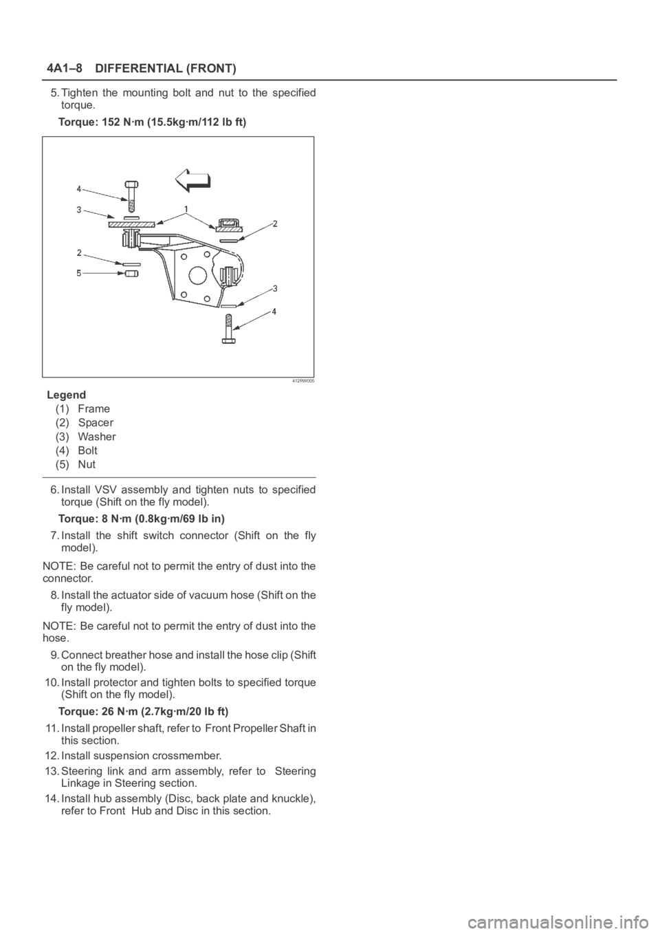
5. Tighten the mounting bolt and nut to the specified
torque.
Torque: 152 Nꞏm (15.5kgꞏm/112 lb ft)
412RW005
Legend
(1) Frame
(2) Spacer
(3) Washer
(4) Bolt
(5) Nut
6. Install VSV assembly and tighten nuts to specified
torque (Shift on the fly model).
Torque: 8 Nꞏm (0.8kgꞏm/69 lb in)
7. Install the shift switch connector (Shift on the fly
model).
NOTE: Be careful not to permit the entry of dust into the
connector.
8. Install the actuator side of vacuum hose (Shift on the
fly model).
NOTE: Be careful not to permit the entry of dust into the
hose.
9. Connect breather hose and install the hose clip (Shift
on the fly model).
10. Install protector and tighten bolts to specified torque
(Shift on the fly model).
Torque: 26 Nꞏm (2.7kgꞏm/20 lb ft)
11. Install propeller shaft, refer to Front Propeller Shaft in
this section.
12. Install suspension crossmember.
13. Steering link and arm assembly, refer to Steering
Linkage in Steering section.
14. Install hub assembly (Disc, back plate and knuckle),
refer to Front Hub and Disc in this section.
Page 449 of 6000
DIFFERENTIAL (FRONT) 4A1–12
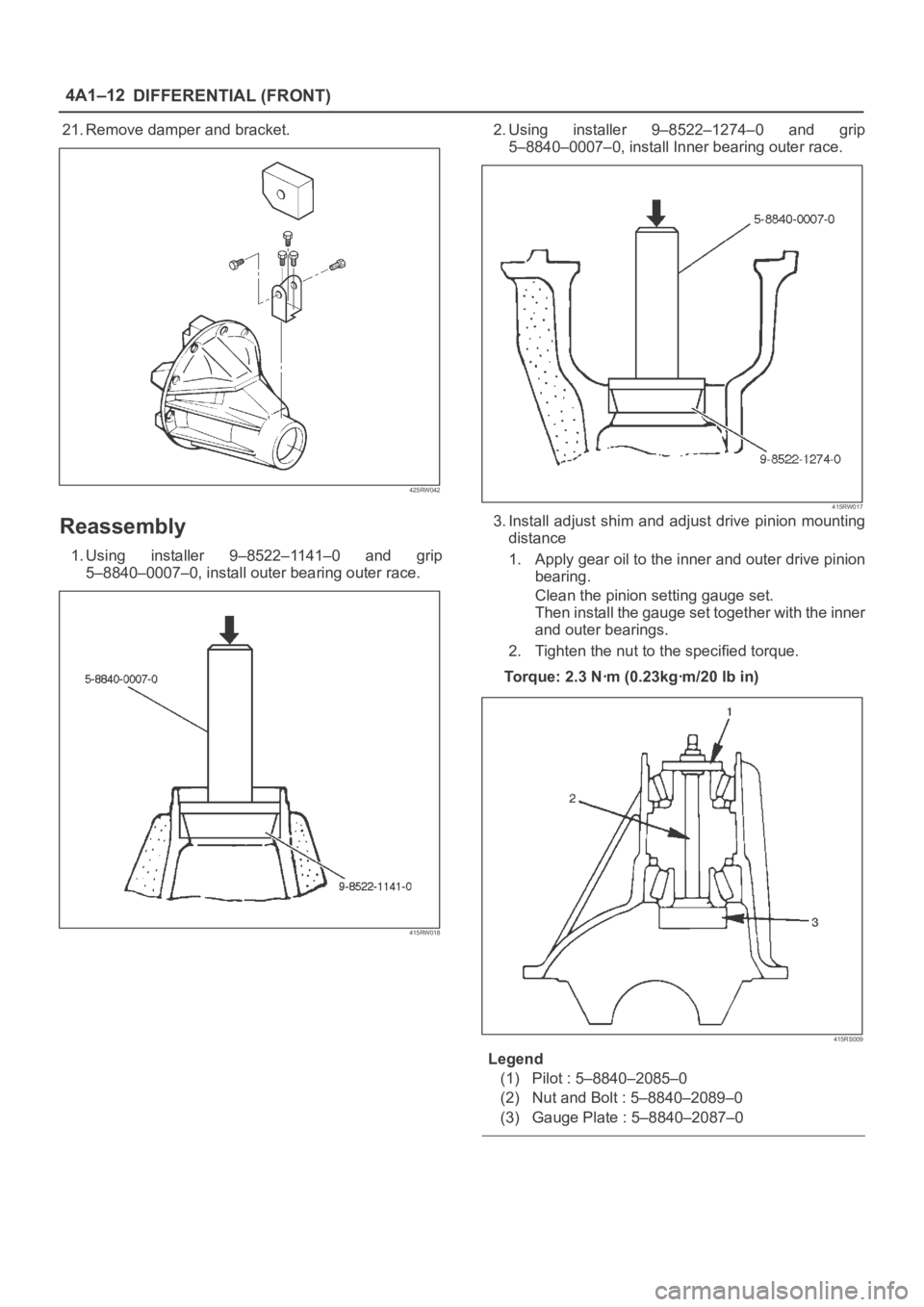
21. Remove damper and bracket.
425RW042
Reassembly
1. Using installer 9–8522–1141–0 and grip
5–8840–0007–0, install outer bearing outer race.
415RW018
2. Using installer 9–8522–1274–0 and grip
5–8840–0007–0, install Inner bearing outer race.
415RW017
3. Install adjust shim and adjust drive pinion mounting
distance
1. Apply gear oil to the inner and outer drive pinion
bearing.
Clean the pinion setting gauge set.
Then install the gauge set together with the inner
and outer bearings.
2. Tighten the nut to the specified torque.
Torque: 2.3 Nꞏm (0.23kgꞏm/20 lb in)
415RS009
Legend
(1) Pilot : 5–8840–2085–0
(2) Nut and Bolt : 5–8840–2089–0
(3) Gauge Plate : 5–8840–2087–0
Page 450 of 6000
4A1–13 DIFFERENTIAL (FRONT)
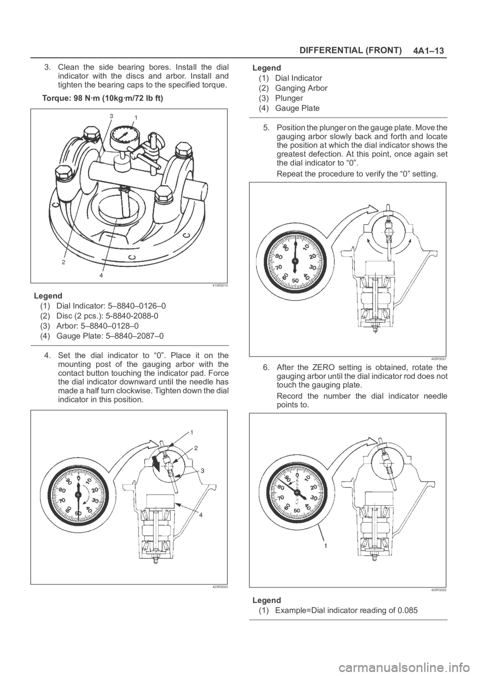
3. Clean the side bearing bores. Install the dial
indicator with the discs and arbor. Install and
tighten the bearing caps to the specified torque.
To r q u e : 9 8 N ꞏm ( 1 0 k g ꞏm / 7 2 l b f t )
415RS010
Legend
(1) Dial Indicator: 5–8840–0126–0
(2) Disc (2 pcs.): 5-8840-2088-0
(3) Arbor: 5–8840–0128–0
(4) Gauge Plate: 5–8840–2087–0
4. Set the dial indicator to “0”. Place it on the
mounting post of the gauging arbor with the
contact button touching the indicator pad. Force
the dial indicator downward until the needle has
made a half turn clockwise. Tighten down the dial
indicator in this position.
425RS020
Legend
(1) Dial Indicator
(2) Ganging Arbor
(3) Plunger
(4) Gauge Plate
5. Position the plunger on the gauge plate. Move the
gauging arbor slowly back and forth and locate
the position at which the dial indicator shows the
greatest defection. At this point, once again set
the dial indicator to “0”.
Repeat the procedure to verify the “0” setting.
425RS021
6. After the ZERO setting is obtained, rotate the
gauging arbor until the dial indicator rod does not
touch the gauging plate.
Record the number the dial indicator needle
points to.
425RS022
Legend
(1) Example=Dial indicator reading of 0.085
Page 453 of 6000
DIFFERENTIAL (FRONT) 4A1–16
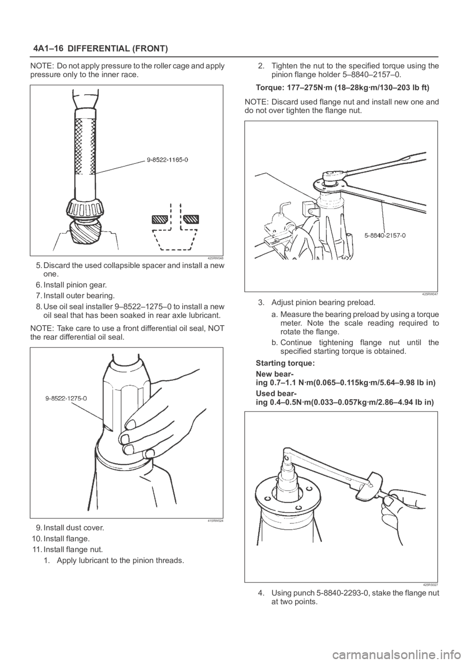
NOTE: Do not apply pressure to the roller cage and apply
pressure only to the inner race.
425RW048
5. Discard the used collapsible spacer and install a new
one.
6. Install pinion gear.
7. Install outer bearing.
8. Use oil seal installer 9–8522–1275–0 to install a new
oil seal that has been soaked in rear axle lubricant.
NOTE: Take care to use a front differential oil seal, NOT
the rear differential oil seal.
415RW024
9. Install dust cover.
10. Install flange.
11. Install flange nut.
1. Apply lubricant to the pinion threads.2. Tighten the nut to the specified torque using the
pinion flange holder 5–8840–2157–0.
Torque: 177–275Nꞏm (18–28kgꞏm/130–203 lb ft)
NOTE: Discard used flange nut and install new one and
do not over tighten the flange nut.
425RW047
3. Adjust pinion bearing preload.
a. Measure the bearing preload by using a torque
meter. Note the scale reading required to
rotate the flange.
b. Continue tightening flange nut until the
specified starting torque is obtained.
Starting torque:
New bear-
ing 0.7–1.1 Nꞏm(0.065–0.115kgꞏm/5.64–9.98 lb in)
Used bear-
ing 0.4–0.5Nꞏm(0.033–0.057kgꞏm/2.86–4.94 Ib in)
425RS027
4. Using punch 5-8840-2293-0, stake the flange nut
at two points.
Page 456 of 6000
4A1–19 DIFFERENTIAL (FRONT)
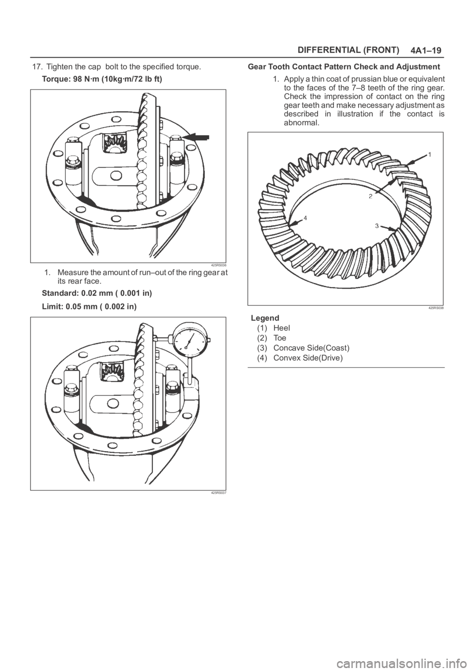
17. Tighten the cap bolt to the specified torque.
To r q u e : 9 8 N ꞏm ( 1 0 k g ꞏm / 7 2 l b f t )
425RS036
1. Measure the amount of run–out of the ring gear at
its rear face.
Standard: 0.02 mm ( 0.001 in)
Limit: 0.05 mm ( 0.002 in)
425RS037
Gear Tooth Contact Pattern Check and Adjustment
1. Apply a thin coat of prussian blue or equivalent
to the faces of the 7–8 teeth of the ring gear.
Check the impression of contact on the ring
gear teeth and make necessary adjustment as
described in illustration if the contact is
abnormal.
425RS038
Legend
(1) Heel
(2) Toe
(3) Concave Side(Coast)
(4) Convex Side(Drive)
Page 457 of 6000
DIFFERENTIAL (FRONT) 4A1–20
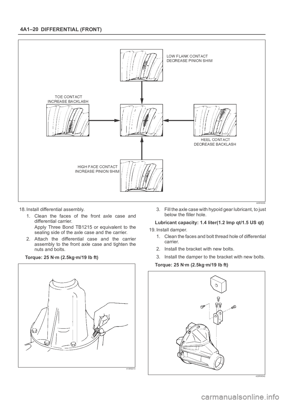
425RS039
18. Install differential assembly.
1. Clean the faces of the front axle case and
differential carrier.
Apply Three Bond TB1215 or equivalent to the
sealing side of the axle case and the carrier.
2. Attach the differential case and the carrier
assembly to the front axle case and tighten the
nuts and bolts.
To r q u e : 2 5 N ꞏm ( 2 . 5 k g ꞏm / 1 9 l b f t )
415RS014
3. Fill the axle case with hypoid gear lubricant, to just
below the filler hole.
Lubricant capacity: 1.4 liter(1.2 Imp qt/1.5 US qt)
19. Install damper.
1. Clean the faces and bolt thread hole of differential
carrier.
2. Install the bracket with new bolts.
3. Install the damper to the bracket with new bolts.
Torque: 25 Nꞏm (2.5kgꞏm/19 lb ft)
425RW042
Page 459 of 6000
DIFFERENTIAL (FRONT) 4A1–22
4. Remove the cross pin, using a soft metal rod and a
hammer.
425RS043
5. Remove pinion gear.
6. Remove side gear.
7. Remove thrust washer.
Inspection and Repair
Make necessary correction or parts replacement if wear,
damage, corrosion or any other abnormal conditions are
found through inspection.
Check the following parts:
1. Ring gear, pinion gear
2. Bearing
3. Side gear, pinion gear, cross pin
4. Differential cage, carrier
5. Thrust washer
6. Oil seal
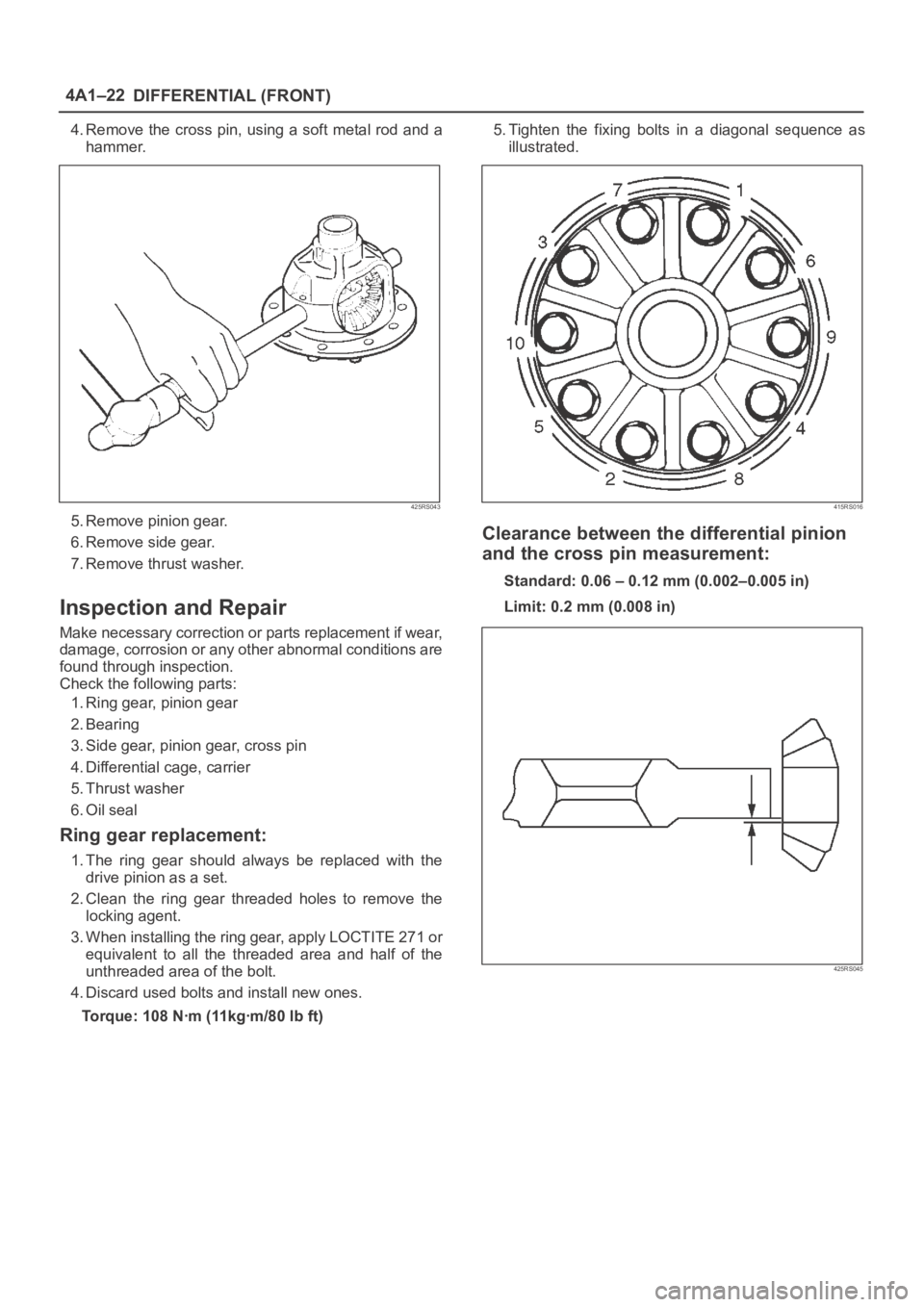
Ring gear replacement:
1. The ring gear should always be replaced with the
drive pinion as a set.
2. Clean the ring gear threaded holes to remove the
locking agent.
3. When installing the ring gear, apply LOCTITE 271 or
equivalent to all the threaded area and half of the
unthreaded area of the bolt.
4. Discard used bolts and install new ones.
Torque: 108 Nꞏm (11kgꞏm/80 lb ft)5. Tighten the fixing bolts in a diagonal sequence as
illustrated.
415RS016
Clearance between the differential pinion
and the cross pin measurement:
Standard: 0.06 – 0.12 mm (0.002–0.005 in)
Limit: 0.2 mm (0.008 in)
425RS045
Page 461 of 6000
DIFFERENTIAL (FRONT) 4A1–24
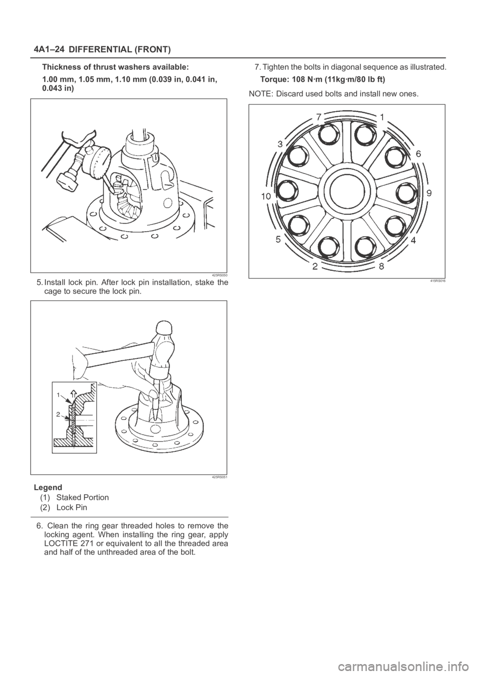
Thickness of thrust washers available:
1.00 mm, 1.05 mm, 1.10 mm (0.039 in, 0.041 in,
0.043 in)
425RS050
5. Install lock pin. After lock pin installation, stake the
cage to secure the lock pin.
425RS051
Legend
(1) Staked Portion
(2) Lock Pin
6. Clean the ring gear threaded holes to remove the
locking agent. When installing the ring gear, apply
LOCTITE 271 or equivalent to all the threaded area
and half of the unthreaded area of the bolt.7. Tighten the bolts in diagonal sequence as illustrated.
Torque: 108 Nꞏm (11kgꞏm/80 lb ft)
NOTE: Discard used bolts and install new ones.
415RS016
Page 463 of 6000
DIFFERENTIAL (FRONT) 4A1–26
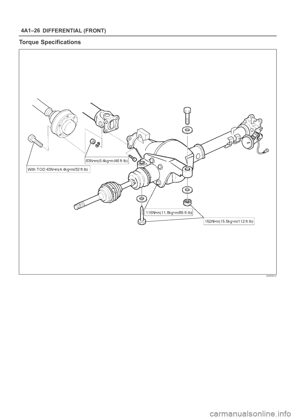
Torque Specifications
E04RW014
Page 468 of 6000
DIFFERENTIAL (REAR 220mm)
4A2A–1
DRIVELINE/AXLE
DIFFERENTIAL (Rear 220mm)
CONTENTS
Service Precaution 4A2A–1. . . . . . . . . . . . . . . . . . . . . .
General Description 4A2A–2. . . . . . . . . . . . . . . . . . . . .
Diagnosis 4A2A–3. . . . . . . . . . . . . . . . . . . . . . . . . . . . . .
Axle Housing 4A2A–4. . . . . . . . . . . . . . . . . . . . . . . . . . .
Axle Housing and Associated Parts 4A2A–4. . . . . .
Removal 4A2A–4. . . . . . . . . . . . . . . . . . . . . . . . . . . . .
Oil Seal Replacement 4A2A–5. . . . . . . . . . . . . . . . . .
Installation 4A2A–5. . . . . . . . . . . . . . . . . . . . . . . . . . . .
Pinion Oil Seal 4A2A–6. . . . . . . . . . . . . . . . . . . . . . . . . .
Pinion Oil Seal and Associated Parts 4A2A–6. . . . .
Removal 4A2A–6. . . . . . . . . . . . . . . . . . . . . . . . . . . . .
Inspection and Repair 4A2A–7. . . . . . . . . . . . . . . . . .
Installation 4A2A–7. . . . . . . . . . . . . . . . . . . . . . . . . . . .
Differential Assembly 4A2A–8. . . . . . . . . . . . . . . . . . . .
Differential Assembly and Associated Parts 4A2A–8
Removal 4A2A–8. . . . . . . . . . . . . . . . . . . . . . . . . . . . . Installation 4A2A–9. . . . . . . . . . . . . . . . . . . . . . . . . . . .
Disassembled View 4A2A–10. . . . . . . . . . . . . . . . . . . .
Disassembly 4A2A–11. . . . . . . . . . . . . . . . . . . . . . . . . .
Reassembly 4A2A–13. . . . . . . . . . . . . . . . . . . . . . . . . .
Differential Cage Assembly 4A2A–21. . . . . . . . . . . . . . .
Disassembled View 4A2A–21. . . . . . . . . . . . . . . . . . . .
Disassembly 4A2A–21. . . . . . . . . . . . . . . . . . . . . . . . . .
Inspection and Repair 4A2A–22. . . . . . . . . . . . . . . . . .
Reassembly 4A2A–23. . . . . . . . . . . . . . . . . . . . . . . . . .
Limited Slip Differential 4A2A–25. . . . . . . . . . . . . . . . . . .
Disassembled View 4A2A–25. . . . . . . . . . . . . . . . . . . .
Disassembly 4A2A–26. . . . . . . . . . . . . . . . . . . . . . . . . .
Inspection and Repair 4A2A–26. . . . . . . . . . . . . . . . . .
Reassembly 4A2A–28. . . . . . . . . . . . . . . . . . . . . . . . . .
Main Data and Specifications 4A2A–32. . . . . . . . . . .
Special Tools 4A2A–34. . . . . . . . . . . . . . . . . . . . . . . . . .
Service Precaution
WARNING: IF SO EQUIPPED WITH A
SUPPLEMENTAL RESTRAINT SYSTEM (SRS),
REFER TO THE SRS COMPONENT AND WIRING
LOCATION VIEW IN ORDER TO DETERMINE
WHETHER YOU ARE PERFORMING SERVICE ON OR
NEAR THE SRS COMPONENTS OR THE SRS
WIRING. WHEN YOU ARE REFORMING SERVICE ON
OR NEAR THE SRS COMPONENTS OR THE SRS
WIRING, REFER TO THE SRS SERVICE
INFORMATION. FAILURE TO FOLLOW WARNINGS
COULD RESULT IN POSSIBLE AIR BAG
DEPLOYMENT, PERSONAL INJURY, OR
OTHERWISE UNNEEDED SRS SYSTEM REPAIRS.
CAUTION: Always use the correct fastener in the
proper location. When you replace a fastener, use
ONLY the exact part number for that application.
ISUZU will call out those fasteners that require a
replacement after removal. ISUZU will also call out
the fasteners that require thread lockers or thread
sealant. UNLESS OTHERWISE SPECIFIED , do not
use supplemental coatings (Paints, greases, or other
corrosion inhibitors) on threaded fasteners or
fastener joint interfaces. Generally,such coatings
adversely affect the fastener torque and the joint
c l a m p i n g f o r c e , a n d m a y d a m a g e t h e f a s t e n e r. W h e n
you install fasteners, use the correct tightening
sequence and specification. Following these
instructions can help you avoid damage to parts and
systems.