ECU OPEL FRONTERA 1998 Workshop Manual
[x] Cancel search | Manufacturer: OPEL, Model Year: 1998, Model line: FRONTERA, Model: OPEL FRONTERA 1998Pages: 6000, PDF Size: 97 MB
Page 3423 of 6000

SEAT BELT SYSTEM 9A–3
Inspection of retractor
1. ELR (Emergency Locking Retractor) lock inclining
angle check.
When the retractor is moved gently from its installing
position, make sure it is not locked within 15° in any
directions, and it remains locked at 45° or larger.
2. ELR lock check.
When the seat belt is drawn slowly with the retractor
installed, make sure it is not locked. And when it is
drawn quickly, make sure it is locked.
3. ALR (Automatic Locking Retractor)/ELR check
(Except for driver’s seat).
When rewound after winding out the seat belt, make
sure the seat belt cannot be taken out. After
rewinding, make sure it has returned to its normal
operation.
CAUTION: Do not disassemble the retractor.
Installation
To install, follow the removal steps in the reverse order,
noting the following points;
1. Pass the seat belt through the lower trim cover hole,
and tighten the seat belt anchor bolts to the specified
torque.
Torque: 39 Nꞏm (4.0 kgꞏm/29 lb ft)
2. After installing the trim cover to the body panel
securely, close the lower trim cover.
Page 3425 of 6000

SEAT BELT SYSTEM 9A–5
Inspection of retractor
1. ELR (Emergency Locking Retractor) lock inclining
angle check.
When the retractor is moved gently from its installing
position, make sure it is not locked within 15° in any
directions, and it remains locked at 45° or larger.
2. ELR lock check.
When the seat belt is drawn slowly with the retractor
installed, make sure it is not locked. And when it is
drawn quickly, make sure it is locked.
3. ALR (Automatic Locking Retractor)/ELR check
(Except for driver’s seat).
When rewound after winding out the seat belt, make
sure the seat belt cannot be taken out. After
rewinding, make sure it has returned to its normal
operation.
CAUTION: Do not disassemble the retractor.
Installation
To install, follow the removal steps in the reverse order,
noting the following points;
1. Pass the seat belt through the lower trim cover hole,
and tighten the seat belt anchor bolts to the specified
torque.
Torque: 39 Nꞏm (4.0 kgꞏm/29 lb ft)
2. After installing the trim cover to the body panel
securely, close the lower trim cover.
Page 3432 of 6000
9A–12 SEAT BELT SYSTEM
Front Seat Buckle Assembly
Removal
1. Disconnect the battery ground cable.
2. Disconnect the seat belt warning connector (If so
equipped).
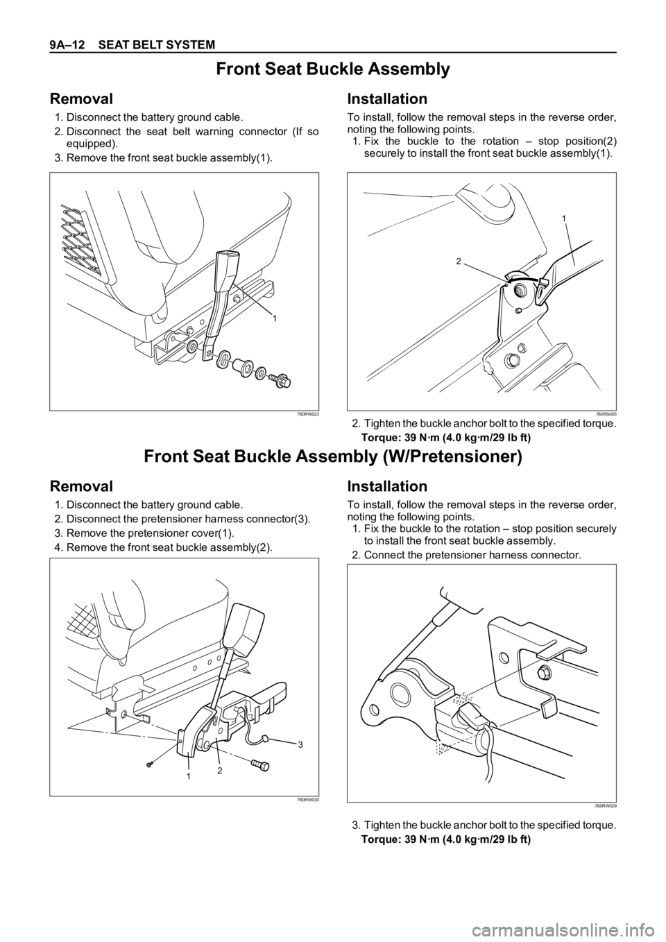
3. Remove the front seat buckle assembly(1).
Installation
To install, follow the removal steps in the reverse order,
noting the following points.
1. Fix the buckle to the rotation – stop position(2)
securely to install the front seat buckle assembly(1).
2. Tighten the buckle anchor bolt to the specified torque.
Torque: 39 Nꞏm (4.0 kgꞏm/29 lb ft)
1
760RW023
1
2
760RS005
Front Seat Buckle Assembly (W/Pretensioner)
Removal
1. Disconnect the battery ground cable.
2. Disconnect the pretensioner harness connector(3).
3. Remove the pretensioner cover(1).
4. Remove the front seat buckle assembly(2).
Installation
To install, follow the removal steps in the reverse order,
noting the following points.
1. Fix the buckle to the rotation – stop position securely
to install the front seat buckle assembly.
2. Connect the pretensioner harness connector.
3. Tighten the buckle anchor bolt to the specified torque.
Torque: 39 Nꞏm (4.0 kgꞏm/29 lb ft)
123
760RW030760RW029
Page 3453 of 6000
SUPPLEMENTAL RESTRAINT SYSTEM 9J–16
5. Remove passenger air bag assembly from vehicle.
Refer to “Passenger Air Bag Assembly Removal ” in
this Section 9J–3.
6. Clear a space on the ground approximately 183 cm
(six feet) in clearance where the fixture with attached
air bag assembly is to be placed for deployment. A
paved outdoor location where there is no activity is
preferred. If an outdoor location is not available, a
space on the shop floor where is no activity and
sufficient ventilation is recommended. Ensure that no
loose or flammable objects are within the deployment
area.
7. Place the 5–8840–2420–0 on the bench vice. This is
necessary to provide sufficient stabilization of the
fixture during deployment.
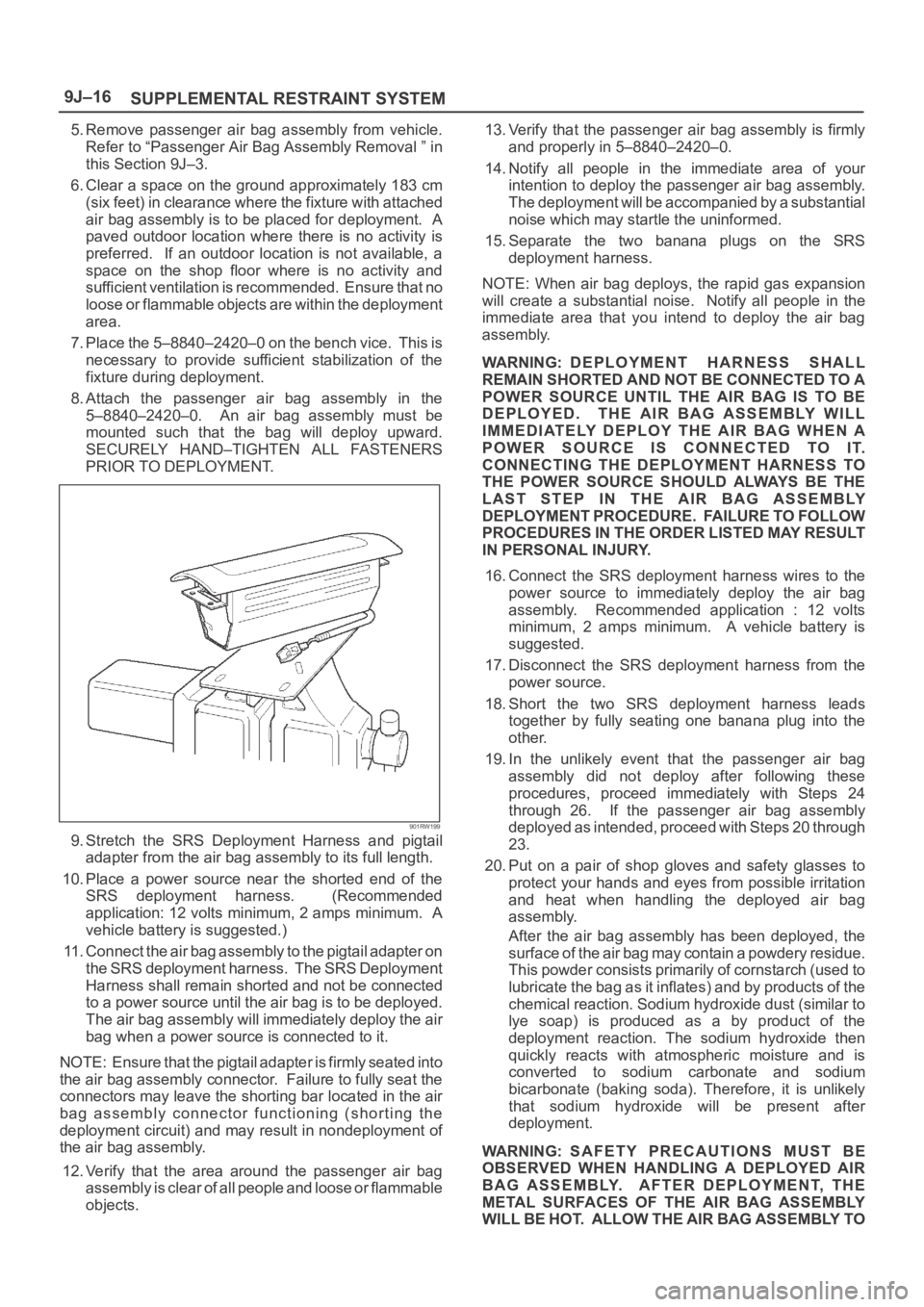
8. Attach the passenger air bag assembly in the
5–8840–2420–0. An air bag assembly must be
mounted such that the bag will deploy upward.
SECURELY HAND–TIGHTEN ALL FASTENERS
PRIOR TO DEPLOYMENT.
901RW199
9. Stretch the SRS Deployment Harness and pigtail
adapter from the air bag assembly to its full length.
10. Place a power source near the shorted end of the
SRS deployment harness. (Recommended
application: 12 volts minimum, 2 amps minimum. A
vehicle battery is suggested.)
11. Connect the air bag assembly to the pigtail adapter on
the SRS deployment harness. The SRS Deployment
Harness shall remain shorted and not be connected
to a power source until the air bag is to be deployed.
The air bag assembly will immediately deploy the air
bag when a power source is connected to it.
NOTE: Ensure that the pigtail adapter is firmly seated into
the air bag assembly connector. Failure to fully seat the
connectors may leave the shorting bar located in the air
bag assembly connector functioning (shorting the
deployment circuit) and may result in nondeployment of
the air bag assembly.
12. Verify that the area around the passenger air bag
assembly is clear of all people and loose or flammable
objects.13. Verify that the passenger air bag assembly is firmly
and properly in 5–8840–2420–0.
14. Notify all people in the immediate area of your
intention to deploy the passenger air bag assembly.
The deployment will be accompanied by a substantial
noise which may startle the uninformed.
15. Separate the two banana plugs on the SRS
deployment harness.
NOTE: When air bag deploys, the rapid gas expansion
will create a substantial noise. Notify all people in the
immediate area that you intend to deploy the air bag
assembly.
WARNING: DEPLOYMENT HARNESS SHALL
REMAIN SHORTED AND NOT BE CONNECTED TO A
POWER SOURCE UNTIL THE AIR BAG IS TO BE
DEPLOYED. THE AIR BAG ASSEMBLY WILL
IMMEDIATELY DEPLOY THE AIR BAG WHEN A
POWER SOURCE IS CONNECTED TO IT.
CONNECTING THE DEPLOYMENT HARNESS TO
THE POWER SOURCE SHOULD ALWAYS BE THE
LAST STEP IN THE AIR BAG ASSEMBLY
DEPLOYMENT PROCEDURE. FAILURE TO FOLLOW
PROCEDURES IN THE ORDER LISTED MAY RESULT
IN PERSONAL INJURY.
16. Connect the SRS deployment harness wires to the
power source to immediately deploy the air bag
assembly. Recommended application : 12 volts
minimum, 2 amps minimum. A vehicle battery is
suggested.
17. Disconnect the SRS deployment harness from the
power source.
18. Short the two SRS deployment harness leads
together by fully seating one banana plug into the
other.
19. In the unlikely event that the passenger air bag
assembly did not deploy after following these
procedures, proceed immediately with Steps 24
through 26. If the passenger air bag assembly
deployed as intended, proceed with Steps 20 through
23.
20. Put on a pair of shop gloves and safety glasses to
protect your hands and eyes from possible irritation
and heat when handling the deployed air bag
assembly.
After the air bag assembly has been deployed, the
surface of the air bag may contain a powdery residue.
Th is p ow de r con sis ts prim a r ily of c or n sta r ch ( u sed to
lubricate the bag as it inflates) and by products of the
chemical reaction. Sodium hydroxide dust (similar to
lye soap) is produced as a by product of the
deployment reaction. The sodium hydroxide then
quickly reacts with atmospheric moisture and is
converted to sodium carbonate and sodium
bicarbonate (baking soda). Therefore, it is unlikely
that sodium hydroxide will be present after
deployment.
WARNING: SAFETY PRECAUTIONS MUST BE
OBSERVED WHEN HANDLING A DEPLOYED AIR
BAG ASSEMBLY. AFTER DEPLOYMENT, THE
METAL SURFACES OF THE AIR BAG ASSEMBLY
WILL BE HOT. ALLOW THE AIR BAG ASSEMBLY TO
Page 3458 of 6000
SUPPLEMENTAL RESTRAINT SYSTEM9J–21
THROUGHOUT THIS ENTIRE DEPLOYMENT AND
DISPOSAL PROCEDURE.
9. Twist together one connector wire lead to one
deployment wire. The connection should be
mechanically secure.
10. Bend twisted connection made in the previous step
flat and wrap tightly with electrical tape to insulate and
secure.
11. Twist together, bend and tape the remaining
connector wire lead to the remaining deployment
wire.
12. Connect the deployment harness to the driver air bag
assembly, yellow 2–pin connector at the base of the
steering column. Route deployment harness out the
driver side of the vehicle.
WARNING: DEPLOYMENT WIRES SHALL REMAIN
SHORTED AND NOT BE CONNECTED TO A POWER
SOURCE UNTIL THE AIR BAG IS TO BE DEPLOYED.
THE AIR BAG ASSEMBLY WILL IMMEDIATELY
DEPLOY THE AIR BAG WHEN A POWER SOURCE IS
CONNECTED TO IT.
CONNECTING THE DEPLOYMENT WIRES TO THE
POWER SOURCE SHOULD ALWAYS BE THE FINAL
STEP IN THE AIR BAG ASSEMBLY DEPLOYMENT
PROCEDURE.
FAILURE TO FOLLOW PROCEDURES IN THE
ORDER LISTED COULD RESULT IN PERSONAL
INJURY.
13. Disconnect passenger air bag assembly, yellow 2–pin
connector located behind glove box assembly.
14. Cut the passenger air bag assembly harness
connector from the vehicle leaving at least 15 cm (six
inches) of wire at the connector.
15. Strip 13 mm (1/2 inch) of insulation from blue–white
and pink–blue wire lead of the connector.
16. Cut two 900 cm (30 feet) deployment wires from 0.8
mm
(18 gauge) or thicker multi–strand wire. These
wires will be used to fabricate the passenger
deployment harness.
17. Strip 13 mm (1/2 inch) of insulation from both ends of
the wires cut in the previous step.
18. Short the wires by twisting together one end from
each. Deployment wires shall remain shorted and not
be connected to a power source until the air bag is to
be deployed.
WARNING: FAILURE TO FOLLOW PROCEDURES IN
THE ORDER LISTED COULD RESULT IN PERSONAL
INJURY. NEVER CONNECT DEPLOYMENT WIRES
TO ANY POWER SOURCE BEFORE CONNECTING
DEPLOYMENT WIRES TO THE AIR BAG ASSEMBLY
LEADS. DEPLOYMENT WIRES SHALL REMAIN
SHORTED AND NOT BE CONNECTED TO A POWER
SOURCE UNTIL THE AIR BAG IS TO BE DEPLOYED.
THE AIR BAG ASSEMBLY WILL IMMEDIATELY
DEPLOY THE AIR BAG WHEN A POWER SOURCE IS
CONNECTED TO IT. WEAR SAFETY GLASSES
THROUGHOUT THIS ENTIRE DEPLOYMENT AND
DISPOSAL PROCEDURE.19. Twist together one connector wire lead to one
deployment wire. The connection should be
mechanically secure.
20. Bend twisted connection made in the previous step
flat and wrap tightly with electrical tape to insulate and
secure.
21. Twist together, bend and tape the remaining
connector wire lead to the remaining deployment
wire.
22. Connect the deployment harness to the passenger air
bag assembly, yellow 2–pin connector located behind
the glove box assembly. Route deployment harness
out the passenger side of the vehicle.
WARNING: DEPLOYMENT WIRES SHALL REMAIN
SHORTED AND NOT BE CONNECTED TO A POWER
SOURCE UNTIL THE AIR BAG IS TO BE DEPLOYED.
THE AIR BAG ASSEMBLY WILL IMMEDIATELY
DEPLOY THE AIR BAG WHEN A POWER SOURCE IS
CONNECTED TO IT. CONNECTING THE
DEPLOYMENT WIRES SHOULD ALWAYS BE THE
FINAL STEP IN THE AIR BAG ASSEMBLY
DEPLOYMENT PROCEDURE. FAILURE TO FOLLOW
PROCEDURES IN THE ORDER LISTED COULD
RESULT IN PERSONAL INJURY.
23. Verify that the inside of the vehicle and the area
surrounding the vehicle are clear of all people and
loose or flammable objects.
24. Stretch the driver and passenger deployment
harness to their full length.
25. Completely cover windshield area and front door
window openings with a drop cloth, blanket or similar
item. This reduces the possibility of injury due to
possible fragmentation of the vehicle’s glass or
interior.
26. Notify all people in the immediate area that you intend
to deploy the air bags. The deployment will be
accompanied by a substantial noise which may
startle the uninformed.
27. Separate the two ends of the driver deployment
harness wires.
WARNING: DEPLOYMENT WIRES SHALL REMAIN
SHORTED AND NOT BE CONNECTED TO A POWER
SOURCE UNTIL THE AIR BAG IS TO A POWER
SOURCE UNTIL THE AIR BAG IS TO BE DEPLOYED.
THE AIR BAG ASSEMBLY WILL IMMEDIATELY
DEPLOY THE AIR BAG WHEN A POWER SOURCE IS
CONNECTED TO IT. CONNECTING THE
DEPLOYMENT WIRES TO THE POWER SOURCE
SHOULD ALWAYS BE THE FINAL STEP IN THE AIR
BAG ASSEMBLY DEPLOYMENT PROCEDURE.
FAILURE TO FOLLOW PROCEDURES IN THE
ORDER LISTED COULD RESULT IN PERSONAL
INJURY.
NOTE: When the air bag deploys, the rapid gas
expansion will create a substantial noise. Notify all
people in the immediate area that you intend to deploy the
air bags.
Page 3496 of 6000
9J1–9
RESTRAINT CONTROL SYSTEM
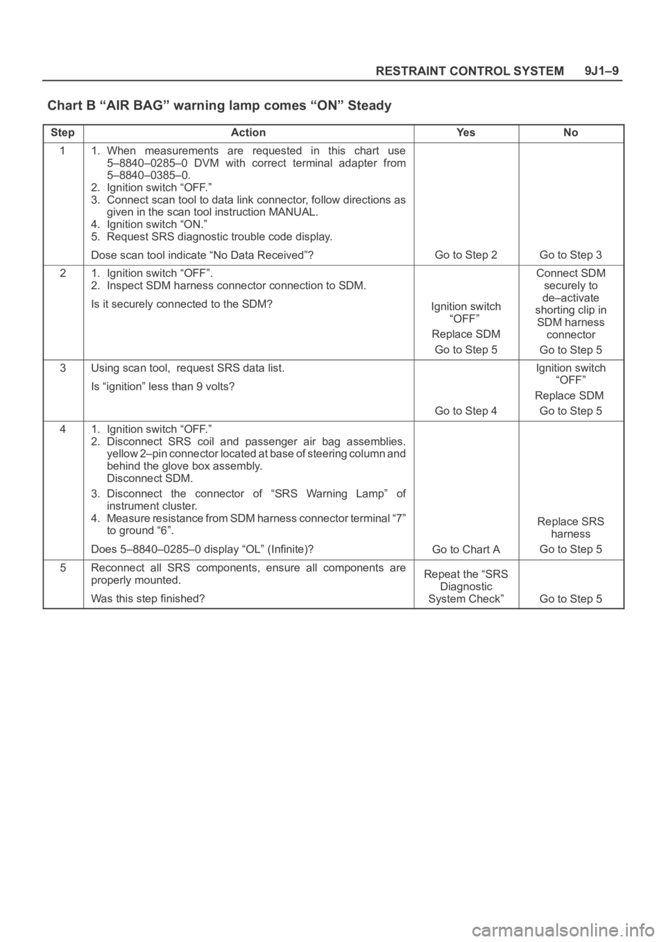
Chart B “AIR BAG” warning lamp comes “ON” Steady
StepActionYe sNo
11. When measurements are requested in this chart use
5–8840–0285–0 DVM with correct terminal adapter from
5–8840–0385–0.
2. Ignition switch “OFF.”
3. Connect scan tool to data link connector, follow directions as
given in the scan tool instruction MANUAL.
4. Ignition switch “ON.”
5. Request SRS diagnostic trouble code display.
Dose scan tool indicate “No Data Received”?
Go to Step 2Go to Step 3
21. Ignition switch “OFF”.
2. Inspect SDM harness connector connection to SDM.
Is it securely connected to the SDM?
Ignition switch
“OFF”
Replace SDM
Go to Step 5
Connect SDM
securely to
de–activate
shorting clip in
SDM harness
connector
Go to Step 5
3Using scan tool, request SRS data list.
Is “ignition” less than 9 volts?
Go to Step 4
Ignition switch
“OFF”
Replace SDM
Go to Step 5
41. Ignition switch “OFF.”
2. Disconnect SRS coil and passenger air bag assemblies.
yellow 2–pin connector located at base of steering column and
behind the glove box assembly.
Disconnect SDM.
3. Disconnect the connector of “SRS Warning Lamp” of
instrument cluster.
4. Measure resistance from SDM harness connector terminal “7”
to ground “6”.
Does 5–8840–0285–0 display “OL” (Infinite)?
Go to Chart A
Replace SRS
harness
Go to Step 5
5Reconnect all SRS components, ensure all components are
properly mounted.
Was this step finished?Repeat the “SRS
Diagnostic
System Check”
Go to Step 5
Page 3556 of 6000
10A–5
CRUISE CONTROL SYSTEM
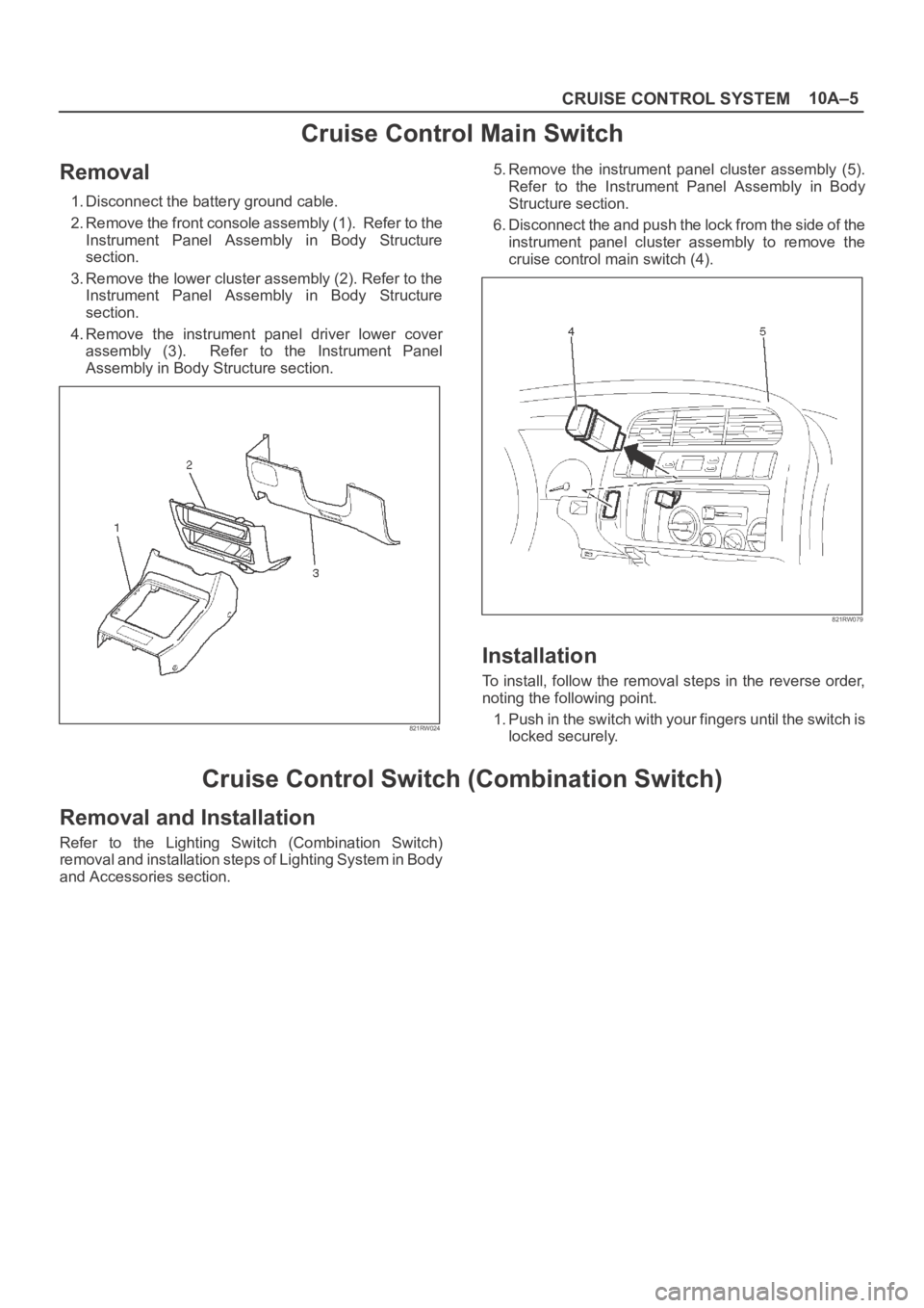
Cruise Control Main Switch
Removal
1. Disconnect the battery ground cable.
2. Remove the front console assembly (1). Refer to the
Instrument Panel Assembly in Body Structure
section.
3. Remove the lower cluster assembly (2). Refer to the
Instrument Panel Assembly in Body Structure
section.
4. Remove the instrument panel driver lower cover
assembly (3). Refer to the Instrument Panel
Assembly in Body Structure section.
821RW024
5. Remove the instrument panel cluster assembly (5).
Refer to the Instrument Panel Assembly in Body
Structure section.
6. Disconnect the and push the lock from the side of the
instrument panel cluster assembly to remove the
cruise control main switch (4).
821RW079
Installation
To install, follow the removal steps in the reverse order,
noting the following point.
1. Push in the switch with your fingers until the switch is
locked securely.
Cruise Control Switch (Combination Switch)
Removal and Installation
Refer to the Lighting Switch (Combination Switch)
removal and installation steps of Lighting System in Body
and Accessories section.
Page 3569 of 6000
PAGE BACK PAGE NEXT
THIS MALUAL INCLUDES THE FOLLOWING SECTIONS:
SECTION No. CONTRNTS
8A LIGHTING SYSTEM
8B WIPER / WASHER SYSTEM
8C ENTERTAINMENT
8D WIRING SYSTEM
8E METER AND GAUGE
8F BODY STRUCTURE
8G SEATS
8H SECURITY AND LOCKS
8I SUN ROOF/CONVERTIBLE TOP
8J EXTERIOR / INTERIOR TRIM
HOME
8A
8B
8C
8D
8E
8F
8G
8H
8I
8J
Page 3781 of 6000
COMPRESSOR SHAFT SEAL
Service Precaution
When replacing the shaft seal assembly, pressure relief
valve or control switches, it will be necessary to recover
the refrigerant. Other than clutch repair procedures, the
same holds true for any disassembly of the compressor.
A clean workbench covered with a sheet of clean
paper, and a place (clean trays, etc) for all parts being
removed and replaced is important, as is the use of
proper clean service tools.
CAUTION: Any attempt to use makeshift or
inadequate service tools or equipment may result
in damage and/or improper compressor operation.
All parts required for servicing the internal compressor
are protected by a preservative process and packaged
in a manner which will eliminate the necessity of
cleaning, washing or flushing of the parts. The parts
can be used in the internal assembly just as they are
removed from the service package. Seals and
protective packaging should be left intact until just
prior to installation.
If the compressor rear head, front head or cylinder and
shaft assembly is to be serviced or replaced, the oil in
the compressor must be drained, measured, recorded
and replaced.
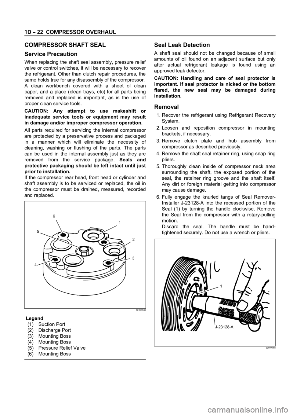
Legend
(1) Suction Port
(2) Discharge Port
(3) Mounting Boss
(4) Mounting Boss
(5) Pressure Relief Valve
(6) Mounting Boss
Seal Leak Detection
A shaft seal should not be changed because of small
amounts of oil found on an adjacent surface but only
after actual refrigerant leakage is found using an
approved leak detector.
CAUTION: Handling and care of seal protector is
important. If seal protector is nicked or the bottom
flared, the new seal may be damaged during
installation.
Removal
1. Recover the refrigerant using Refrigerant Recovery
System.
2. Loosen and reposition compressor in mounting
brackets, if necessary.
3. Remove clutch plate and hub assembly from
compressor as described previously.
4. Remove the shaft seal retainer ring, using snap ring
pliers.
5. Thoroughly clean inside of compressor neck area
surrounding the shaft, the exposed portion of the
seal, the retainer ring groove and the shaft itself.
Any dirt or foreign material getting into compressor
may cause damage.
6. Fully engage the knurled tangs of Seal Remover-
Installer J-23128-A into the recessed portion of the
Seal (1) by turning the handle clockwise. Remove
the Seal from the compressor with a rotary-pulling
motion.
Discard the seal. The handle must be hand-
tightened securely. Do not use a wrench or pliers.
1
2
3
456
871RW006
J-23128-A1
901RW008
Page 3964 of 6000
DIFFERENTIAL (FRONT) 4A1–24
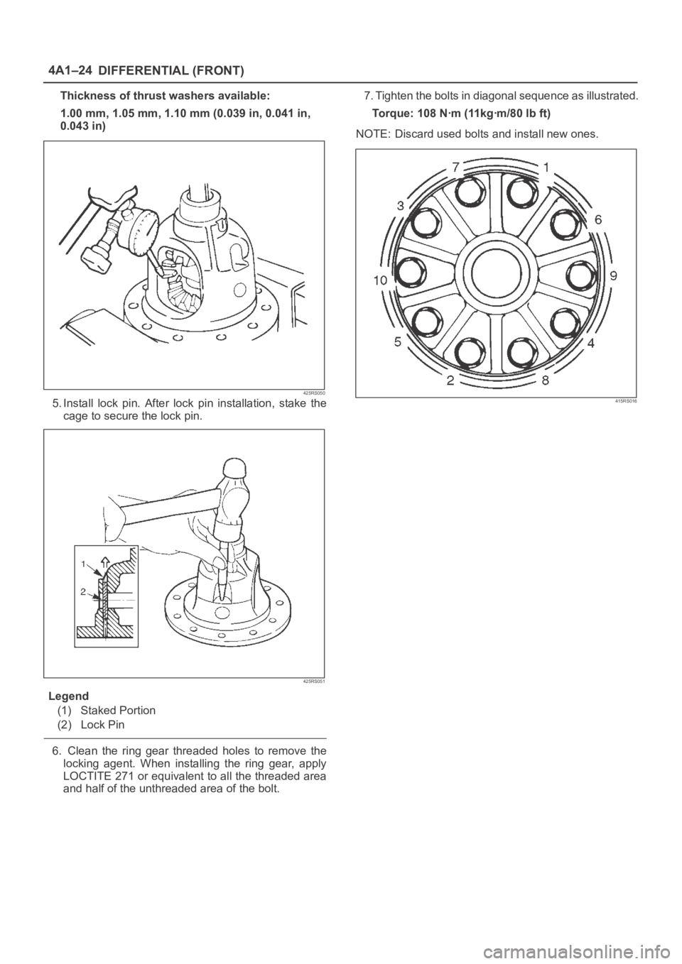
Thickness of thrust washers available:
1.00 mm, 1.05 mm, 1.10 mm (0.039 in, 0.041 in,
0.043 in)
425RS050
5. Install lock pin. After lock pin installation, stake the
cage to secure the lock pin.
425RS051
Legend
(1) Staked Portion
(2) Lock Pin
6. Clean the ring gear threaded holes to remove the
locking agent. When installing the ring gear, apply
LOCTITE 271 or equivalent to all the threaded area
and half of the unthreaded area of the bolt.7. Tighten the bolts in diagonal sequence as illustrated.
Torque: 108 Nꞏm (11kgꞏm/80 lb ft)
NOTE: Discard used bolts and install new ones.
415RS016