ECU OPEL FRONTERA 1998 Workshop Manual
[x] Cancel search | Manufacturer: OPEL, Model Year: 1998, Model line: FRONTERA, Model: OPEL FRONTERA 1998Pages: 6000, PDF Size: 97 MB
Page 3996 of 6000
DIFFERENTIAL (REAR 220mm)
4A2A–27
Thickness of thrust washers available:
0.80 mm, 0.90 mm, 1.00 mm 1.10 mm, 1.20 mm,
1.30 mm (0.031 in, 0.035 in, 0.039 in,0.043 in,
0.047 in, 0.051 in)
425RS050
5. Install lock pin. After lock pin installation, stake the
cage to secure the lock pin.
425RS051
Legend
(1) Staked Portion
(2) Lock Pin
6. Clean the ring gear threaded holes to remove the
locking agent. When installing the ring gear, apply
LOCTITE 271 or equivalent to all the threaded area
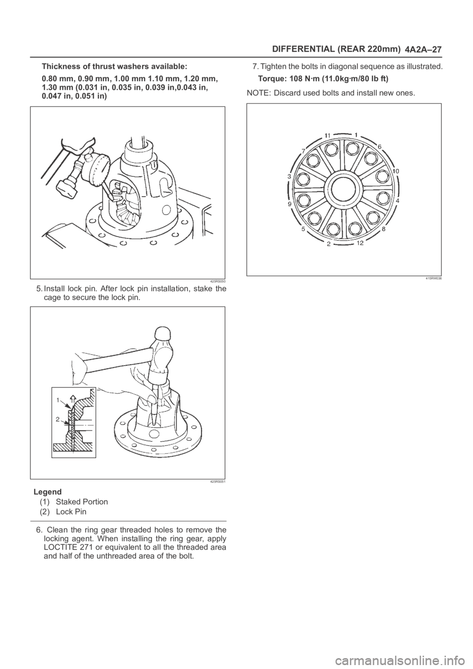
and half of the unthreaded area of the bolt.7. Tighten the bolts in diagonal sequence as illustrated.
Torque: 108 Nꞏm (11.0kgꞏm/80 lb ft)
NOTE: Discard used bolts and install new ones.
415RW036
Page 4085 of 6000
DRIVE LINE CONTROL SYSTEM (TOD) 4B2–2
General Description
C07RW014–1
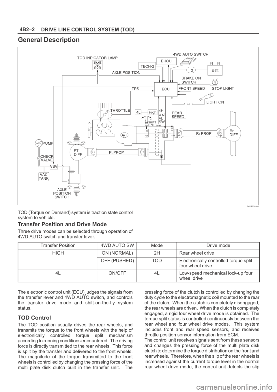
TOD (Torque on Demand) system is traction state control
system to vehicle.
Transfer Position and Drive Mode
Three drive modes can be selected through operation of
4WD AUTO switch and transfer lever.
Transfer Position
4WD AUTO SWModeDrive mode
HIGHON (NORMAL)2HRear wheel drive
OFF (PUSHED)TODElectronically controlled torque split
four wheel drive
4LON/OFF4LLow-speed mechanical lock-up four
wheel drive
The electronic control unit (ECU) judges the signals from
the transfer lever and 4WD AUTO switch, and controls
the transfer drive mode and shift-on-the-fly system
status.
TOD Control
The TOD position usually drives the rear wheels, and
transmits the torque to the front wheels with the help of
electronically controlled torque split mechanism
according to running conditions encountered. The driving
force is directly transmitted to the rear wheels. This force
is split by the transfer and delivered to the front wheels.
The magnitude of the torque transmitted to the front
wheels is controlled by changing the pressing force of the
multi plate disk clutch built in the transfer unit. Thepressing force of the clutch is controlled by changing the
duty cycle to the electromagnetic coil mounted to the rear
of the clutch. When the clutch is completely disengaged,
the rear wheels are driven. When the clutch is completely
engaged, a rigid four wheel drive mode is obtained. The
torque split status is controlled continuously between the
rear wheel and four wheel drive modes. This system
includes front and rear speed sensors, and receives
throttle position sensor information from ECM.
The control unit receives signals sent from these sensors
and changes the pressing force of the multi plate disk
clutch to determine the torque distribution on the front and
rear wheels. Therefore, when the slip of the rear wheels is
increased against the current torque level in the normal
rear wheel drive mode, the control unit detects the slip
Page 4090 of 6000
4B2–7 DRIVE LINE CONTROL SYSTEM (TOD)
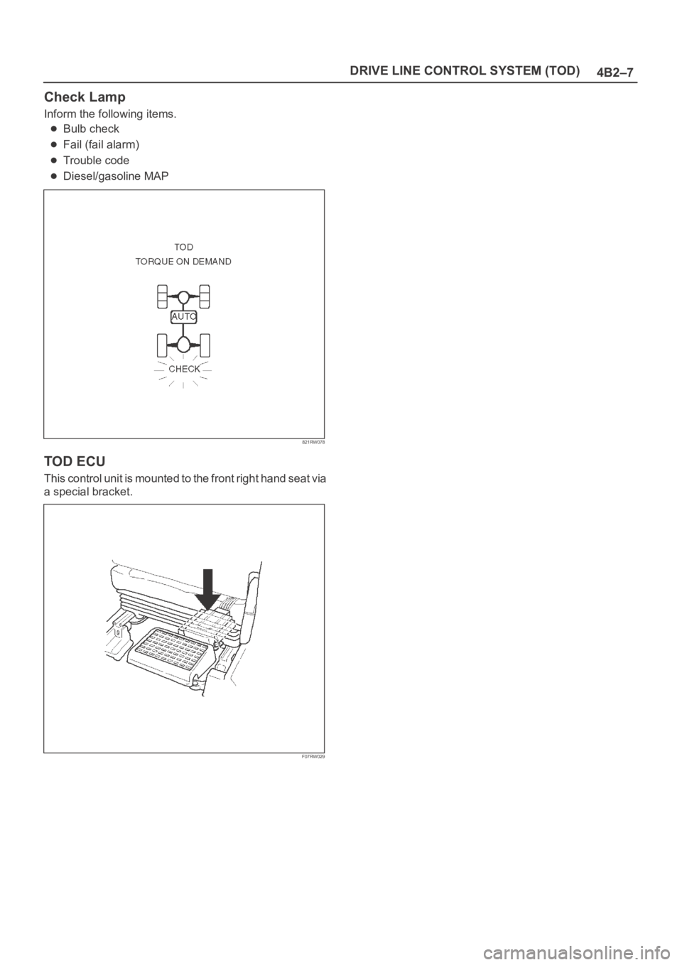
Check Lamp
Inform the following items.
Bulb check
Fail (fail alarm)
Trouble code
Diesel/gasoline MAP
821RW078
TOD ECU
This control unit is mounted to the front right hand seat via
a special bracket.
F07RW029
Page 4094 of 6000
4B2–11 DRIVE LINE CONTROL SYSTEM (TOD)
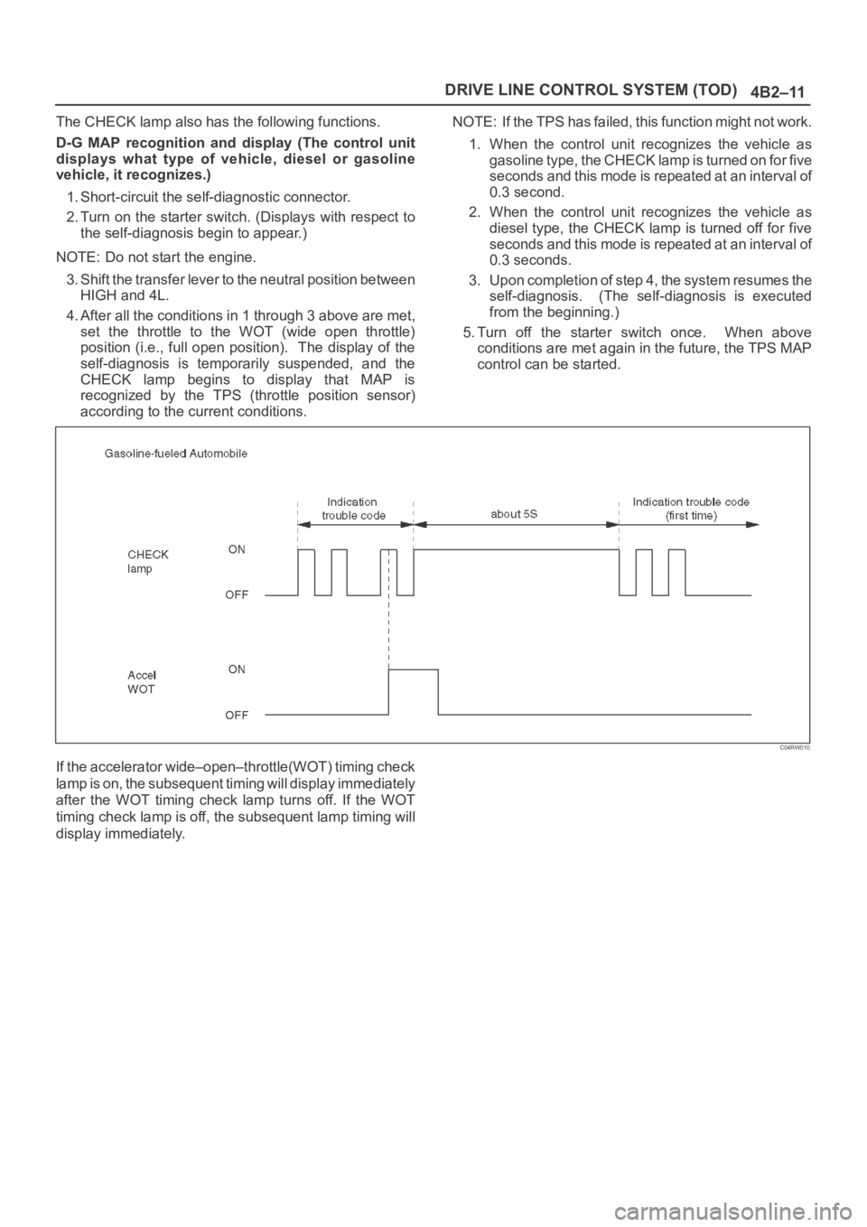
The CHECK lamp also has the following functions.
D-G MAP recognition and display (The control unit
displays what type of vehicle, diesel or gasoline
vehicle, it recognizes.)
1. Short-circuit the self-diagnostic connector.
2. Turn on the starter switch. (Displays with respect to
the self-diagnosis begin to appear.)
NOTE: Do not start the engine.
3. Shift the transfer lever to the neutral position between
HIGH and 4L.
4. After all the conditions in 1 through 3 above are met,
set the throttle to the WOT (wide open throttle)
position (i.e., full open position). The display of the
self-diagnosis is temporarily suspended, and the
CHECK lamp begins to display that MAP is
recognized by the TPS (throttle position sensor)
according to the current conditions.NOTE: If the TPS has failed, this function might not work.
1. When the control unit recognizes the vehicle as
gasoline type, the CHECK lamp is turned on for five
seconds and this mode is repeated at an interval of
0.3 second.
2. When the control unit recognizes the vehicle as
diesel type, the CHECK lamp is turned off for five
seconds and this mode is repeated at an interval of
0.3 seconds.
3. Upon completion of step 4, the system resumes the
self-diagnosis. (The self-diagnosis is executed
from the beginning.)
5. Turn off the starter switch once. When above
conditions are met again in the future, the TPS MAP
control can be started.
C04RW010
If the accelerator wide–open–throttle(WOT) timing check
lamp is on, the subsequent timing will display immediately
after the WOT timing check lamp turns off. If the WOT
timing check lamp is off, the subsequent lamp timing will
display immediately.
Page 4098 of 6000
4B2–15 DRIVE LINE CONTROL SYSTEM (TOD)
How to Clear The Trouble Code
The trouble codes saved to the control unit can be deleted
by the following procedure if the starter switch is being in
the OFF position.
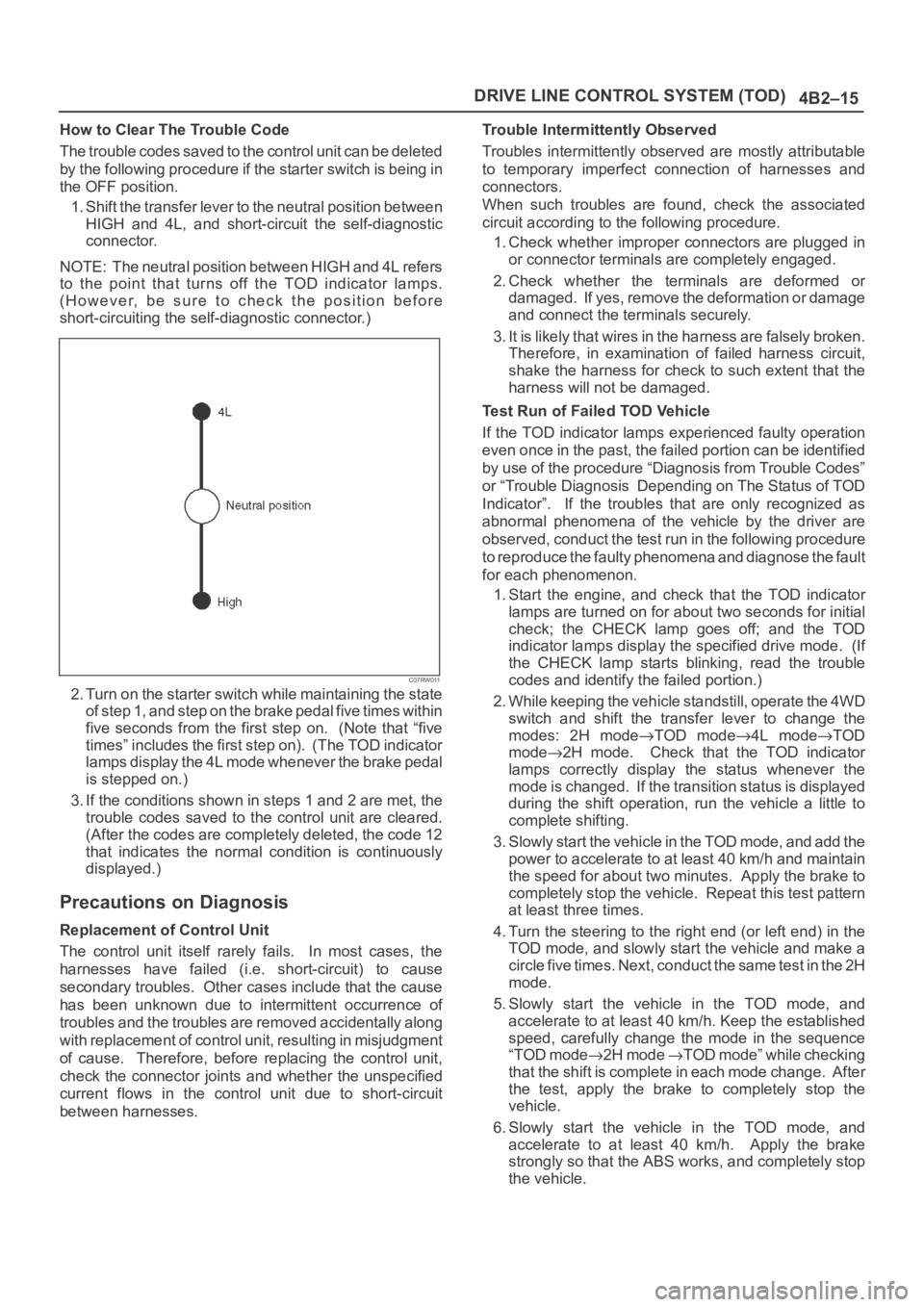
1. Shift the transfer lever to the neutral position between
HIGH and 4L, and short-circuit the self-diagnostic
connector.
NOTE: The neutral position between HIGH and 4L refers
to the point that turns off the TOD indicator lamps.
(However, be sure to check the position before
short-circuiting the self-diagnostic connector.)
C07RW011
2. Turn on the starter switch while maintaining the state
of step 1, and step on the brake pedal five times within
five seconds from the first step on. (Note that “five
times” includes the first step on). (The TOD indicator
lamps display the 4L mode whenever the brake pedal
is stepped on.)
3. If the conditions shown in steps 1 and 2 are met, the
trouble codes saved to the control unit are cleared.
(After the codes are completely deleted, the code 12
that indicates the normal condition is continuously
displayed.)
Precautions on Diagnosis
Replacement of Control Unit
The control unit itself rarely fails. In most cases, the
harnesses have failed (i.e. short-circuit) to cause
secondary troubles. Other cases include that the cause
has been unknown due to intermittent occurrence of
troubles and the troubles are removed accidentally along
with replacement of control unit, resulting in misjudgment
of cause. Therefore, before replacing the control unit,
check the connector joints and whether the unspecified
current flows in the control unit due to short-circuit
between harnesses.Trouble Intermittently Observed
Troubles intermittently observed are mostly attributable
to temporary imperfect connection of harnesses and
connectors.
When such troubles are found, check the associated
circuit according to the following procedure.
1. Check whether improper connectors are plugged in
or connector terminals are completely engaged.
2. Check whether the terminals are deformed or
damaged. If yes, remove the deformation or damage
and connect the terminals securely.
3. It is likely that wires in the harness are falsely broken.
Therefore, in examination of failed harness circuit,
shake the harness for check to such extent that the
harness will not be damaged.
Test Run of Failed TOD Vehicle
If the TOD indicator lamps experienced faulty operation
even once in the past, the failed portion can be identified
by use of the procedure “Diagnosis from Trouble Codes”
or “Trouble Diagnosis Depending on The Status of TOD
Indicator”. If the troubles that are only recognized as
abnormal phenomena of the vehicle by the driver are
observed, conduct the test run in the following procedure
to reproduce the faulty phenomena and diagnose the fault
for each phenomenon.
1. Start the engine, and check that the TOD indicator
lamps are turned on for about two seconds for initial
check; the CHECK lamp goes off; and the TOD
indicator lamps display the specified drive mode. (If
the CHECK lamp starts blinking, read the trouble
codes and identify the failed portion.)
2. While keeping the vehicle standstill, operate the 4WD
switch and shift the transfer lever to change the
modes: 2H mode
TOD mode4L modeTOD
mode
2H mode. Check that the TOD indicator
lamps correctly display the status whenever the
mode is changed. If the transition status is displayed
during the shift operation, run the vehicle a little to
complete shifting.
3. Slowly start the vehicle in the TOD mode, and add the
power to accelerate to at least 40 km/h and maintain
the speed for about two minutes. Apply the brake to
completely stop the vehicle. Repeat this test pattern
at least three times.
4. Turn the steering to the right end (or left end) in the
TOD mode, and slowly start the vehicle and make a
c i r c l e f i v e t i m e s . N e x t , c o n d u c t t h e s a m e t e s t i n t h e 2 H
mode.
5. Slowly start the vehicle in the TOD mode, and
accelerate to at least 40 km/h. Keep the established
speed, carefully change the mode in the sequence
“TOD mode
2H mode TOD mode” while checking
that the shift is complete in each mode change. After
the test, apply the brake to completely stop the
vehicle.
6. Slowly start the vehicle in the TOD mode, and
accelerate to at least 40 km/h. Apply the brake
strongly so that the ABS works, and completely stop
the vehicle.
Page 4119 of 6000
DRIVE LINE CONTROL SYSTEM (TOD) 4B2–36
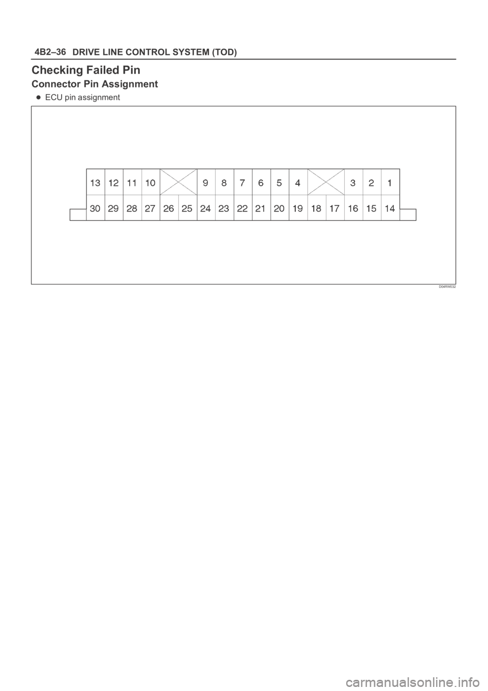
Checking Failed Pin
Connector Pin Assignment
ECU pin assignment
D04RW032
Page 4122 of 6000
4B2–39 DRIVE LINE CONTROL SYSTEM (TOD)
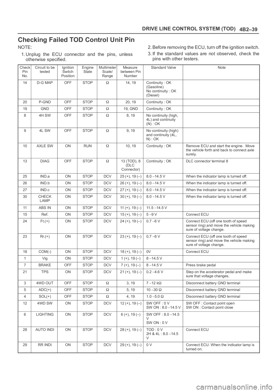
Checking Failed TOD Control Unit Pin
NOTE:
1. Unplug the ECU connector and the pins, unless
otherwise specified.2. Before removing the ECU, turn off the ignition switch.
3. If the standard values are not observed, check the
pins with other testers.
Check
Pin
No.Circuit to be
testedIgnition
Switch
PositionEngine
StateMultimeter
Scale/
RangeMeasure
between Pin
NumberStandard ValveNote
14D-G MAPOFFSTOP14, 19Continuity : OK
(Gasoline)
No continuity : OK
(Diesel)
20P-GNDOFFSTOP20, 19Continuity : OK
19GNDOFFSTOP19, GNDContinuity : OK
84H SWOFFSTOP8, 19No continuity (high,
4L) and continuity
(N) : OK
94L SWOFFSTOP9, 19No continuity (high)
and continuity (4L,
N) : OK
10AXLE SWONRUN10, 19Continuity : OKRemove ECU and start the engine. Move
the vehicle forth and back to connect axle
surely.
13DIAGOFFSTOP13 (TOD), 8
(DLC
Connector)Continuity : OKDLC connector terminal 8
25IND.aONSTOPDCV25 (+), 19 (–)8.0 14.5 VWhen the indicator lamp is turned off.
26IND.bONSTOPDCV26 (+), 19 (–)8.0 14.5 VWhen the indicator lamp is turned off.
27IND.cONSTOPDCV27 (+), 19 (–)8.0 14.5 VWhen the indicator lamp is turned off.
30CHECK
LAMPONSTOPDCV30 (+), 19 (–)8.0 14.5 VWhen the indicator lamp is turned off.
11ABS INONSTOPDCV11 (+), 19 (–)11 . 5 14.5 V
15Ref.ONSTOPDCV15 (+), 19 (–)5 9 VConnect ECU
24Ft.(+)ONSTOPDCV24 (+), 19 (–)0.7 6 VConnect ECU (off one tooth of speed
sensor ring) and move the vehicle making
sure of voltage change.
23Rr.(+)ONSTOPDCV23 (+), 19 (–)0.7 6 VConnect ECU (off one tooth of speed
sensor ring) and move the vehicle making
sure of voltage change.
18COM(-)ONSTOPDCV18 (+), 19 (–)0VConnect ECU
1VigONSTOPDCV1 (+), 19 (–)8 14.5 V
7BRAKEOFFSTOPDCV7 (+), 19 (–)8 14.5 VPress brake pedal
21TPSONSTOPDCV21 (+), 19 (–)0.2 4.6 VStep on the accelerator pedal and make
sure that voltage changes.
34WD OUTOFFSTOP3, 197 12 kDisconnect battery GND terminal
5ADC(+)OFFSTOP5, 1910 30 Disconnect battery GND terminal
4SOL(+)OFFSTOP4, 191.0 5.0 Disconnect battery GND terminal
124WD SWONSTOPDCV12 (+), 19 (–)SW OFF : 0 V
SW ON : 8.0 14.5 VSW OFF : Contact point open
SW ON : Contact point close
6LIGHTINGONSTOPDCV6 (+), 19 (–)SW OFF : 8.0 14.5
V
SW ON : 0 V
28AUTO INDIONSTOPDCV28 (+), 19 (–)TOD : 0 V
2H & 4L : 8.0 14.5
VConnect ECU
29RR INDIONSTOPDCV29 (+), 19 (–)0 VConnect ECU. When the indicator lamp is
turned on.
Page 4126 of 6000
4B2–43 DRIVE LINE CONTROL SYSTEM (TOD)
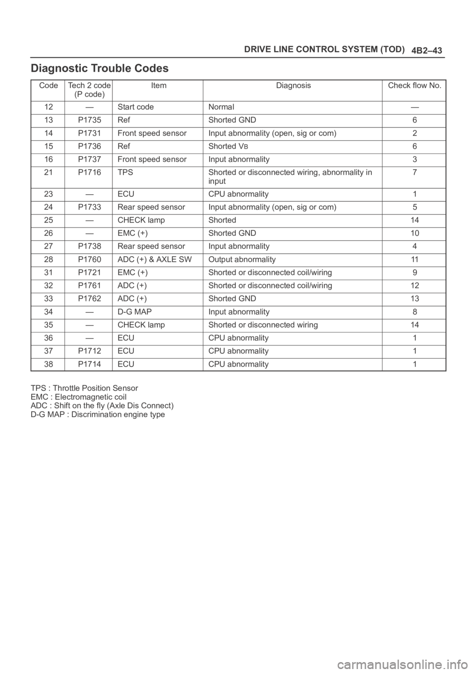
Diagnostic Trouble Codes
CodeTe c h 2 c o d e
(P code)ItemDiagnosisCheck flow No.
12—Start codeNormal—
13P1735RefShorted GND6
14P1731Front speed sensorInput abnormality (open, sig or com)2
15P1736RefShorted VB6
16P1737Front speed sensorInput abnormality3
21P1716TPSShorted or disconnected wiring, abnormality in
input7
23—ECUCPU abnormality1
24P1733Rear speed sensorInput abnormality (open, sig or com)5
25—CHECK lampShorted14
26—EMC (+)Shorted GND10
27P1738Rear speed sensorInput abnormality4
28P1760ADC (+) & AXLE SWOutput abnormality11
31P1721EMC (+)Shorted or disconnected coil/wiring9
32P1761ADC (+)Shorted or disconnected coil/wiring12
33P1762ADC (+)Shorted GND13
34—D-G MAPInput abnormality8
35—CHECK lampShorted or disconnected wiring14
36—ECUCPU abnormality1
37P1712ECUCPU abnormality1
38P1714ECUCPU abnormality1
TPS : Throttle Position Sensor
EMC : Electromagnetic coil
ADC : Shift on the fly (Axle Dis Connect)
D-G MAP : Discrimination engine type
Page 4127 of 6000
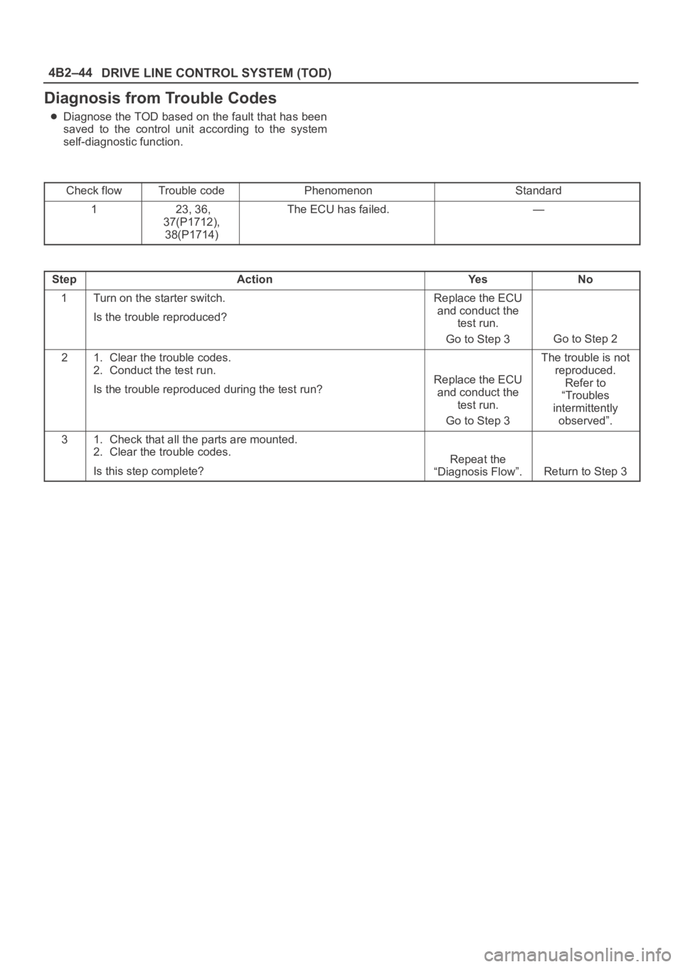
DRIVE LINE CONTROL SYSTEM (TOD) 4B2–44
Diagnosis from Trouble Codes
Diagnose the TOD based on the fault that has been
saved to the control unit according to the system
self-diagnostic function.
Check flow
Trouble codePhenomenonStandard
1 23, 36,
37(P1712),
38(P1714)The ECU has failed.—
StepActionYe sNo
1Turn on the starter switch.
Is the trouble reproduced?Replace the ECU
and conduct the
test run.
Go to Step 3
Go to Step 2
21. Clear the trouble codes.
2. Conduct the test run.
Is the trouble reproduced during the test run?
Replace the ECU
and conduct the
test run.
Go to Step 3
The trouble is not
reproduced.
Refer to
“Troubles
intermittently
observed”.
31. Check that all the parts are mounted.
2. Clear the trouble codes.
Is this step complete?
Repeat the
“Diagnosis Flow”.
Return to Step 3
Page 4129 of 6000
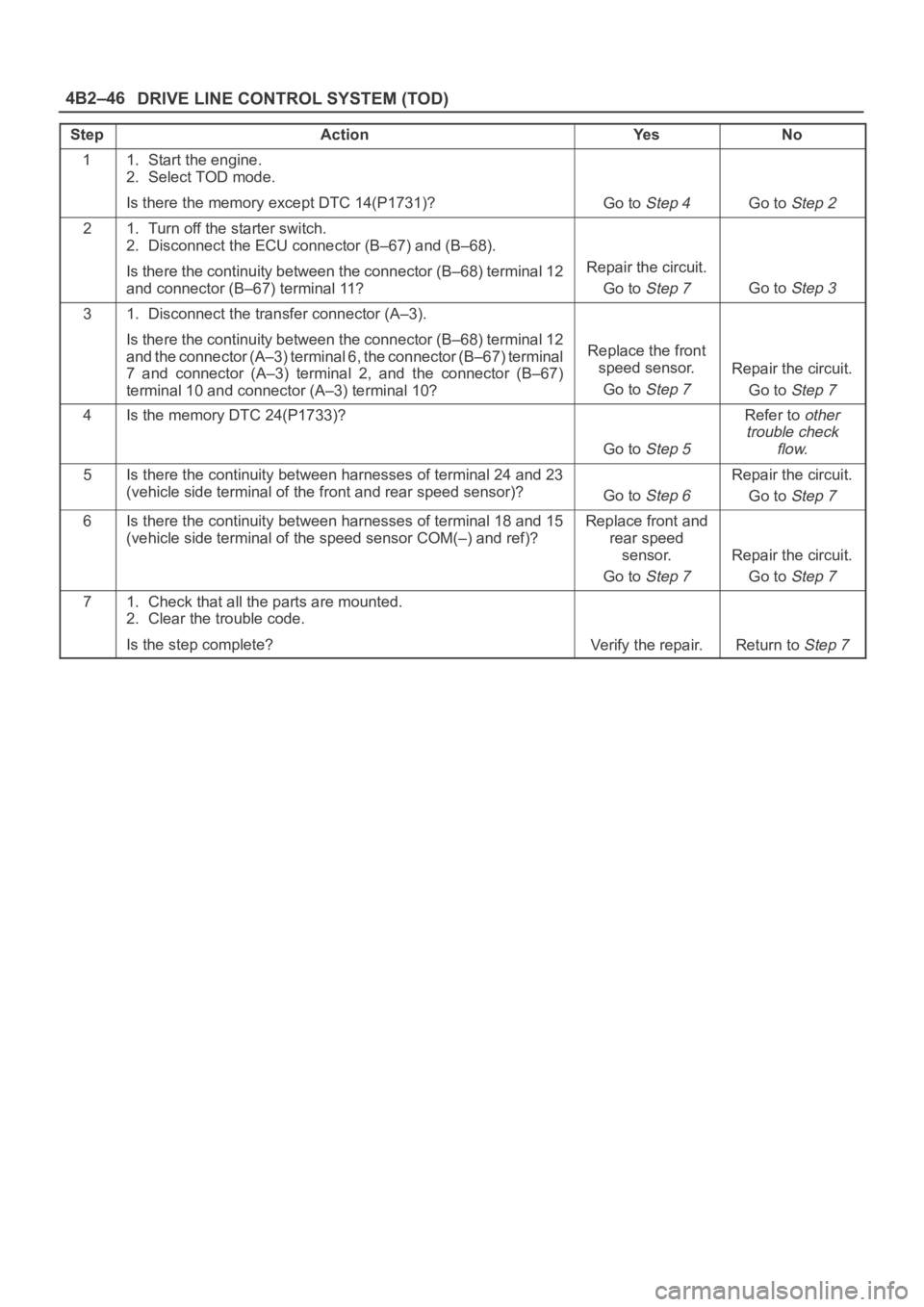
DRIVE LINE CONTROL SYSTEM (TOD) 4B2–46
StepActionYe sNo
11. Start the engine.
2. Select TOD mode.
Is there the memory except DTC 14(P1731)?
Go to Step 4Go to Step 2
21. Turn off the starter switch.
2. Disconnect the ECU connector (B–67) and (B–68).
Is there the continuity between the connector (B–68) terminal 12
and connector (B–67) terminal 11?
Repair the circuit.
Go to
Step 7Go to Step 3
31. Disconnect the transfer connector (A–3).
Is there the continuity between the connector (B–68) terminal 12
and the connector (A–3) terminal 6, the connector (B–67) terminal
7 and connector (A–3) terminal 2, and the connector (B–67)
terminal 10 and connector (A–3) terminal 10?
Replace the front
speed sensor.
Go to
Step 7
Repair the circuit.
Go to
Step 7
4Is the memory DTC 24(P1733)?
Go to Step 5
Refer to other
trouble check
flow.
5Is there the continuity between harnesses of terminal 24 and 23
(vehicle side terminal of the front and rear speed sensor)?
Go to Step 6
Repair the circuit.
Go to
Step 7
6Is there the continuity between harnesses of terminal 18 and 15
(vehicle side terminal of the speed sensor COM(–) and ref)?Replace front and
rear speed
sensor.
Go to
Step 7
Repair the circuit.
Go to
Step 7
71. Check that all the parts are mounted.
2. Clear the trouble code.
Is the step complete?
Verify the repair.Return to Step 7