Back OPEL FRONTERA 1998 Workshop Manual
[x] Cancel search | Manufacturer: OPEL, Model Year: 1998, Model line: FRONTERA, Model: OPEL FRONTERA 1998Pages: 6000, PDF Size: 97 MB
Page 2586 of 6000

ENTERTAINMENT8C–3
Digital Clock
Removal
1. Disconnect the battery ground cable.
2. Remove the front console assembly(1).
Refer to the Instrument Panel Assembly in Body
Structure section.
3. Remove the lower cluster assembly(2).
Refer to the Instrument Panel Assembly in Body
Structure section.
4. Remove the instrument panel driver lower cover
assembly(3).
Refer to the Instrument Panel Assembly in Body
Structure section.
821RW024
5. Remove the instrument panel cluster assembly(4).
Refer to the Instrument Panel Assembly in Body
Structure section.
6. Disconnect the connector and push the lock from the
back side of the instrument panel cluster assembly to
remove the digital clock(5).
821RW034
Installation
To install, follow the removal steps in the reverse order,
noting the following point.
1. Push in the switch with your fingers until it locks
securely.
Page 2601 of 6000

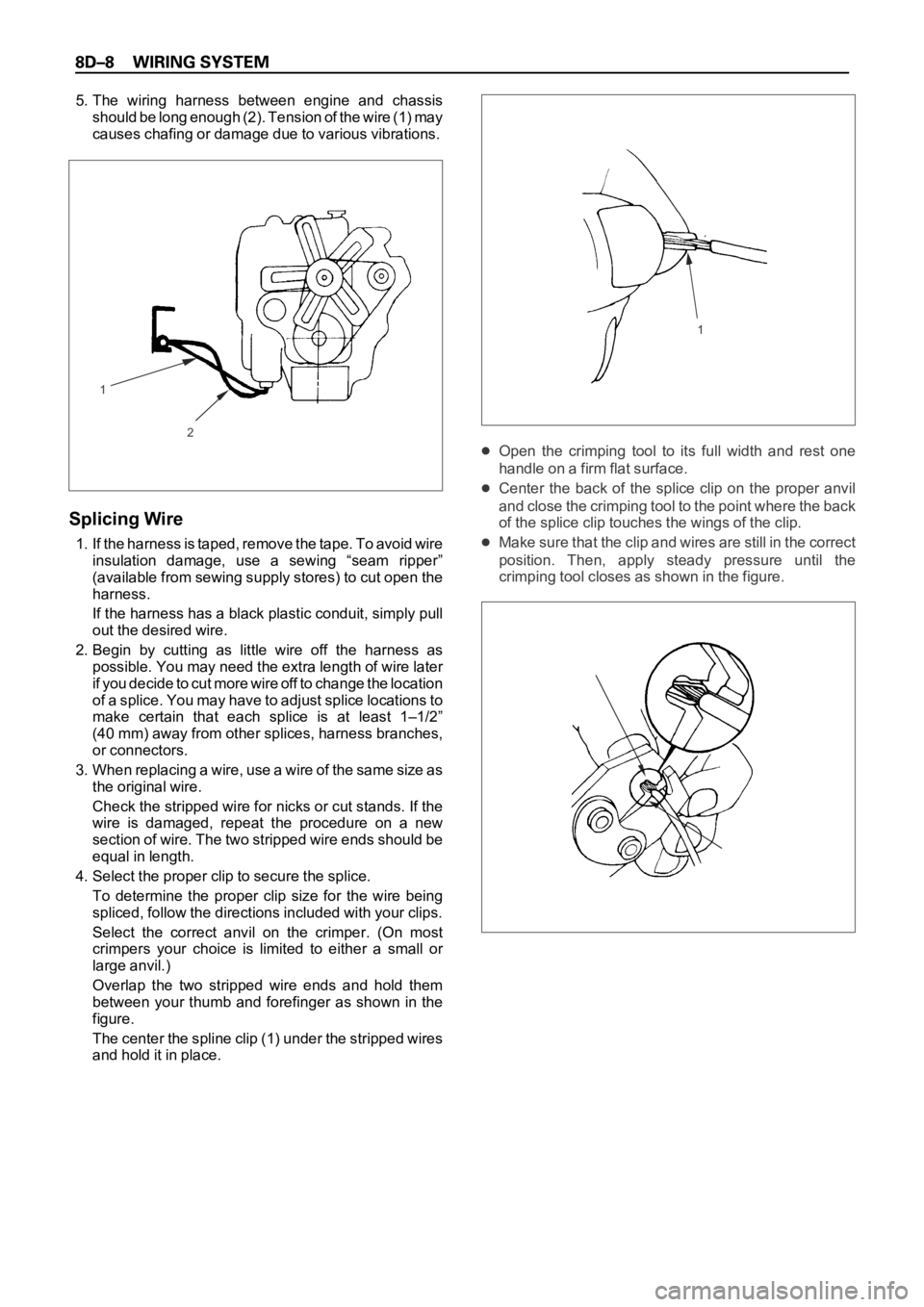
5. The wiring harness between engine and chassis
should be long enough (2). Tension of the wire (1) may
causes chafing or damage due to various vibrations.
Splicing Wire
1. If the harness is taped, remove the tape. To avoid wire
insulation damage, use a sewing “seam ripper”
(available from sewing supply stores) to cut open the
harness.
If the harness has a black plastic conduit, simply pull
out the desired wire.
2. Begin by cutting as little wire off the harness as
possible. You may need the extra length of wire later
if you decide to cut more wire off to change the location
of a splice. You may have to adjust splice locations to
make certain that each splice is at least 1–1/2”
(40 mm) away from other splices, harness branches,
or connectors.
3 . W h e n r e p l a c i n g a w i r e , u s e a w i r e o f t h e s a m e s i z e a s
the original wire.
Check the stripped wire for nicks or cut stands. If the
wire is damaged, repeat the procedure on a new
section of wire. The two stripped wire ends should be
equal in length.
4. Select the proper clip to secure the splice.
To determine the proper clip size for the wire being
spliced, follow the directions included with your clips.
Select the correct anvil on the crimper. (On most
crimpers your choice is limited to either a small or
large anvil.)
Overlap the two stripped wire ends and hold them
between your thumb and forefinger as shown in the
figure.
The center the spline clip (1) under the stripped wires
and hold it in place.
Open the crimping tool to its full width and rest one
handle on a firm flat surface.
Center the back of the splice clip on the proper anvil
and close the crimping tool to the point where the back
of the splice clip touches the wings of the clip.
Make sure that the clip and wires are still in the correct
position. Then, apply steady pressure until the
crimping tool closes as shown in the figure.
2
11
Page 2602 of 6000

Before crimping the ends of the clip (1), be sure that:
The wires extend beyond the clip in each direction.
No strands of wire are cut loose, and
No insulation is caught under the clip.
Crimp the splice again, once on each end.
Does not let the crimping tool (2) extend beyond the edge
of the clip or you may damage or nick the wires as shown
in the figure.
5. Apply 60/40 resin core solder to the opening in the
back of the clip as shown in the figure.
Follow the manufacturer’s instructions for the solder
equipment you are using.6. Center and roll the splicing tape.
The tape should cover the entire splice.
Roll on enough tape (1) to duplicate the thickness of
the insulation on the existing wires.
Does not flag the tape (2). Flagged tape may not
provide enough insulation, and the flagged ends will
tangle with the other wires in the harness as shown in
the figure.
If the wire does not belong in a conduit or other
harness covering, tape the wire again. use a winding
motion to cover the first piece of tape as shown in the
figure.
1
2
12
Page 2650 of 6000

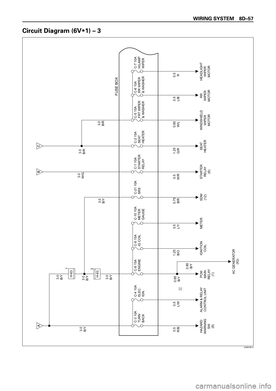
3.0
B/Y3.0
B/Y
3.0
B/Y3.0
B/Y3.0
W/G3.0
B/R
3.0
B/R 3.0
B/Y
0.5
R/B
HAZARD
WARNING
SW
(8)PCM
MAIN
RELAY
(1)IGNITION
COILMETER STARTER
RELAY
(6)SEAT
HEATERWINDSHIELD
WIPER
MOTORRR
WIPER
MOTORHEADLIGHT
WIPER
MOTOR
AC GENERATOR
(IG) ALARM & RELAY
CONTROL UNIT C-3 10A
TURN
BACK
0.5
L/WC-4 10A
ELEC.
IGN.
0.5
L/YC-10 10A
METER
GAUGE
0.5
W/RC-1 10A
STARTER
RELAY
0.85
W/LC-5 15A
FRT WIPER
& WASHERC-6 10A
RR WIPER
& WASHERC-7 10A
H/LAMP
WIPER
FUSE BOX
1.25
B/OC-9 15A
IG COIL C-8 15A
ENGINE
0.5
L/B
0.85
B/Y
0.85
B/Y
0.5
R
0.75
B/R
SDM
(12)C-21 10A
SRS
1.25
G/RC-2 15A
SEAT
HEATER
H-631
3
H-63
��
D08RWB15
Page 2658 of 6000

3.0
B/Y3.0
B/Y
3.0
B/Y3.0
B/Y3.0
W/G3.0
B/R
3.0
B/R 3.0
B/Y
0.5
R/B
HAZARD
WARNING
SW
(8)C-3 10A
TURN
BACK
0.5
L/WC-4 10A
ELEC.
IGN.
0.5
L/Y
METER ECM
(J2-9) ALARM & RELAY��
C O NTR O L UNITC-10 10A
METER
GAUGE
0.5
W/R
STARTER
RELAY
(6)C-1 10A
STARTER
RELAY
0.85
W/L
WINDSHIELD
WIPER
MOTORC-5 15A
FRT WIPER
& WASHERC-6 10A
RR WIPER
& WASHERC-7 10A
H/LAMP
WIPER
FUSE BOX
C-8 15A
ENGINE
0.5
L/B
RR
WIPER
MOTORHEADLIGHT
WIPER
MOTOR
0.85
B/Y
0.5
R
0.75
B/R
SDM
(12)C-21 10A
SRS
1.25
G/R
SEAT
HEATERC-2 15A
SEAT
HEATER
H-631
3
H-63
��
D08RWB20
Page 2682 of 6000

3.0
B/Y
C-3 10A
TURN, BACKC-1 10A
STARTER RELAYSTARTER SW
(IG1)EHCU : ELECTRONIC HYDRAULIC CONTROL UNIT
PCM : POWERTRAIN CONTROL MODULE
P C M
H-11H-7
6M-25
3 0.85
R/B
0.75
R/B
0.75
R/L
BACKUP
LIGHT 0.5
R/B
17M-258H-117
3.0
W/GSTARTER SW
(ST)
H-10H-12
0.5
W/L
1.25
W/L
STARTER
RELAY (6)0.5
W/RM-25
M-25
5C-3
E12 0.5
L/W
0.5
L/WH-531
M-25
6C-3
E7 0.5
L/Y
0.5
L/YH-532
M-25
7C-3
F2 0.5
L/B
0.5
L/BH-533
M-25
2C-3
F3 0.5
Y/G
0.5
Y/GH-534
8
H-87
MODE SW
1 152
C-1EHCU (6)
0.5
GR
A12
C-3
CRUISE CONTROL
UNIT (5)
0.5
GR/L
F10
M-25
1.25
W/RH-104
16H-42
D08RW595
Page 2697 of 6000

3.0
B/Y
C-3 10A
TURN, BACKC-1 10A
STARTER RELAYSTARTER SW
(IG1)EHCU : ELECTRONIC HYDRAULIC CONTROL UNIT
PCM : POWERTRAIN CONTROL MODULE
P C M
H-11H-8
6M-25
3 0.85
R/B
0.75
R/B
0.75
R/L
BACKUP
LIGHT 0.5
R/B
4M-258H-117
3.0
W/GSTARTER SW
(ST)
H-10H-8
0.5
W/L
1.25
W/L
STARTER
RELAY (6)0.5
W/RM-25
M-25
5C-3
E12 0.5
L/W
0.5
L/WH-531
M-25
6C-3
E7 0.5
L/Y
0.5
L/YH-532
M-25
7C-3
F2 0.5
L/B
0.5
L/BH-533
M-25
2C-3
F3 0.5
Y/G
0.5
Y/GH-534
8
H-72
MODE SW
1 151
C-1EHCU (6)
0.5
GR
A12
C-3
CRUISE CONTROL
UNIT (5)
0.5
GR/L
F10
M-25
1.25
W/RH-104
16H-42
D08RW909
Page 2787 of 6000

I-115
B-53
B1
H-2716
H-257
B-53
2 L
H-25100.85
R/B0.85
G/O
H-1612
HAZARD
WARNING
SW
TURN SIGNAL
LIGHT SWFLASHER
UNIT
0.85
G/B0.85
G/B
0.85
G/B0.85
P/B
0.85
P/B2.0
G/O0.3
R/G 0.85
G/R
ILLUMINATION
CONTROLLER
(3) 0.85
P/B 2.0
LG/B 0.5
B
1.25
B2.0
LG/B
2.0
LG/B
2.0
LG/B2.0
B/R2.0
B/R
0.85
R/B 0.85
R/B2.0
G/O
5.0
W BATT.(+)
F-3 15A
HORN,HAZARD3.0
B/Y STARTER SW
(IG1)
C-3 10A
TURN
BACK
B-12
B-12
4
B-12
5 3
LR
A
I-11I-11I-11I-11
64 2 1
I-117I-118I-11 TAIL RELAY
(4) BACK UP
LIGHT
3
B
B-53
3 E
HORN RELAY
(2)
H-276H-2710
B-19
BODY-RH
D08RW683
Page 2791 of 6000

I-115
B-53
B1
H-204
H-202
B-53
2 L
H-25170.85
R/B0.85
G/O
H-1614
HAZARD
WARNING
SW
TURN SIGNAL
LIGHT SWFLASHER
UNIT
0.85
G/B0.85
G/B
0.85
G/B0.85
P/B
0.85
P/B2.0
G/O0.3
R/G 0.85
G/R
ILLUMINATION
CONTROLLER
(3) 0.85
P/B 2.0
LG/B 0.5
B
1.25
B2.0
LG/B
2.0
LG/B
2.0
LG/B2.0
B/R2.0
B/R
0.85
R/B 0.85
R/B2.0
G/O
5.0
W BATT.(+)
F-3 15A
HORN,HAZARD3.0
B/Y STARTER SW
(IG1)
C-3 10A
TURN
BACK
B-12
B-12
4
B-12
5 3
LR
A
I-11I-11I-11I-11
64 2 1
I-117I-118I-11 TAIL RELAY
(4) BACK UP
LIGHT
3
B
B-53
3 E
HORN RELAY
(2)
H-2519H-2520
B-19
BODY-LH
D08RW872
Page 2814 of 6000

3.0
B/Y STARTER SW
(IG1)
MODE
SW
(A/T)
HAZARD
WARN ING
SWITCH (8)0.5
R/B
0.5
R/B 0.5
R/B
0.85
R/B
0.5
R/L0.75
R/L 0.75
R/LC-3 10A
TURN,BACK
H-2517H-717
M-25
M-258
H-117
R-4 3
A
BACKUP
LIGHT SW
(6VD1 M/T)
BACKUP
LIGHT
-LHBACKUP
LIGHT
-RH
0.85
R/B
0.75
R/B
0.5
R/L
H-11
1 6
M-8
M-91
0.85
R/L
H-55
BACKUP
LIGHT SW
(4JG2)
0.5
R/B
0.85
R/B
0.5
R/L
H-5
E-43
1 6
E-421
0.5
R/L
0.85
R/L
0.5
R/L
1.25
B1.25
B 0.5
R/L
H-328
H-716
A
BODY-RR
R-133
R-13
1
R-123
1
R-12 0.75
R/B
H-116
H-117
D08RWC64