Back OPEL FRONTERA 1998 Workshop Manual
[x] Cancel search | Manufacturer: OPEL, Model Year: 1998, Model line: FRONTERA, Model: OPEL FRONTERA 1998Pages: 6000, PDF Size: 97 MB
Page 2334 of 6000

7B–16MANUAL TRANSMISSION
19. Connect the backup lamp switch, 4WD indicator
switch, and 1-2 indicator switch harness connectors.
826RW023
20. Install the front and 3 way exhaust pipe (6VE1).
Install the exhaust pipe with catalytic converter
(4JX1).
Torque:
Exhaust pipe to exhaust manifold:
67 Nꞏm (6.8 kgꞏm/49 Ib ft)
Exhaust pipe flange bolt:
43 Nꞏm (4.4 kgꞏm/32 Ib ft)
(4JX1)
150RW041
21. Connect two oxygen sensor connectors to the
transmission harness (6VE1).
22. Install the front propeller shaft and tighten the fixing
bolts and nuts specified torque.
Torque: 63 Nꞏm (6.4 kgꞏm/46 Ib ft)
23. Install the rear propeller shaft and tighten the fixing
bolts and nuts specified torque.
Torque: 63 Nꞏm (6.4 kgꞏm/46 Ib ft)24. Install transfer protector and tighten the fixing bolts
specified torque.
Torque: 37 Nꞏm (3.8 kgꞏm/27 Ib ft)
25. Install the transmission control lever and transfer
control lever.
235RW014
26. Install the grommet assembly.
27. Install the front console assembly.
28. Install the gear control lever knob.
29. Connect battery ground cable.
30. Install engine hood.
Page 2338 of 6000

7B–20MANUAL TRANSMISSION
220RW095
Legend
(1) Release Bearing and Shift Fork
(2) Clutch Housing
(3) Front Cover
(4) Snap Ring
(5) Snap Ring
(6) 1st and 2nd Switch
(7) Drain Plug
(8) Backup Light Switch
(9) Transmission Case(10) Filler Plug
(11) Gear Control Rod
(12) Reverse Restrict Pin
(13) Oil Receiver Pipe
(14) Transfer Adapter
(15) Plug (6VE1) or Neutral Switch (4JX1)
(16) Gear Control Box
(17) Shift Lever Housing
(18) Oil Seal
(19) Plug
Page 2339 of 6000

MANUAL TRANSMISSION7B–21
Disassembly
1. Remove the drain plug and filler plug.
1. Remove the drain plug (1) and gasket.
2. Remove the filler plug (2) and gasket.
(6VE1)
220RW007
2. Remove the clutch release bearing and shift fork.
1. Remove the clutch release bearing (3) from the
front cover.
2. Remove the split pin (4). Remove the shaft from
the under. Remove the shift fork (5).
220RW086
3. Remove the switch.
1. Remove backup light switch (6) and gasket.
2. Remove neutral switch (7) and gasket (4JX1).
3. Remove 1st and 2nd switch (8) and gasket.
(4JX1)
220RW093
4. Remove the clutch housing.
1. Remove the 9 bolts.
241RW001
Page 2360 of 6000

7B–42MANUAL TRANSMISSION
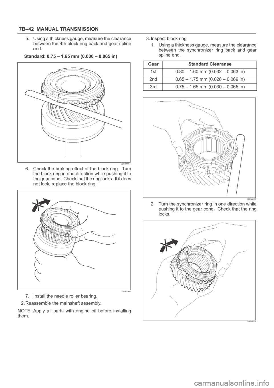
5. Using a thickness gauge, measure the clearance
between the 4th block ring back and gear spline
end.
Standard: 0.75 – 1.65 mm (0.030 – 0.065 in)
226RW064
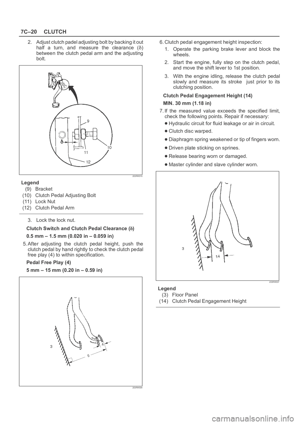
6. Check the braking effect of the block ring. Turn
the block ring in one direction while pushing it to
the gear cone. Check that the ring locks. If it does
not lock, replace the block ring.
226RW060
7. Install the needle roller bearing.
2. Reassemble the mainshaft assembly.
NOTE: Apply all parts with engine oil before installing
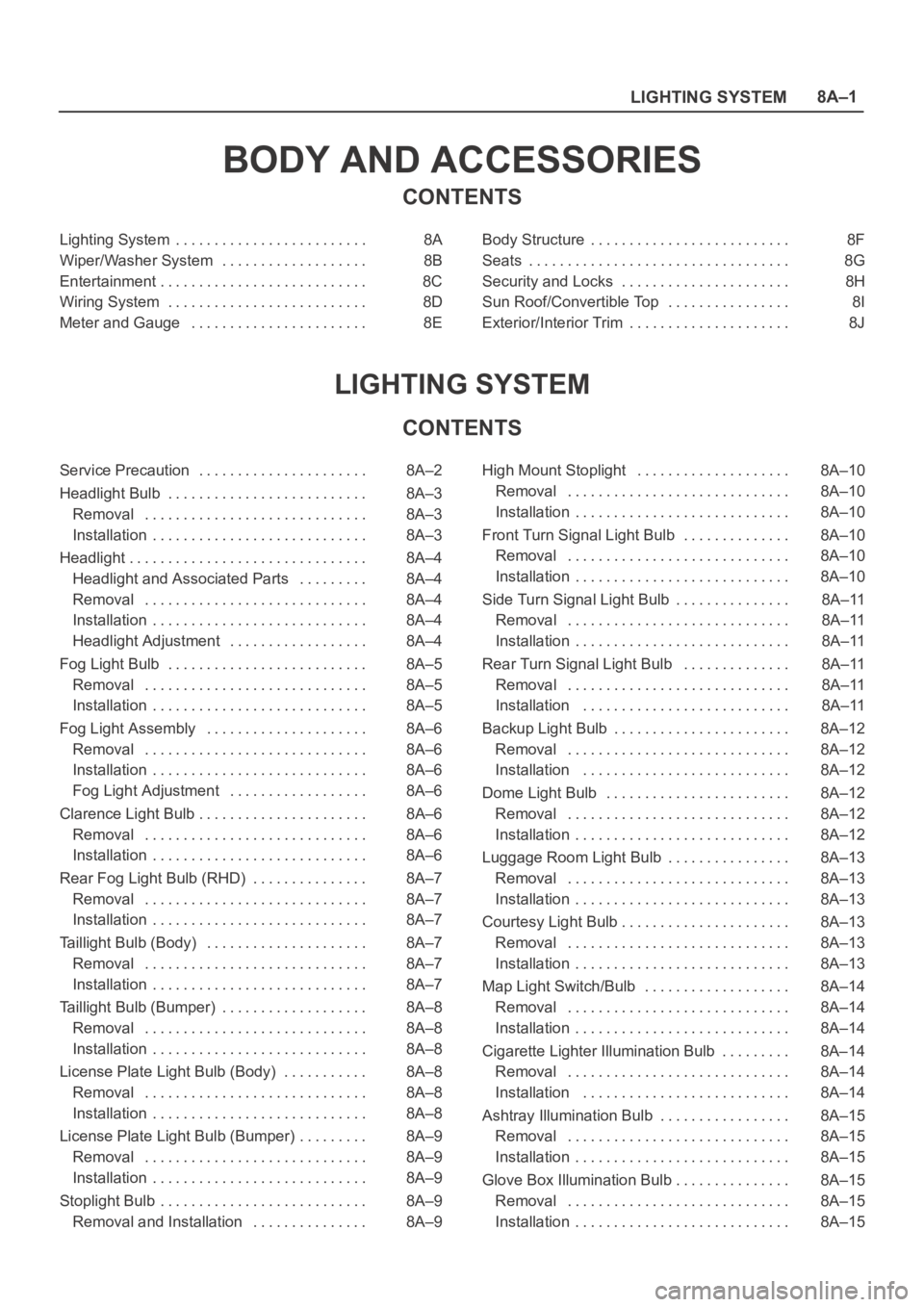
them.3. Inspect block ring
1. Using a thickness gauge, measure the clearance
between the synchronizer ring back and gear
spline end.
Gear
Standard Clearanse
1st0.80–1.60mm (0.032–0.063in)
2nd0.65–1.75mm (0.026–0.069in)
3rd0.75–1.65mm (0.030–0.065in)
226RW105
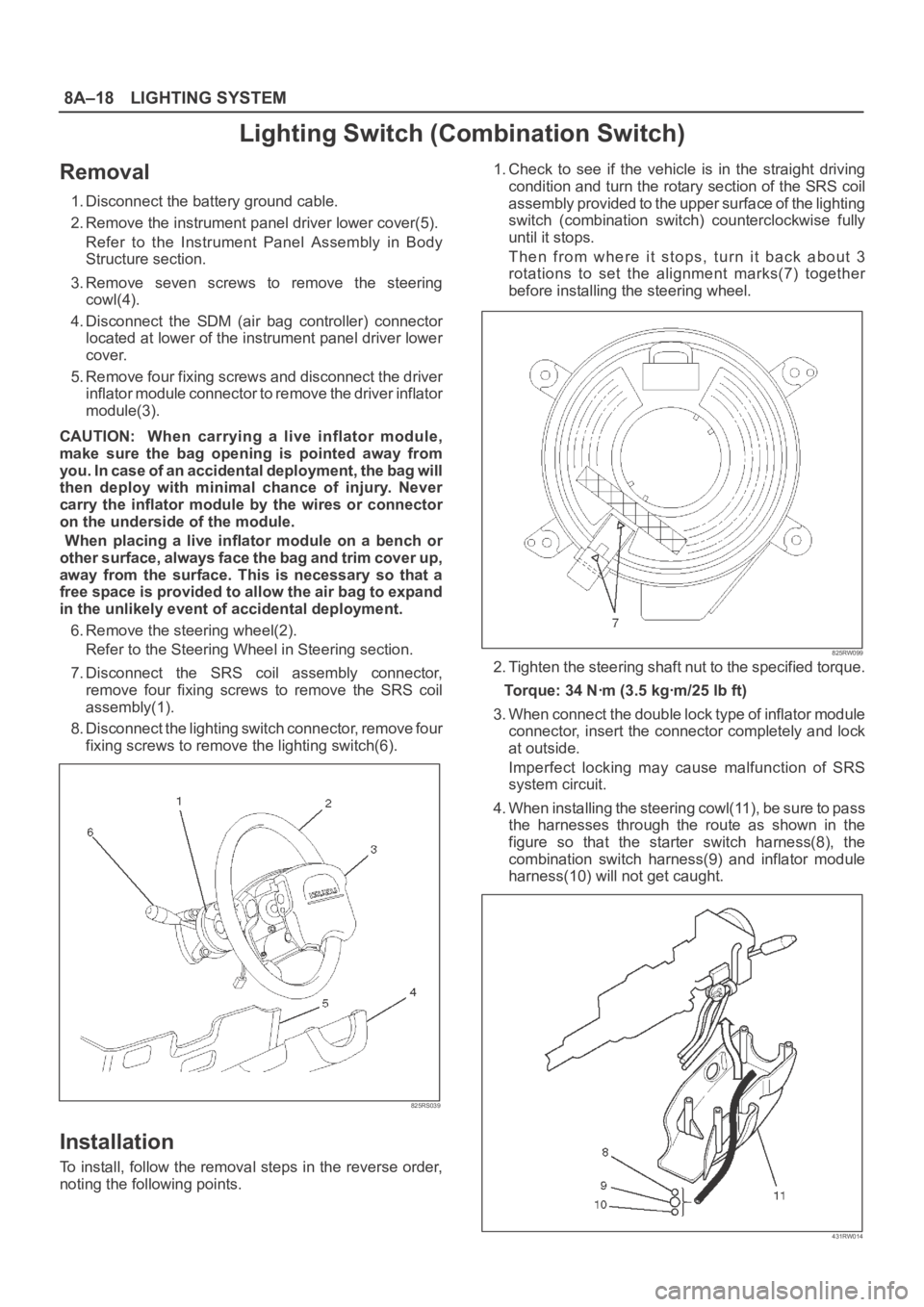
2. Turn the synchronizer ring in one direction while
pushing it to the gear cone. Check that the ring
locks.
226RW106
Page 2384 of 6000

7B–66MANUAL TRANSMISSION
38. Install clutch housing.
1. Install the clutch housing to the transmission
case.
Torque: 36 Nꞏm (3.7 kgꞏm/27 lb ft)
NOTE: Tighten the all bolts evenly.
241RW001
39. Install the switches.
1. Install the new gasket to the 1st and 2nd switch.
2. Install the 1st and 2nd switch assembly (8).
Torque: 39 Nꞏm (4.0 kgꞏm/29 lb ft)
3. Install the new gasket to the backup light switch.
4. Install the backup light switch assembly (6).
Torque: 44 Nꞏm (4.5 kgꞏm/33 lb ft)
5. Install the new gasket to the neutral switch.
6. Install the neutral switch (7) to the transfer
adapter (4JX1).
Torque: 37 Nꞏm (3.8 kgꞏm/27 lb ft)
(4JX1)
220RW093
40. Install the clutch release bearing (3) and clutch shift
fork (5).
1. Apply the clutch release grease.
1. Fitting surface of the cylinder push rod.
2. Fitting surface of the release bearing hub.
3. The hole of the fork split pin (4).
2. Apply the clutch release grease.
1. The spline surface of the top gear shaft.
3. Install the clutch shift fork (5).
4. Install the snap pin.
5. Install the clutch release bearing (3) to the clutch
shift fork (5).
220RW086
Page 2529 of 6000

7C–20CLUTCH
2. Adjust clutch padel adjusting bolt by backing it out
half a turn, and measure the clearance (
)
between the clutch pedal arm and the adjusting
bolt.
203RW010
Legend
(9) Bracket
(10) Clutch Pedal Adjusting Bolt
(11) Lock Nut
(12) Clutch Pedal Arm
3. Lock the lock nut.
Clutch Switch and Clutch Pedal Clearance (
)
0.5 mm – 1.5 mm (0.020 in – 0.059 in)
5. After adjusting the clutch pedal height, push the
clutch pedal by hand rightly to check the clutch pedal
free play (4) to within specification.
Pedal Free Play (4)
5 mm – 15 mm (0.20 in – 0.59 in)
203RW004
6. Clutch pedal engagement height inspection:
1. Operate the parking brake lever and block the
wheels.
2. Start the engine, fully step on the clutch pedal,
and move the shift lever to 1st position.
3. With the engine idling, release the clutch pedal
slowly and measure its stroke just prior to its
clutching position.
Clutch Pedal Engagement Height (14)
MIN. 30 mm (1.18 in)
7. If the measured value exceeds the specified limit,
check the following points. Repair if necessary:
Hydraulic circuit for fluid leakage or air in circuit.
Clutch disc warped.
Diaphragm spring weakened or tip of fingers worn.
Driven plate sticking on sprines.
Release bearing worn or damaged.
Master cylinder and slave cylinder worn.
203RW007
Legend
(3) Floor Panel
(14) Clutch Pedal Engagement Height
Page 2540 of 6000

LIGHTING SYSTEM8A–1
BODY AND ACCESSORIES
CONTENTS
Lighting System 8A. . . . . . . . . . . . . . . . . . . . . . . . .
Wiper/Washer System 8B. . . . . . . . . . . . . . . . . . .
Entertainment 8C. . . . . . . . . . . . . . . . . . . . . . . . . . .
Wiring System 8D. . . . . . . . . . . . . . . . . . . . . . . . . .
Meter and Gauge 8E. . . . . . . . . . . . . . . . . . . . . . . Body Structure 8F. . . . . . . . . . . . . . . . . . . . . . . . . .
Seats 8G. . . . . . . . . . . . . . . . . . . . . . . . . . . . . . . . . .
Security and Locks 8H. . . . . . . . . . . . . . . . . . . . . .
Sun Roof/Convertible Top 8I. . . . . . . . . . . . . . . .
Exterior/Interior Trim 8J. . . . . . . . . . . . . . . . . . . . .
LIGHTING SYSTEM
CONTENTS
Service Precaution 8A–2. . . . . . . . . . . . . . . . . . . . . .
Headlight Bulb 8A–3. . . . . . . . . . . . . . . . . . . . . . . . . .
Removal 8A–3. . . . . . . . . . . . . . . . . . . . . . . . . . . . .
Installation 8A–3. . . . . . . . . . . . . . . . . . . . . . . . . . . .
Headlight 8A–4. . . . . . . . . . . . . . . . . . . . . . . . . . . . . . .
Headlight and Associated Parts 8A–4. . . . . . . . .
Removal 8A–4. . . . . . . . . . . . . . . . . . . . . . . . . . . . .
Installation 8A–4. . . . . . . . . . . . . . . . . . . . . . . . . . . .
Headlight Adjustment 8A–4. . . . . . . . . . . . . . . . . .
Fog Light Bulb 8A–5. . . . . . . . . . . . . . . . . . . . . . . . . .
Removal 8A–5. . . . . . . . . . . . . . . . . . . . . . . . . . . . .
Installation 8A–5. . . . . . . . . . . . . . . . . . . . . . . . . . . .
Fog Light Assembly 8A–6. . . . . . . . . . . . . . . . . . . . .
Removal 8A–6. . . . . . . . . . . . . . . . . . . . . . . . . . . . .
Installation 8A–6. . . . . . . . . . . . . . . . . . . . . . . . . . . .
Fog Light Adjustment 8A–6. . . . . . . . . . . . . . . . . .
Clarence Light Bulb 8A–6. . . . . . . . . . . . . . . . . . . . . .
Removal 8A–6. . . . . . . . . . . . . . . . . . . . . . . . . . . . .
Installation 8A–6. . . . . . . . . . . . . . . . . . . . . . . . . . . .
Rear Fog Light Bulb (RHD) 8A–7. . . . . . . . . . . . . . .
Removal 8A–7. . . . . . . . . . . . . . . . . . . . . . . . . . . . .
Installation 8A–7. . . . . . . . . . . . . . . . . . . . . . . . . . . .
Taillight Bulb (Body) 8A–7. . . . . . . . . . . . . . . . . . . . .
Removal 8A–7. . . . . . . . . . . . . . . . . . . . . . . . . . . . .
Installation 8A–7. . . . . . . . . . . . . . . . . . . . . . . . . . . .
Taillight Bulb (Bumper) 8A–8. . . . . . . . . . . . . . . . . . .
Removal 8A–8. . . . . . . . . . . . . . . . . . . . . . . . . . . . .
Installation 8A–8. . . . . . . . . . . . . . . . . . . . . . . . . . . .
License Plate Light Bulb (Body) 8A–8. . . . . . . . . . .
Removal 8A–8. . . . . . . . . . . . . . . . . . . . . . . . . . . . .
Installation 8A–8. . . . . . . . . . . . . . . . . . . . . . . . . . . .
License Plate Light Bulb (Bumper) 8A–9. . . . . . . . .
Removal 8A–9. . . . . . . . . . . . . . . . . . . . . . . . . . . . .
Installation 8A–9. . . . . . . . . . . . . . . . . . . . . . . . . . . .
Stoplight Bulb 8A–9. . . . . . . . . . . . . . . . . . . . . . . . . . .
Removal and Installation 8A–9. . . . . . . . . . . . . . . High Mount Stoplight 8A–10. . . . . . . . . . . . . . . . . . . .
Removal 8A–10. . . . . . . . . . . . . . . . . . . . . . . . . . . . .
Installation 8A–10. . . . . . . . . . . . . . . . . . . . . . . . . . . .
Front Turn Signal Light Bulb 8A–10. . . . . . . . . . . . . .
Removal 8A–10. . . . . . . . . . . . . . . . . . . . . . . . . . . . .
Installation 8A–10. . . . . . . . . . . . . . . . . . . . . . . . . . . .
Side Turn Signal Light Bulb 8A–11. . . . . . . . . . . . . . .
Removal 8A–11. . . . . . . . . . . . . . . . . . . . . . . . . . . . .
Installation 8A–11. . . . . . . . . . . . . . . . . . . . . . . . . . . .
Rear Turn Signal Light Bulb 8A–11. . . . . . . . . . . . . .
Removal 8A–11. . . . . . . . . . . . . . . . . . . . . . . . . . . . .
Installation 8A–11. . . . . . . . . . . . . . . . . . . . . . . . . . .
Backup Light Bulb 8A–12. . . . . . . . . . . . . . . . . . . . . . .
Removal 8A–12. . . . . . . . . . . . . . . . . . . . . . . . . . . . .
Installation 8A–12
. . . . . . . . . . . . . . . . . . . . . . . . . . .
Dome Light Bulb 8A–12. . . . . . . . . . . . . . . . . . . . . . . .
Removal 8A–12. . . . . . . . . . . . . . . . . . . . . . . . . . . . .
Installation 8A–12. . . . . . . . . . . . . . . . . . . . . . . . . . . .
Luggage Room Light Bulb 8A–13. . . . . . . . . . . . . . . .
Removal 8A–13. . . . . . . . . . . . . . . . . . . . . . . . . . . . .
Installation 8A–13. . . . . . . . . . . . . . . . . . . . . . . . . . . .
Courtesy Light Bulb 8A–13. . . . . . . . . . . . . . . . . . . . . .
Removal 8A–13. . . . . . . . . . . . . . . . . . . . . . . . . . . . .
Installation 8A–13. . . . . . . . . . . . . . . . . . . . . . . . . . . .
Map Light Switch/Bulb 8A–14. . . . . . . . . . . . . . . . . . .
Removal 8A–14. . . . . . . . . . . . . . . . . . . . . . . . . . . . .
Installation 8A–14. . . . . . . . . . . . . . . . . . . . . . . . . . . .
Cigarette Lighter Illumination Bulb 8A–14. . . . . . . . .
Removal 8A–14. . . . . . . . . . . . . . . . . . . . . . . . . . . . .
Installation 8A–14. . . . . . . . . . . . . . . . . . . . . . . . . . .
Ashtray Illumination Bulb 8A–15. . . . . . . . . . . . . . . . .
Removal 8A–15. . . . . . . . . . . . . . . . . . . . . . . . . . . . .
Installation 8A–15. . . . . . . . . . . . . . . . . . . . . . . . . . . .
Glove Box Illumination Bulb 8A–15. . . . . . . . . . . . . . .
Removal 8A–15. . . . . . . . . . . . . . . . . . . . . . . . . . . . .
Installation 8A–15. . . . . . . . . . . . . . . . . . . . . . . . . . . .
Page 2551 of 6000

8A–12LIGHTING SYSTEM
Backup Light Bulb
Removal
1. Disconnect the battery ground cable.
2. Remove three screws and release the lock at two
positions.
3. Remove the rear combination light(3).
4. Remove the backup light socket/bulb(1) by turning it
counterclockwise.
5. Remove the bulb(2) by turning it counterclockwise
while pushing it at the same time.
803RS001
Installation
To install, follow the removal steps in the reverse order.
Dome Light Bulb
Removal
1. Disconnect the battery ground cable.
2. Remove the lens(2) by releasing the locks at three
locations.
3. Remove the bulb(1).
805RS005
Installation
To install, follow the removal steps in the reverse order.
Page 2557 of 6000

8A–18LIGHTING SYSTEM
Lighting Switch (Combination Switch)
Removal
1. Disconnect the battery ground cable.
2. Remove the instrument panel driver lower cover(5).
Refer to the Instrument Panel Assembly in Body
Structure section.
3. Remove seven screws to remove the steering
cowl(4).
4. Disconnect the SDM (air bag controller) connector
located at lower of the instrument panel driver lower
cover.
5. Remove four fixing screws and disconnect the driver
inflator module connector to remove the driver inflator
module(3).
CAUTION: When carrying a live inflator module,
make sure the bag opening is pointed away from
y o u . I n c a s e o f a n a c c i d e n t a l d e p l o y m e n t , t h e b a g w i l l
then deploy with minimal chance of injury. Never
carry the inflator module by the wires or connector
on the underside of the module.
When placing a live inflator module on a bench or
other surface, always face the bag and trim cover up,
away from the surface. This is necessary so that a
free space is provided to allow the air bag to expand
in the unlikely event of accidental deployment.
6. Remove the steering wheel(2).
Refer to the Steering Wheel in Steering section.
7. Disconnect the SRS coil assembly connector,
remove four fixing screws to remove the SRS coil
assembly(1).
8. Disconnect the lighting switch connector, remove four
fixing screws to remove the lighting switch(6).
825RS039
Installation
To install, follow the removal steps in the reverse order,
noting the following points.1. Check to see if the vehicle is in the straight driving
condition and turn the rotary section of the SRS coil
assembly provided to the upper surface of the lighting
switch (combination switch) counterclockwise fully
until it stops.
Then from where it stops, turn it back about 3
rotations to set the alignment marks(7) together
before installing the steering wheel.
825RW099
2. Tighten the steering shaft nut to the specified torque.
Torque: 34 Nꞏm (3.5 kgꞏm/25 lb ft)
3. When connect the double lock type of inflator module
connector, insert the connector completely and lock
at outside.
Imperfect locking may cause malfunction of SRS
system circuit.
4. When installing the steering cowl(11), be sure to pass
the harnesses through the route as shown in the
figure so that the starter switch harness(8), the
combination switch harness(9) and inflator module
harness(10) will not get caught.
431RW014
Page 2558 of 6000

LIGHTING SYSTEM8A–19
Fog Light Switch
Removal
1. Disconnect the battery ground cable.
2. Remove the front console assembly(1).
Refer to the Instrument Panel Assembly in Body
Structure section.
3. Remove the lower cluster assembly(2).
Refer to the Instrument Panel Assembly in Body
Structure section.
4. Remove the instrument panel driver lower cover
assembly(3).
Refer to the Instrument Panel Assembly in Body
Structure section.
821RW024
5. Remove the instrument panel cluster assembly(4).
Refer to the Instrument Panel Assembly in Body
Structure section.
6. Disconnect the connector and push the lock from the
back side of the instrument panel cluster assembly to
remove the fog light switch(5).
825RW027
Installation
To install, follow the removal steps in the reverse order,
noting the following point:
1. Push in the switch with your fingers until the switch is
locked securely.