battery OPEL FRONTERA 1998 Owner's Manual
[x] Cancel search | Manufacturer: OPEL, Model Year: 1998, Model line: FRONTERA, Model: OPEL FRONTERA 1998Pages: 6000, PDF Size: 97 MB
Page 643 of 6000

DRIVE LINE CONTROL SYSTEM (TOD) 4B2–72
StepActionYe sNo
1Turn on the starter switch.
When the transfer lever is shifted to the high position, is 5V
observed between terminals 9 and 19 (4L switch)?
Go to Step 2Go to Step 4
2When the transfer lever is shifted to the neutral position, is 0V
observed between terminals 9 and 19 (4L switch)?
Go to Step 3Go to Step 4
3When the transfer lever is shifted to the 4L position, is 0V
observed between terminals 9 and 19 (4L switch)?The ECU has
failed. Replace
the ECU.
Go to Step 4
Go to Step 4
41. Turn off the starter switch.
2. Disconnect the ECU connector.
3. Turn on the starter switch.
When the transfer lever is shifted to the high position, is 12V
observed between terminals (B–68)4 and (B–67)11?
Go to Step 5Go to Step 7
5When the transfer lever is shifted to the neutral position, is 0V
observed between terminals (B–68)4 and (B–67)11?
Go to Step 6Go to Step 7
6When the transfer lever is shifted to the 4L position, is 0V
observed between terminals (B–68)4 and (B–67)11?The 4L switch
circuit battery is
short-circuited
between ECU
and transfer.
Repair the circuit
Go to Step 13
Go to Step 7
7Turn off the starter switch.
When the transfer lever is shifted to the high position, is the
continuity established between terminals (B–68)3 and (B–67)11?
Go to Step 10Go to Step 8
8When the transfer lever is shifted to the neutral position between
high and 4L, is the continuity established between terminals
(B–68)4 and (B–67)11?
Go to Step 9Go to Step 10
9When the transfer lever is shifted to the 4L position, is the
continuity established between terminals (B–68)4 and (B–67)11?The phenomenon
is not
reproduced.
Refer to
“Troubles
intermittently
observed”.
Go to Step 13
Go to Step 10
101. Disconnect the A–3 connector.
When the transfer lever is shifted to the neutral position between
high and 4L, is the continuity established between transfer
connector terminals (A–3)12 and GND?Wires are broken
between transfer
connector (A–3)
and floor
connector (H-49).
Repair the circuit.
Go to Step 11
Repair the
transfer
assembly.
Go to Step 13
11When the transfer lever is shifted to the 4L position, is the
continuity established between transfer connector terminals
(A–3)12 and GND?
Go to Step 12
Repair the
transfer
assembly.
Go to Step 13
12When the transfer lever is shifted to the high position, is the
continuity established between transfer connector terminals
(A–3)12 and GND?Repair the
transfer
assembly.
Go to Step 13
Go to Step 13
13Check that all the parts are mounted.
Is this step complete?Repeat the
“Diagnosis Flow”.
Return to Step 13
Page 648 of 6000
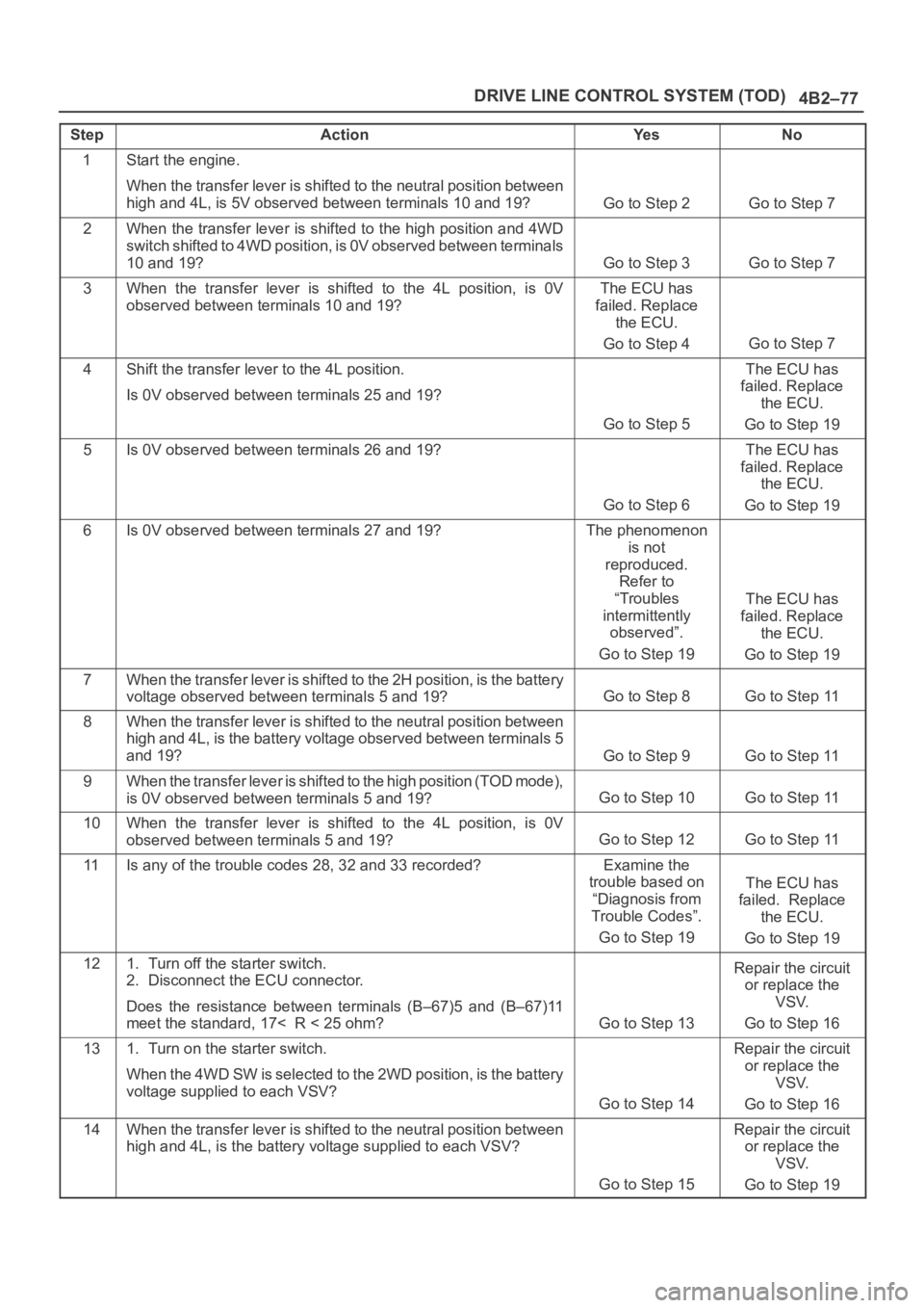
4B2–77 DRIVE LINE CONTROL SYSTEM (TOD)
StepActionYe sNo
1Start the engine.
When the transfer lever is shifted to the neutral position between
high and 4L, is 5V observed between terminals 10 and 19?
Go to Step 2Go to Step 7
2When the transfer lever is shifted to the high position and 4WD
switch shifted to 4WD position, is 0V observed between terminals
10 and 19?
Go to Step 3Go to Step 7
3When the transfer lever is shifted to the 4L position, is 0V
observed between terminals 10 and 19?The ECU has
failed. Replace
the ECU.
Go to Step 4
Go to Step 7
4Shift the transfer lever to the 4L position.
Is 0V observed between terminals 25 and 19?
Go to Step 5
The ECU has
failed. Replace
the ECU.
Go to Step 19
5Is 0V observed between terminals 26 and 19?
Go to Step 6
The ECU has
failed. Replace
the ECU.
Go to Step 19
6Is 0V observed between terminals 27 and 19?The phenomenon
is not
reproduced.
Refer to
“Troubles
intermittently
observed”.
Go to Step 19
The ECU has
failed. Replace
the ECU.
Go to Step 19
7When the transfer lever is shifted to the 2H position, is the battery
voltage observed between terminals 5 and 19?
Go to Step 8Go to Step 11
8When the transfer lever is shifted to the neutral position between
high and 4L, is the battery voltage observed between terminals 5
and 19?
Go to Step 9Go to Step 11
9When the transfer lever is shifted to the high position (TOD mode),
is 0V observed between terminals 5 and 19?
Go to Step 10Go to Step 11
10When the transfer lever is shifted to the 4L position, is 0V
observed between terminals 5 and 19?
Go to Step 12Go to Step 11
11Is any of the trouble codes 28, 32 and 33 recorded?Examine the
trouble based on
“Diagnosis from
Trouble Codes”.
Go to Step 19
The ECU has
failed. Replace
the ECU.
Go to Step 19
121. Turn off the starter switch.
2. Disconnect the ECU connector.
Does the resistance between terminals (B–67)5 and (B–67)11
meet the standard, 17< R < 25 ohm?
Go to Step 13
Repair the circuit
or replace the
VSV.
Go to Step 16
131. Turn on the starter switch.
When the 4WD SW is selected to the 2WD position, is the battery
voltage supplied to each VSV?
Go to Step 14
Repair the circuit
or replace the
VSV.
Go to Step 16
14When the transfer lever is shifted to the neutral position between
high and 4L, is the battery voltage supplied to each VSV?
Go to Step 15
Repair the circuit
or replace the
VSV.
Go to Step 19
Page 651 of 6000

DRIVE LINE CONTROL SYSTEM (TOD) 4B2–80
StepActionYe sNo
1Start the engine.
When the transfer lever is shifted to the neutral position between
high and 4L, is 5V observed between terminals 10 and 19?
Go to Step 2Go to Step 7
2When the transfer lever is shifted to the high position and 4WD
switch shifted to 4WD position, is 0V observed between terminals
10 and 19?
Go to Step 3Go to Step 7
3When the transfer lever is shifted to the 4L position, is 0V
observed between terminals 10 and 19?
Go to Step 4Go to Step 7
4Select the 4WD SW to the 2WD position.
Is 12V observed between terminals 25 and 19?
Go to Step 5Go to Step 19
5Is 12V observed between terminals 26 and 19?Go to Step 6Go to Step 19
6Is 12V observed between terminals 27 and 19?The phenomenon
is not
reproduced.
Refer to
“Troubles
intermittently
observed”.
Go to Step 19
The ECU has
failed. Replace
the ECU.
Go to Step 19
7When the 4WD SW is select to the 2WD position, is the battery
voltage observed between terminals 5 and 19?
Go to Step 8Go to Step 11
8When the transfer lever is shifted to the neutral position between
high and 4L, is the battery voltage observed between terminals 5
and 19?
Go to Step 9Go to Step 11
9When the transfer lever is shifted to the high position and 4WD
switch shifted to 4WD position, is 0V observed between terminals
5 and 19?
Go to Step 10Go to Step 11
10When the transfer lever is shifted to the 4L position, is 0V
observed between terminals 5 and 19?
Go to Step 12Go to Step 11
11Is any of the trouble codes 28, 32 and 33 recorded?Examine the
trouble based on
“Diagnosis from
Trouble Codes”.
Go to Step 19
The ECU has
failed. Replace
the ECU.
Go to Step 19
121. Turn off the starter switch.
2. Disconnect the ECU connector.
Does the resistance between terminals (B–67)5 and (B–67)11
meet the standard, 17< R < 25 ohm?
Go to Step 13
Repair the circuit
or replace the
VSV.
Go to Step 19
131. Connect the ECU connector.
2. Turn on the starter switch.
When the 4WD SW is select to the 2WD position, is the battery
voltage supplied to each VSV?
Go to Step 14
Repair the circuit
or replace the
VSV.
Go to Step 19
14When the transfer lever is shifted to the neutral position between
high and 4L, is the battery voltage supplied to each VSV?
Go to Step 15
Repair the circuit
or replace the
VSV.
Go to Step 19
15When the transfer lever is shifted to the high position and 4WD
switch shifted to 4WD position, is 0V observed on each VSV?
Go to Step 16
Repair the circuit
or replace the
VSV.
Go to Step 19
Page 656 of 6000

4B2–85 DRIVE LINE CONTROL SYSTEM (TOD)
StepActionYe sNo
11. Disconnect ECU terminal.
2. Turn on the starter switch.
Is battery voltage observed between ECU terminals (B–68)1 and
(B–67)11?
Go to Step 2
Wirers are broken
lighting SW
circuit. Repair
the circuit.
Go to Step 4
2Turn lighting SW “ON”.
Is 0 V observed between ECU terminal (B–68)1 and (B–67)11?
Go to Step 3
Lighting SW
circuit battery
short. Repair the
circuit.
Go to Step 4
3Connect ECU terminal.
While the lighting switch is pressed on and off, does the
brightness of the indicator change?The phenomenon
is not
reproduced.
Refer to
“Troubles
intermittently
observed”
Go to Step 4
The ECU has
failed. Replace
the ECU.
Go to Step 4
4Check that all the parts are mounted.
Is this step complete?Repeat the
“Diagnosis Flow”.
Return to Step 4
Page 659 of 6000
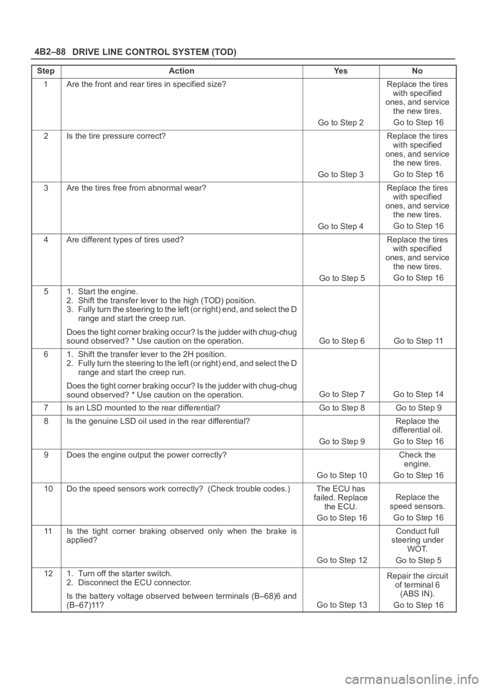
DRIVE LINE CONTROL SYSTEM (TOD) 4B2–88
StepActionYe sNo
1Are the front and rear tires in specified size?
Go to Step 2
Replace the tires
with specified
ones, and service
the new tires.
Go to Step 16
2Is the tire pressure correct?
Go to Step 3
Replace the tires
with specified
ones, and service
the new tires.
Go to Step 16
3Are the tires free from abnormal wear?
Go to Step 4
Replace the tires
with specified
ones, and service
the new tires.
Go to Step 16
4Are different types of tires used?
Go to Step 5
Replace the tires
with specified
ones, and service
the new tires.
Go to Step 16
51. Start the engine.
2. Shift the transfer lever to the high (TOD) position.
3. Fully turn the steering to the left (or right) end, and select the D
range and start the creep run.
Does the tight corner braking occur? Is the judder with chug-chug
sound observed? * Use caution on the operation.
Go to Step 6 Go to Step 11
61. Shift the transfer lever to the 2H position.
2. Fully turn the steering to the left (or right) end, and select the D
range and start the creep run.
Does the tight corner braking occur? Is the judder with chug-chug
sound observed? * Use caution on the operation.
Go to Step 7 Go to Step 14
7Is an LSD mounted to the rear differential? Go to Step 8 Go to Step 9
8Is the genuine LSD oil used in the rear differential?
Go to Step 9
Replace the
differential oil.
Go to Step 16
9Does the engine output the power correctly?
Go to Step 10
Check the
engine.
Go to Step 16
10Do the speed sensors work correctly? (Check trouble codes.)The ECU has
failed. Replace
the ECU.
Go to Step 16
Replace the
speed sensors.
Go to Step 16
11Is the tight corner braking observed only when the brake is
applied?
Go to Step 12
Conduct full
steering under
WOT.
Go to Step 5
121. Turn off the starter switch.
2. Disconnect the ECU connector.
Is the battery voltage observed between terminals (B–68)6 and
(B–67)11?
Go to Step 13
Repair the circuit
of terminal 6
(ABS IN).
Go to Step 16
Page 664 of 6000
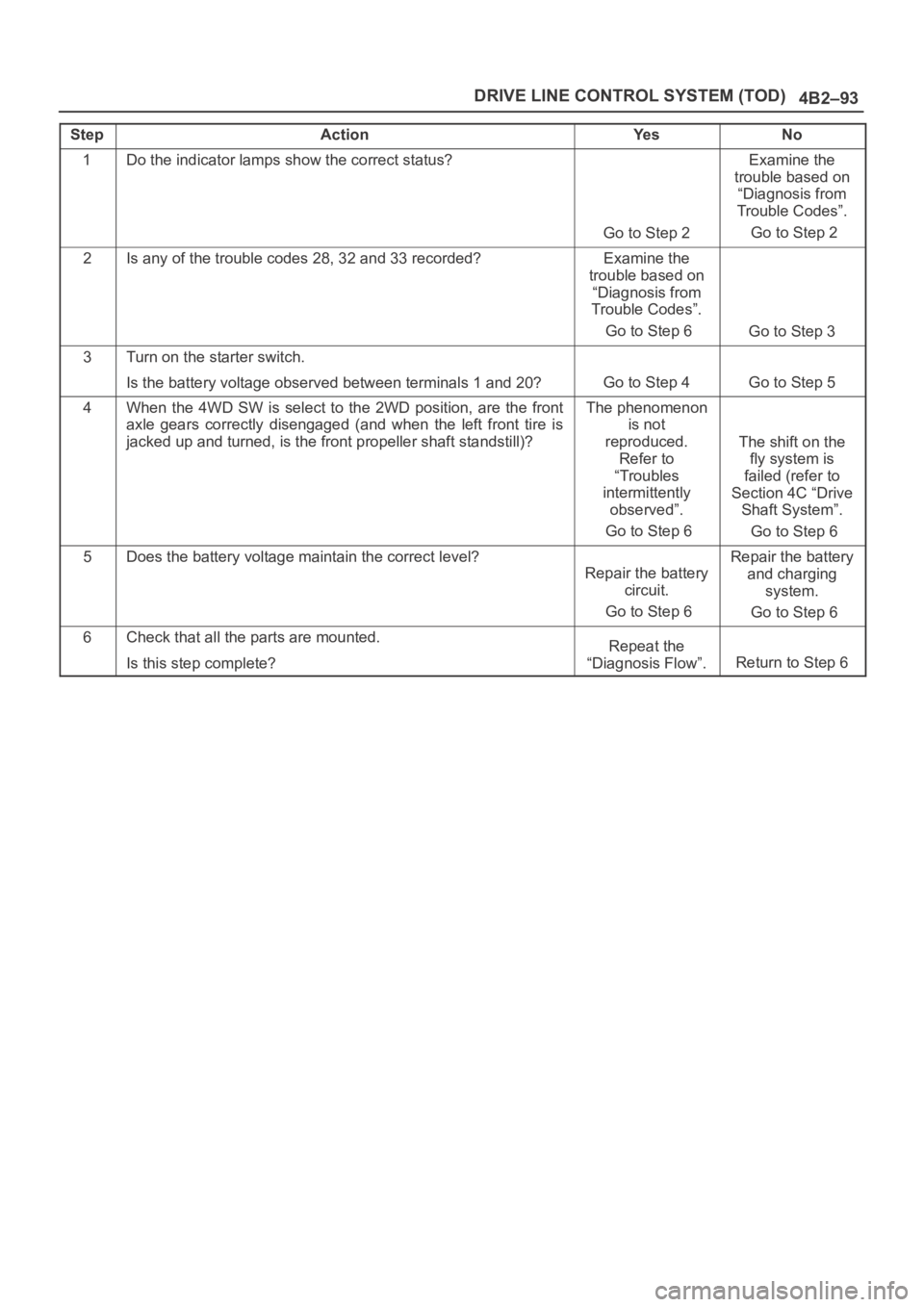
4B2–93 DRIVE LINE CONTROL SYSTEM (TOD)
StepActionYe sNo
1Do the indicator lamps show the correct status?
Go to Step 2
Examine the
trouble based on
“Diagnosis from
Trouble Codes”.
Go to Step 2
2Is any of the trouble codes 28, 32 and 33 recorded?Examine the
trouble based on
“Diagnosis from
Trouble Codes”.
Go to Step 6
Go to Step 3
3Turn on the starter switch.
Is the battery voltage observed between terminals 1 and 20?
Go to Step 4Go to Step 5
4When the 4WD SW is select to the 2WD position, are the front
axle gears correctly disengaged (and when the left front tire is
jacked up and turned, is the front propeller shaft standstill)?The phenomenon
is not
reproduced.
Refer to
“Troubles
intermittently
observed”.
Go to Step 6
The shift on the
fly system is
failed (refer to
Section 4C “Drive
Shaft System”.
Go to Step 6
5Does the battery voltage maintain the correct level?
Repair the battery
circuit.
Go to Step 6
Repair the battery
and charging
system.
Go to Step 6
6Check that all the parts are mounted.
Is this step complete?Repeat the
“Diagnosis Flow”.
Return to Step 6
Page 666 of 6000

DRIVE LINE CONTROL SYSTEM (TOD) 4B2–95
Step Action Yes No
1 Are the brake and ABS systems healthy?
Go to Step 2Repair the
brake and ABS.
Go to Step 4
2 Turn on the starter switch.
Is the battery voltage observed between terminals 1 and 20?
Go to Step 3Repair the
battery system.
Go to Step 4
3 1. Select the 4WD SW to the 2WD position.
2. The voltage between terminals 3 and 19 range between 7.5
and 16V (0.24 seconds make a cycle)
Does the voltage within the range specified?Examine the
trouble based
on “Diagnosis
from Trouble
Codes".
Go to Step 4The ECU has
failed. Replace
the ECU.
Go to Step 4
4 Check that all the par ts are mounted.
Is this step complete?Repeat the
“Diagnosis Flow". Return to Step 4
Page 730 of 6000
TRANSFER CASE (STANDARD TYPE)
4D1–9
266RW002
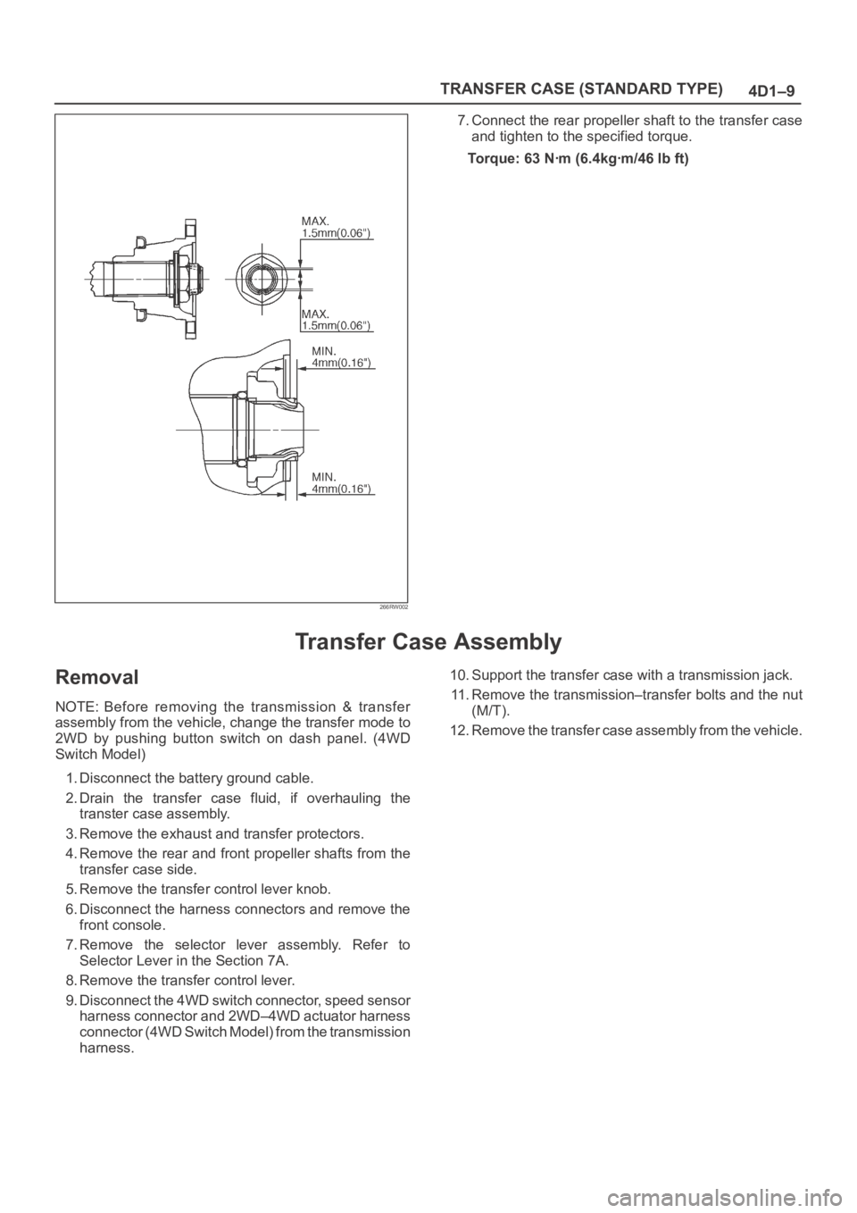
7. Connect the rear propeller shaft to the transfer case
and tighten to the specified torque.
Torque: 63 Nꞏm (6.4kgꞏm/46 lb ft)
Transfer Case Assembly
Removal
NOTE: Before removing the transmission & transfer
assembly from the vehicle, change the transfer mode to
2WD by pushing button switch on dash panel. (4WD
Switch Model)
1. Disconnect the battery ground cable.
2. Drain the transfer case fluid, if overhauling the
transter case assembly.
3. Remove the exhaust and transfer protectors.
4. Remove the rear and front propeller shafts from the
transfer case side.
5. Remove the transfer control lever knob.
6. Disconnect the harness connectors and remove the
front console.
7. Remove the selector lever assembly. Refer to
Selector Lever in the Section 7A.
8. Remove the transfer control lever.
9. Disconnect the 4WD switch connector, speed sensor
harness connector and 2WD–4WD actuator harness
connector (4WD Switch Model) from the transmission
harness.10. Support the transfer case with a transmission jack.
11. Remove the transmission–transfer bolts and the nut
(M/T).
12. Remove the transfer case assembly from the vehicle.
Page 815 of 6000
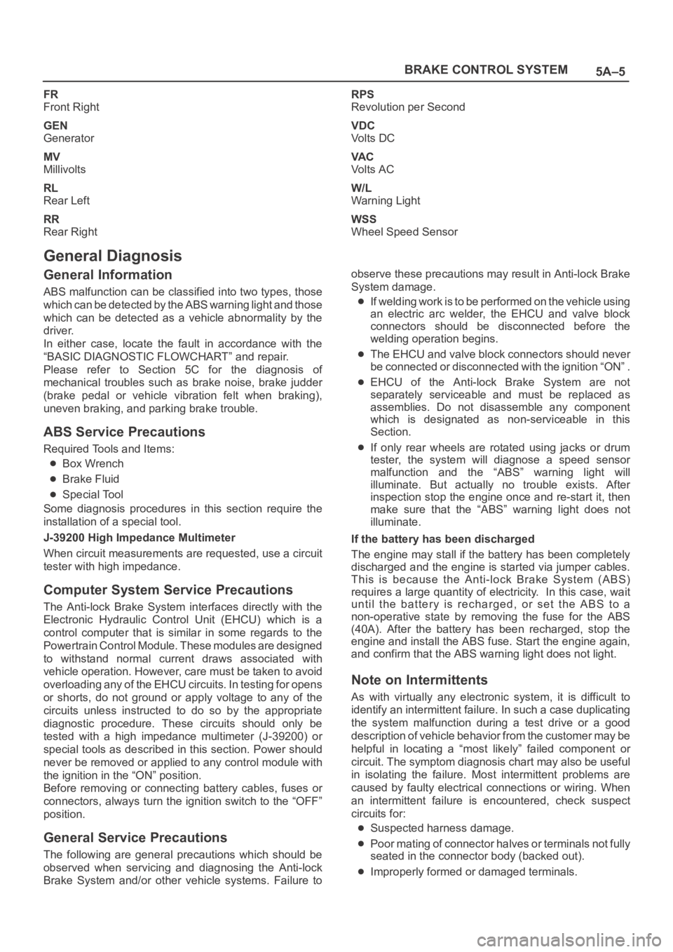
5A–5 BRAKE CONTROL SYSTEM
FR
Front Right
GEN
Generator
MV
Millivolts
RL
Rear Left
RR
Rear RightRPS
Revolution per Second
VDC
Vo l t s D C
VA C
Vo l t s A C
W/L
Warning Light
WSS
Wheel Speed Sensor
General Diagnosis
General Information
ABS malfunction can be classified into two types, those
which can be detected by the ABS warning light and those
which can be detected as a vehicle abnormality by the
driver.
In either case, locate the fault in accordance with the
“BASIC DIAGNOSTIC FLOWCHART” and repair.
Please refer to Section 5C for the diagnosis of
mechanical troubles such as brake noise, brake judder
(brake pedal or vehicle vibration felt when braking),
uneven braking, and parking brake trouble.
ABS Service Precautions
Required Tools and Items:
Box Wrench
Brake Fluid
Special Tool
Some diagnosis procedures in this section require the
installation of a special tool.
J-39200 High Impedance Multimeter
When circuit measurements are requested, use a circuit
tester with high impedance.
Computer System Service Precautions
The Anti-lock Brake System interfaces directly with the
Electronic Hydraulic Control Unit (EHCU) which is a
control computer that is similar in some regards to the
Powertrain Control Module. These modules are designed
to withstand normal current draws associated with
vehicle operation. However, care must be taken to avoid
overloading any of the EHCU circuits. In testing for opens
or shorts, do not ground or apply voltage to any of the
circuits unless instructed to do so by the appropriate
diagnostic procedure. These circuits should only be
tested with a high impedance multimeter (J-39200) or
special tools as described in this section. Power should
never be removed or applied to any control module with
the ignition in the “ON” position.
Before removing or connecting battery cables, fuses or
connectors, always turn the ignition switch to the “OFF”
position.
General Service Precautions
The following are general precautions which should be
observed when servicing and diagnosing the Anti-lock
Brake System and/or other vehicle systems. Failure toobserve these precautions may result in Anti-lock Brake
System damage.
If welding work is to be performed on the vehicle using
an electric arc welder, the EHCU and valve block
connectors should be disconnected before the
welding operation begins.
The EHCU and valve block connectors should never
be connected or disconnected with the ignition “ON” .
EHCU of the Anti-lock Brake System are not
separately serviceable and must be replaced as
assemblies. Do not disassemble any component
which is designated as non-serviceable in this
Section.
If only rear wheels are rotated using jacks or drum
tester, the system will diagnose a speed sensor
malfunction and the “ABS” warning light will
illuminate. But actually no trouble exists. After
inspection stop the engine once and re-start it, then
make sure that the “ABS” warning light does not
illuminate.
If the battery has been discharged
The engine may stall if the battery has been completely
discharged and the engine is started via jumper cables.
This is because the Anti-lock Brake System (ABS)
requires a large quantity of electricity. In this case, wait
until the battery is recharged, or set the ABS to a
non-operative state by removing the fuse for the ABS
(40A). After the battery has been recharged, stop the
engine and install the ABS fuse. Start the engine again,
and confirm that the ABS warning light does not light.
Note on Intermittents
As with virtually any electronic system, it is difficult to
identify an intermittent failure. In such a case duplicating
the system malfunction during a test drive or a good
description of vehicle behavior from the customer may be
helpful in locating a “most likely” failed component or
circuit. The symptom diagnosis chart may also be useful
in isolating the failure. Most intermittent problems are
caused by faulty electrical connections or wiring. When
an intermittent failure is encountered, check suspect
circuits for:
Suspected harness damage.
Poor mating of connector halves or terminals not fully
seated in the connector body (backed out).
Improperly formed or damaged terminals.
Page 821 of 6000
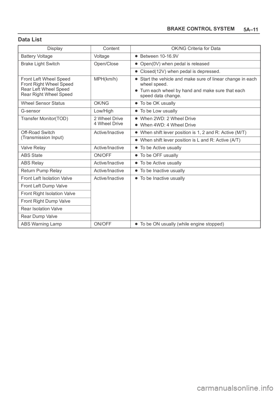
5A–11 BRAKE CONTROL SYSTEM
Data List
DisplayContentOK/NG Criteria for Data
Battery VoltageVo l t a g eBetween 10-16.9V
Brake Light SwitchOpen/CloseOpen(0V) when pedal is released
Closed(12V) when pedal is depressed.
Front Left Wheel Speed
Front Right Wheel Speed
Rear Left Wheel Speed
Rear Right Wheel SpeedMPH(km/h)Start the vehicle and make sure of linear change in each
wheel speed.
Turn each wheel by hand and make sure that each
speed data change.
Wheel Sensor StatusOK/NGTo be OK usually
G-sensorLow/HighTo be Low usually
Transfer Monitor(TOD)2 Wheel Drive
4 Wheel DriveWhen 2WD: 2 Wheel Drive
When 4WD: 4 Wheel Drive
Off-Road Switch
(Transmission Input)
Active/InactiveWhen shift lever position is 1, 2 and R: Active (M/T)
(Transmission Input)When shift lever position is L and R: Active (A/T)
Valve RelayActive/InactiveTo be Active usually
ABS StateON/OFFTo be OFF usually
ABS RelayActive/InactiveTo be Active usually
Return Pump RelayActive/InactiveTo be Inactive usually
Front Left Isolation ValveActive/InactiveTo be Inactive usually
Front Left Dump Valve
Front Right Isolation Valve
Front Right Dump Valve
Rear Isolation Valve
Rear Dump Valve
ABS Warning LampON/OFFTo be ON usually (while engine stopped)