change time OPEL FRONTERA 1998 Owner's Guide
[x] Cancel search | Manufacturer: OPEL, Model Year: 1998, Model line: FRONTERA, Model: OPEL FRONTERA 1998Pages: 6000, PDF Size: 97 MB
Page 1460 of 6000
6E–343 ENGINE DRIVEABILITY AND EMISSIONS
constant measuring and adjusting of the air/fuel ratio, the
fuel injection system is called a “closed loop” system.
The PCM monitors signals from several sensors in order
to determine the fuel needs of the engine. Fuel is
delivered under one of several conditions called “modes.”
All modes are controlled by the PCM.
Fuel Pressure Regulator
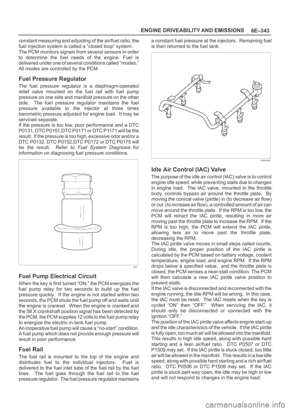
The fuel pressure regulator is a diaphragm-operated
relief valve mounted on the fuel rail with fuel pump
pressure on one side and manifold pressure on the other
side. The fuel pressure regulator maintains the fuel
pressure available to the injector at three times
barometric pressure adjusted for engine load. It may be
serviced separate.
If the pressure is too low, poor performance and a DTC
P0131, DTC P0151,DTC P0171 or DTC P1171 will be the
result. If the pressure is too high, excessive odor and/or a
DTC P0132, DTC P0152,DTC P0172 or DTC P0175 will
be the result. Refer to
Fuel System Diagnosis for
information on diagnosing fuel pressure conditions.
0011
Fuel Pump Electrical Circuit
When the key is first turned “ON,” the PCM energizes the
fuel pump relay for two seconds to build up the fuel
pressure quickly. If the engine is not started within two
seconds, the PCM shuts the fuel pump off and waits until
the engine is cranked. When the engine is cranked and
the 58 X crankshaft position signal has been detected by
the PCM, the PCM supplies 12 volts to the fuel pump relay
to energize the electric in-tank fuel pump.
An inoperative fuel pump will cause a “no-start” condition.
A fuel pump which does not provide enough pressure will
result in poor performance.
Fuel Rail
The fuel rail is mounted to the top of the engine and
distributes fuel to the individual injectors. Fuel is
delivered to the fuel inlet tube of the fuel rail by the fuel
lines. The fuel goes through the fuel rail to the fuel
pressure regulator. The fuel pressure regulator maintainsa constant fuel pressure at the injectors. Remaining fuel
is then returned to the fuel tank.
055RW009
Idle Air Control (IAC) Valve
The purpose of the idle air control (IAC) valve is to control
engine idle speed, while preventing stalls due to changes
in engine load. The IAC valve, mounted in the throttle
body, controls bypass air around the throttle plate. By
moving the conical valve (pintle) in (to decrease air flow)
or out (to increase air flow), a controlled amount of air can
move around the throttle plate. If the RPM is too low, the
PCM will retract the IAC pintle, resulting in more air
moving past the throttle plate to increase the RPM. If the
RPM is too high, the PCM will extend the IAC pintle,
allowing less air to move past the throttle plate,
decreasing the RPM.
The IAC pintle valve moves in small steps called counts.
During idle, the proper position of the IAC pintle is
calculated by the PCM based on battery voltage, coolant
temperature, engine load, and engine RPM. If the RPM
drops below a specified value, and the throttle plate is
closed, the PCM senses a near-stall condition. The PCM
will then calculate a new IAC pintle valve position to
prevent stalls.
If the IAC valve is disconnected and reconnected with the
engine running, the idle RPM will be wrong. In this case,
the IAC must be reset. The IAC resets when the key is
cycled “ON” then “OFF.” When servicing the IAC, it
should only be disconnected or connected with the
ignition “OFF.”
The position of the IAC pintle valve affects engine start-up
and the idle characteristics of the vehicle. If the IAC pintle
is fully open, too much air will be allowed into the manifold.
This results in high idle speed, along with possible hard
starting and a lean air/fuel ratio. DTC P0507 or DTC
P1509 may set. If the IAC pintle is stuck closed, too little
air will be allowed in the manifold. This results in a low idle
speed, along with possible hard starting and a rich air/fuel
ratio. DTC P0506 or DTC P1508 may set. If the IAC
pintle is stuck part-way open, the idle may be high or low
and will not respond to changes in the engine load.
Page 1736 of 6000

ENGINE MECHANICAL 6A – 3
SERVICE INFORMATION
MAIN DATA AND SPECIFICATION
Engine type Diesel, four cycle water cooled inline
Camshaft type DOHC
Number of cylinders 4
Bore x stroke (mm) 95.4 x 104.9
Total piston displacement (cc) 2999
Compression ratio (to 1) 19.0
For Europe : 18.5
Engine weight (dry) N (kg/lb) 2492 (254/560) (A/T)
For Europe : 2422 (247/545) (A/T)
2649 (270/593) (M/T)
For Europe : 2697 (275/606) (M/T)
Engine idling speed (Reference) RPM 720
Compression pressure kpa (kg/cm
2/psi)-rpm 3040 (31/441)-200
Firing order 1–3–4–2
VALVE SYSTEM
Intake valves open at: B.T.D.C. 3°
close at: A.B.D.C. 57.6°
Exhaust valves open at: B.B.D.C. 56.5°
close at: A.T.D.C. 5°
Valve clearance (at cold) mm (in)
intake: 0.15 (0.006)
exhaust: 0.25 (0.01)
Oil filter Full flow and bypass combined type
Oil capacity (Original factory fill or rebuilt engine) 9.0 liters (7.9 US quarts)
Oil capacity (Service change)
with filter change 6.0 liters (6.3 US quarts)
without filter change 5.0 liters (5.3 US quarts)
Oil cooler Water cooled type
Inter cooler Air cooled type
Turbocharger method
Control method Wastegate control
Lubrication Pressurized control
Cooling method Coolant cooled
Crankshaft
As tufftriding (Nitrizing treatment) is applied to increase
crankshaft strength, crankpins and journals should not
be reground.
Piston Cooling
An oiling jet device for piston cooling is provided in the
lubricating oil circuit from the cylinder block oil gallery
via a check valve.
Take care not to damage any oiling jet when removing
and installing piston and connecting assembly.
Fuel Injection System
The injection system is oil rail type.
Quick On Start 4 System
QOS4 preheating system which features a quick-on
glow plug with thermometer control of the glowing time
and the afterglow time function, is applied.
Page 1804 of 6000

ENGINE MECHANICAL 6A – 71
12. Immediately install high pressure oil pipe and
tighten to specified torque.
Torque: 80 Nꞏm (8.1 kgꞏm / 57.9 lb ft)
13. Install cylinder head noise insulator cover.
Refer to “Cylinder Head” in this manual.
14. Install intercooler assembly.
Refer to “Intercooler” in this manual.
15. Install air cleaner cover and air duct.
16. Use TECH2 to rewrite injector data to ECM.
For rewriting method refer to section “Data
Programming in Case of ECM Change” of 6E 4JX1
engine driveability and emissions in this manual.
NOTE:
1) On completion of servicing, bleed air from the
engine inside fuel passage by means of the priming
pump. (The priming pump should be operated more
times than in the case of conventional engines.)
2) As air is in the oil rail, it takes more time to start the
engine. Rough idling may occur while the air is
being bled completely after starting the engine, but
it does not indicate trouble.
The air will be bled and normal engine status will be
reached while the vehicle is driven for about 5 km
or engine is operated for about 5 minutes at 1500 to
2000 rpm.
3) The injector spare part will be provided for group
number B1, B2 and B3 only.
Page 1838 of 6000

ENGINE COOLING 6B – 5
ENGINE COOLANT CHANGE
PROCEDURE
1. To change engine coolant, make sure that the
engine is cool.
WARNING:
When the coolant is heated to a high temperature,
be sure not to loosen or remove the radiator cap.
Otherwise you might get scalded by hot vapor or
boiling water. To open the radiator cap, put a piece
of thick cloth on the cap and loosen the cap slowly
to reduce the pressure once the coolant has
become cooler.
2. Open radiator cap and drain the cooling system by
loosening the drain valve on the radiator and on the
cylinder body.
NOTE: For best results it is suggested that the engine
cooling system be flushed at least once a year. It is
advisable to flush the interior of the cooling system
including the radiator before using anti-freeze
(ethylene-glycol based).
Replace damaged rubber hoses as the engine anti-
freeze coolant is liable to leak out even minor cracks.
Isuzu recommends using Isuzu genuine anti-freeze
(ethylene-glycol based) or equivalent, for the cooling
system and not add any inhibitors or additives.
CAUTION:
A failure to correctly fill the engine cooling system
in changing or topping off coolant may sometimes
cause the coolant to overflow from the filler neck
even before the engine and radiator are completely
full.
If the engine runs under this condition, shortage of
coolant may possibly result in engine overheating.
To avoid such trouble, the following precautions
should be taken in filling the system.
3. To refill engine coolant, pour coolant up to filler neck
using a filling hose which is smaller in outside
diameter than the filler neck. Otherwise air between
the filler neck and the filling hose will block entry,
preventing the system from completely filling up.
4. Keep a filling rate of 9 liter/min. or less. Filling over
this maximum rate may force air inside the engine
and radiator.
And also, the coolant overflow will increase, making
it difficult to determine whether or not the system is
completely full.
5. After filling the system full, pull out the filling hose
and check to see if air trapped in the system is
dislodged and the coolant level goes down. Should
the coolant level go down, repeat topping-off until
there is no more drop in the coolant level.
6. Directly after filling the radiator, fill the reservoir to
the maximum level.
7. Install and tighten radiator cap and start the engine.
After idling for 2 to 3 minutes, stop the engine and
reopen radiator cap. If the water level is lower,
replenish.WARNING:
When the coolant is heated to a high temperature,
be sure not to loosen or remove the radiator cap.
Otherwise you might get scalded by hot vapor or
boiling water. To open the radiator cap, put a piece
of thick cloth on the cap and loosen the cap slowly
to reduce the pressure once the coolant has
become cooler.
8. After tightening radiator cap, warm up the engine at
about 2,000 rpm.
Set heater adjustment to the highest temperature
position, and let the coolant circulate also into
heater water system.
9. Check to see the thermostat has opened by the
needle position of a water thermometer, conduct a
5-minute idle again and stop the engine.
10. When the engine has been cooled, check filler neck
for water level and replenish if required. Should
extreme shortage of coolant be found, check the
coolant system and reservoir tank hose for leakage.
11. Fill the coolant into the reservoir tank up to “MAX”
line.
Page 1856 of 6000

ENGINE FUEL 6C – 11
8. Install injector harness assembly, reconnect
harness connecter to injector.
9. Record the identification marking of injector for
each cylinder that is indicated on the upper portion
of injector.
Legend
(1) Part Number
(2) Category Number (Grade code)
(3) Serial Number
(4) Bar Code
10. Install cylinder head assembly.
Refer to “Cylinder Head” in this manual.
11. Fill with about 300cc of engine oil from the high
pressure oil pipe installation port of the oil rail using
an oil filler.
If assembled without filling the oil rail with oil, the
time for engine starting will be longer.
12. Immediately install high pressure oil pipe and
tighten to specified torque.
Torque: 80 Nꞏm (8.1 kgꞏm / 57.9 lb ft)
13. Install cylinder head noise insulator cover.
Refer to “Cylinder Head” in this manual.
14. Install intercooler assembly.
Refer to “Intercooler” in this manual.
15. Install air cleaner cover and air duct.
16. Use TECH2 to rewrite injector data to ECM.
For rewriting method refer to section “Data
Programming in Case of ECM Change” of section
6E 4JX1 engine driveability and emissions in this
manual.NOTE:
1) On completion of servicing, bleed air from the
engine inside fuel passage by means of the priming
pump. (The priming pump should be operated more
times than in the case of conventional engines.)
2) As air is in the oil rail, it takes more time to start the
engine. Rough idling may occur while the air is
being bled completely after engine start, but it does
not indicate trouble.
The air will be bled and normal engine status will be
reached while the vehicle is driven for about 5 km
or engine is operated for about 5 minutes at 1500 to
2000 rpm.
3) The injector spare part will be provided for group
number B1, B2 and B3 only.
Injector Grade code Programming
(Injector Change)
In case of an injector change, the injector grade code
(category number) must be programmed by Tech-2.
Programming Procedure
1. Connect the Tech-2 to the vehicle DLC.
2. Turn the starter switch to the “ON” position.
3. Select the “Diagnosis” from the Main menu.
4. Select the “Programming” from the Application
menu.
1
4
32
055RW00001
F0 : Diagnostic C ode
F1 : Data Display
F2 : Snapshot
F3 : Miscellaneous Test
F4 : ProgrammingA pplication Menu
035RW00002
Page 1888 of 6000
ENGINE ELECTRICAL 6D – 21
Rectifier Assembly
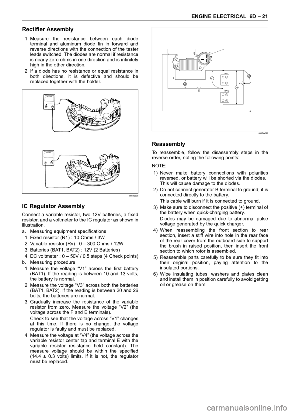
1. Measure the resistance between each diode
terminal and aluminum diode fin in forward and
reverse directions with the connection of the tester
leads switched. The diodes are normal if resistance
is nearly zero ohms in one direction and is infinitely
high in the other direction.
2. If a diode has no resistance or equal resistance in
both directions, it is defective and should be
replaced together with the holder.
IC Regulator Assembly
Connect a variable resistor, two 12V batteries, a fixed
resistor, and a voltmeter to the IC regulator as shown in
illustration.
a. Measuring equipment specifications
1. Fixed resistor (R1) : 10 Ohms / 3W
2. Variable resistor (Rv) : 0 – 300 Ohms / 12W
3. Batteries (BAT1, BAT2) : 12V (2 Batteries)
4. DC voltmeter : 0 – 50V / 0.5 steps (4 Check points)
b. Measuring procedure
1. Measure the voltage “V1” across the first battery
(BAT1). If the reading is between 10 and 13 volts,
the battery is normal.
2. Measure the voltage “V3” across both the batteries
(BAT1, BAT2). If the reading is between 20 and 26
bolts, the batteries are normal.
3. Gradually increase the resistance of the variable
resistor from zero. Measure the voltage “V2” (the
voltage across the F and E terminals).
Check to see that the voltage across “V1” changes
at this time. If there is no change, the voltage
regulator is faulty and must be replaced.
4. Measure the voltage at “V4” (the voltage across the
variable resistor center tap and terminal E with the
variable resistor resistance held constant). The
measure voltage should be within the specified
(14.4 ± 0.3 volts) limits. If it is not, the regulator
must be replaced.
Reassembly
To reassemble, follow the disassembly steps in the
reverse order, noting the following points:
NOTE:
1) Never make battery connections with polarities
reversed, or battery will be shorted via the diodes.
This will cause damage to the diodes.
2) Do not connect generator B terminal to ground; it is
connected directly to the battery.
This cable will burn if it is connected to ground.
3) Make sure to disconnect the positive (+) terminal of
the battery when quick-charging battery.
Diodes may be damaged due to abnormal pulse
voltage generated by the quick charger.
4) When reassembling the front section to rear
section, insert a stiff wire into hole in the rear face
of the rear cover from the outboard side to support
the brush in raised position, then insert the front
section to which rotor is assembled.
5) Reassemble parts carefully to be sure they fit into
their original position, paying attention to the
insulated portions.
6) Wipe insulating tubes, washers and plates clean
and install them in position carefully to avoid getting
oil or grease on them.
066RS036
R
EBS
R1RV
BAT2 BAT1
V2V3
V4V1+
−
+
−
066RW029
Page 1890 of 6000

ENGINE ELECTRICAL 6D – 23
QOS4 PREHEATING SYSTEM
GENERAL DESCRIPTION
QOS4 preheating system features a quick-on glow plug
with thermometer control of the glowing time and the
afterglow time function.
The system consists of the ECM, indicator lamp, ECT
sensor, vehicle speed sensor, relay and temperature
self-control type glow plugs.With the employment of the ECT sensor, the glow time
changes according to the engine coolant temperature,
thus allowing optimum starting conditions to be
obtained.
The after glow time function is controlled by ECM.
NOTE:
Refer to DTC P0380 and P0381 of 6E section.
SYSTEM DIAGRAM
+
-KEY
50A
ECM
50A
GLOW
50A
2
WHT/
RED
0.5
BLK/
BLU
ECM J1-15 3
WHT/
RED
3
RED/
BLKMAIN
80A
8BLK/RED
Glow
Relay
GLOW PLUG 4
BATTHeater & A/C
Relay
060RW132
Page 1918 of 6000
6E–25 4JX1–TC ENGINE DRIVEABILITY AND EMISSIONS
General Service Information
Serviceability Issues
Non-OEM Parts
All of the OBD diagnostics have been calibrated to run
with OEM parts. Accordingly, if commercially sold sensor
or switch is installed, it makes a wrong diagnosis and turn
on the MIL (“Check Engine” lamp).
Aftermarket electronics, such as cellular phones,
stereos, and anti-theft devices, may radiate EMI into the
control system if they are improperly installed. This may
cause a false sensor reading and turn on the MIL (“Check
Engine” lamp).
Poor Vehicle Maintenance
The sensitivity of OBD diagnostics will cause the MIL
(“Check Engine” lamp) to turn on if the vehicle is not
maintained properly. Restricted oil filters, fuel filters, and
crankcase deposits due to lack of oil changes or improper
oil viscosity can trigger actual vehicle faults that were not
previously monitored prior to OBD. Poor vehicle
maintenance can not be classified as a “non-vehicle
fault”, but with the sensitivity of OBD diagnostics, vehicle
maintenance schedules must be more closely followed.
Related System Faults
Many of the OBD system diagnostics will not run if the
ECM detects a fault on a related system or component.
Visual/Physical Engine Compartment
Inspection
Perform a careful visual and physical engine
compartment inspection when performing any diagnostic
procedure or diagnosing the cause of an emission test
failure. This can often lead to repairing a problem without
further steps. Use the following guidelines when
performing a visual/physical inspection:
Inspect all vacuum hoses for punches, cuts,
disconnects, and correct routing.
Inspect hoses that are difficult to see behind other
components.
Inspect all wires in the engine compartment for proper
connections, burned or chafed spots, pinched wires,
contact with sharp edges or contact with hot exhaust
manifolds or pipes.
Basic Knowledge of Tools Required
NOTE: Lack of basic knowledge of this powertrain when
performing diagnostic procedures could result in an
incorrect diagnosis or damage to powertrain
components. Do not attempt to diagnose a powertrain
problem without this basic knowledge.
A basic understanding of hand tools is necessary to effec-
tively use this section of the Service Manual.
Serial Data Communications
Class II Serial Data Communications
This vehicle utilizes the “Class II” communication system.
Each bit of information can have one of two lengths: longor short. This allows vehicle wiring to be reduced by
transmitting and receiving multiple signals over a single
wire. The messages carried on Class II data streams are
also prioritized. If two messages attempt to establish
communications on the data line at the same time, only
the message with higher priority will continue. The device
with the lower priority message must wait.
On this vehicle the Tech 2 displays the actual values for
vehicle parameters. It will not be necessary to perform
any conversions from coded values to actual values.
On-Board Diagnostic (OBD)
On-Board Diagnostic Tests
A diagnostic test is a series of steps, the result of which is
a pass or fail reported to the diagnostic executive. When
a diagnostic test reports a pass result, the diagnostic
executive records the following data:
The diagnostic test has been completed since the last
ignition cycle.
The diagnostic test has passed during the current
ignition cycle.
The fault identified by the diagnostic test is not
currently active.
When a diagnostic test reports a fail result, the diagnostic
executive records the following data:
The diagnostic test has been completed since the last
ignition cycle.
The fault identified by the diagnostic test is currently
active.
The fault has been active during this ignition cycle.
The operating conditions at the time of the failure.
Comprehensive Component Monitor
Diagnostic Operation
Comprehensive component monitoring diagnostics are
required to operate engine properly.
Input Components:
Input components are monitored for circuit continuity and
out-of-range values. This includes rationality checking.
Rationality checking refers to indicating a fault when the
signal from a sensor does not seem reasonable. Accel
Position (AP) sensor that indicates high throttle position
at low engine loads or MAP voltage. Input components
may include, but are not limited to the following sensors:
Intake Air Temperature (IAT) Sensor
Crankshaft Position (CKP) Sensor
Intake throttle Position (ITP) Sensor
Engine Coolant Temperature (ECT) Sensor
Camshaft Position (CMP) Sensor
Manifold absolute Pressure (MAP) Sensor
Accel Position Sensor
Fuel Temp Sensor
Rail Pressure Sensor
Oil Temp Sensor
EGR Pressure Sensor
Vehicle Speed Sensor
Page 1925 of 6000
6E–32
4JX1–TC ENGINE DRIVEABILITY AND EMISSIONS
DTC Modes
There are three options available in the Tech 2 DTC mode
to display the enhanced information available. A
description of the new modes, DTC Info, follows. After
selecting DTC, the following menu appears:
DTC Info
Clear Info
Read DTC Info Ordered By Priority
The following is a brief description of each of the sub
menus in DTC Info. The order in which they appear here is
alphabetical and not necessarily the way they will appear
on the Tech 2.
DTC Information Mode
Use the DTC info mode to search for a specific type of
stored DTC information.The service manual may instruct
the technician to test for DTCs in a certain manner.
Always follow published service procedures.
Fail This Ignition
This selection will display all DTCs that have failed during
the present ignition cycle.
History
This selection will display only D T C s t h a t a r e s t o r e d i n t h e
ECM’s history memory. It will not display Type B DTCs
that have not requested the MIL (“Check Engine” lamp). It
will display all type A and B DTCs that have requested the
MIL and have failed within the last 40 warm-up cycles. In
addition, it will display all type C and type D DTCs that
have failed within the last 40 warm-up cycles.
MIL SVC or Message Requested
This selection will display only DTCs that are requesting
the MIL. Type C and type D DTCs cannot be displayed
using this option. This selection will report type B DTCs
only after the MIL has been requested.
Test Failed Since Code Cleared
This selection will display all active and history DTCs that
have reported a test failure since the last time DTCs were
cleared.
Injector Test
This test is conducted to make it sure that appropriate
electric signals are being sent to injectors Nos. 1 – 4.
Tech–2 must be used for this test.
Test Procedure:
1. Connect Tech–2 to the vehicle DLC.
2. Set Ignition Switch to the “ON” position.
3. Select Control Test.
4. Select Injector Test.
5. Send instructions to each injector(Switch on), making
sure of injector working noise.
NOTE: If injector working noise (Clink) can hardly be
confirmed, remove the engine head cover noise
insulation.
Refer to Section 6A.6. In the injector whose working noise has been
confirmed, its electric circuit can be regarded as
normal.
As for the injector whose working noise has not been
confirmed, its electric circuit or the injector proper is
faulty.
EGR Valve Test
This test is conducted to check EGR valve for its working.
This test needs Tech–2.
Test Procedure
1. Connect Tech–2 to vehicle DLC.
2. Switch on the engine.
3. Select “DIAGNOSIS” from the main menu.
4. Select Miscellaneous Test.
5. Select EGR Valve.
6. Instruct EGR Valve to check a data list.
7. If change in the data list shows a normal valve, the
working of EGR Valve can be judged to be normal.
Rail Pressure Control Valve Test
This test is conducted to check RPC valve for its working.
This test needs Tech–2.
Test Procedure
1. Connect Tech–2 to vehicle DLC.
2. Switch on the engine.
3. Select “DIAGNOSIS” from the main menu.
4. Select Miscellaneous Test.
5. Select Rail Pressure Control Valve.
6. Instruct RPC Valve to check a data list.
7. If change in the data list shows a normal valve, the
working of RPC Valve can be judged to be normal.
Injector Balance Test
This test is conducted to make it sure that appropriate
electric signals are being sent to injectors Nos. 1-4, when
the engine is idling.
This test needs Tech–2.
Test Procedure
1. Connect Tech–2 to vehicle DLC.
2. The engine is running at idling condition.
3. Select “DIAGNOSIS” from the main menu.
4. Select Miscellaneous Test.
5. Select the injector Balance Test.
6. Send instructions to each injector(Switch On),
making sure change of the engine vibration.
7. In the injector whose change of the vibration has been
confirmed, it’s electric circuit can be regarded as
normal.
Data Programming in Case of ECM Change
When replacing ECM, it is necessary to confirm and
record the group sign of injector beforehand. For this
confirmation.
Page 1934 of 6000
6E–41 4JX1–TC ENGINE DRIVEABILITY AND EMISSIONS
EGR (Exhaust Gas Recirculation)
Diagnosis
A diagnosis of the EGR system is covered by DTC
P1403.
EGR VSV circuit diagnosis is covered by DTC P1404.
EGR pressure sensor diagnosis is covered by DTC
P405 and/or P406.
EGR EVRV circuit diagnosis is covered by DTC
P1405. Refer to the DTC charts.
Tech 2 Data Definitions and Ranges
A/C CLUTCH–Tech 2 Displays ON or OFF–
Indicates whether the A/C has commanded the A/C
clutch ON.
MAP kPa — Tech 2 Range 10-105 kPa/0.00-5.00
Vo l t s —
The manifold absolute pressure reading is determined
from the MAP sensor signal monitored during key up and
wide open throttle (WOT) conditions. The manifold
absolute pressure is used to compensate for altitude
differences and is normally displayed around “61-104”
depending on altitude and manifold absolute pressure.
CMP ACT. COUNTER –Cam Position
DESIRED IDLE — Tech 2 Range 0-3187 RPM —
The idle speed that the ECM is commanding. The ECM
will compensate for various engine loads based on engine
coolant temperature, to keep the engine at the desired
speed.
ECT — (Engine Coolant Temperature) Tech 2
Range –40
C to 151C (–40F to 304F) —
The engine coolant temperature (ECT) is mounted in the
coolant stream and sends engine temperature
information to the ECM. The ECM applies 5 volts to the
ECT sensor circuit. The sensor is a thermistor which
changes internal resistance as temperature changes.
When the sensor is cold (high resistance), the ECM
monitors a high signal voltage and interprets that as a cold
engine. As the sensor warms (decreasing resistance),
the voltage signal will decrease and the ECM will interpret
the lower voltage as a warm engine.
ENGINE RUN TIME — Tech 2 Range
00:00:00-99:99:99 Hrs:Min:Sec —
Indicates the time elapsed since the engine was started.
If the engine is stopped, engine run time will be reset to
00:00:00.
ENGINE SPEED — Range 0-9999 RPM —
Engine speed is computed by the ECM from the 57X
reference input. It should remain close to desired idle
under various engine loads with engine idling.Air Intake Valve meter POSITION — Tech 2 Range
0-100 % —
IAT (INTAKE AIR TEMPERATURE)— Tech 2 Range
–40
C to 151C (–40F to 304F) —
The ECM converts the resistance of the intake air
temperature sensor to degrees. Intake air temperature
(IAT) is used by the ECM to adjust fuel delivery and spark
timing according to incoming air density.
MAP — Tech 2 Range 10-105 kPa (0.00-4.97 Volts)—
The manifold absolute pressure (MAP) sensor measures
the change in the boost pressure.
MIL — Tech 2 Displays ON or OFF —
Indicates the ECM commanded state of the malfunction
indicator lamp.
AP — Tech 2 Range 0%-100% —
AP (Accelerator position) angle is computed by the ECM
from the AP sensor voltage. AP angle should display
“0%” at idle and “100%” at wide open throttle.
AP SENSOR — Tech 2 Range 0.00-5.00 Volts —
The voltage being monitored by the ECM on the AP
sensor signal circuit.
VEHICLE SPEED—Tech 2 Range 0-255 km/h (0-155
mph)–
The vehicle speed sensor signal is converted into km/h
and mph for display.
Typical Scan Data Values
Use the Typical Scan Data Values Table only after the
On-Board Diagnostic System Check has been
completed, no DTC(s) were noted, and you have
determined that the on-board diagnostics are functioning
properly. Tech 2 values from a properly-running engine
may be used for comparison with the engine you are
diagnosing. The typical scan data values represent
values that would be seen on a normally-running engine.
NOTE: A Tech 2 that displays faulty data should not be
used, and the problem should be reported to the Tech 2
manufacturer. Use of a faulty Tech 2 can result in
misdiagnosis and unnecessary replacement of parts.
Only the parameters listed below are referred to in this
service manual for use in diagnosis. For further
information on using the Tech 2 to diagnose the ECM and
related sensors, refer to the applicable reference section
listed below. If all values are within the typical range
described below, refer to the
Symptoms section for
diagnosis.
Test Conditions
Engine running, lower radiator hose hot, transmission in
park or neutral, accessaries off, brake not applied and air
conditioning off.