check oil OPEL FRONTERA 1998 Owner's Guide
[x] Cancel search | Manufacturer: OPEL, Model Year: 1998, Model line: FRONTERA, Model: OPEL FRONTERA 1998Pages: 6000, PDF Size: 97 MB
Page 793 of 6000
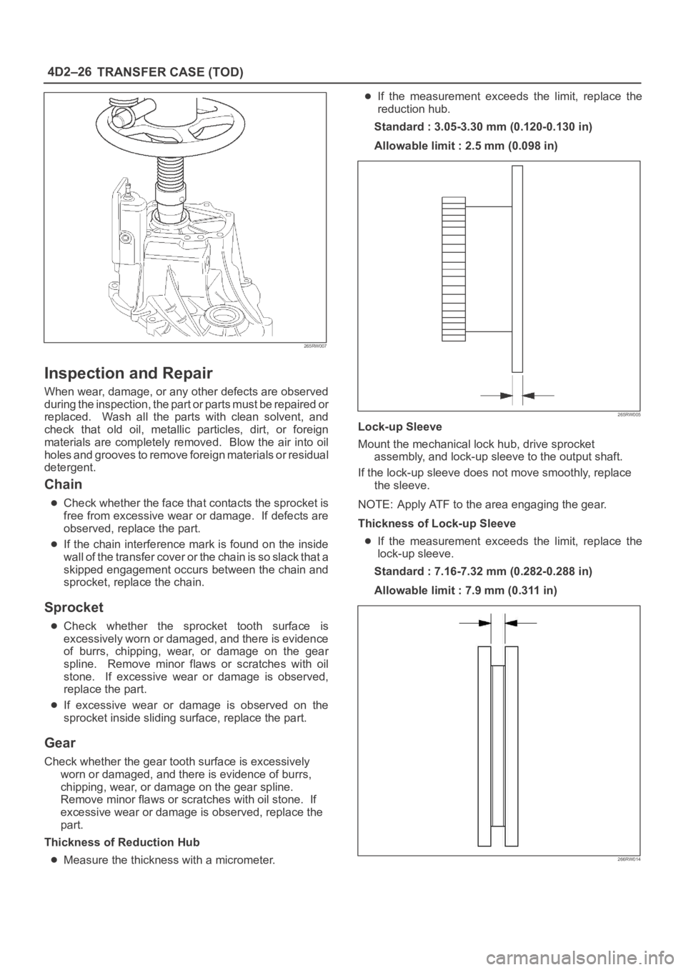
4D2–26
TRANSFER CASE (TOD)
265RW007
Inspection and Repair
When wear, damage, or any other defects are observed
during the inspection, the part or parts must be repaired or
replaced. Wash all the parts with clean solvent, and
check that old oil, metallic particles, dirt, or foreign
materials are completely removed. Blow the air into oil
holes and grooves to remove foreign materials or residual
detergent.
Chain
Check whether the face that contacts the sprocket is
free from excessive wear or damage. If defects are
observed, replace the part.
If the chain interference mark is found on the inside
w a l l o f t h e t r a n s f e r c o v e r o r t h e c h a i n i s s o s l a c k t h a t a
skipped engagement occurs between the chain and
sprocket, replace the chain.
Sprocket
Check whether the sprocket tooth surface is
excessively worn or damaged, and there is evidence
of burrs, chipping, wear, or damage on the gear
spline. Remove minor flaws or scratches with oil
stone. If excessive wear or damage is observed,
replace the part.
If excessive wear or damage is observed on the
sprocket inside sliding surface, replace the part.
Gear
Check whether the gear tooth surface is excessively
worn or damaged, and there is evidence of burrs,
chipping, wear, or damage on the gear spline.
Remove minor flaws or scratches with oil stone. If
excessive wear or damage is observed, replace the
part.
Thickness of Reduction Hub
Measure the thickness with a micrometer.
If the measurement exceeds the limit, replace the
reduction hub.
Standard : 3.05-3.30 mm (0.120-0.130 in)
Allowable limit : 2.5 mm (0.098 in)
265RW005
Lock-up Sleeve
Mount the mechanical lock hub, drive sprocket
assembly, and lock-up sleeve to the output shaft.
If the lock-up sleeve does not move smoothly, replace
the sleeve.
NOTE: Apply ATF to the area engaging the gear.
Thickness of Lock-up Sleeve
If the measurement exceeds the limit, replace the
lock-up sleeve.
Standard : 7.16-7.32 mm (0.282-0.288 in)
Allowable limit : 7.9 mm (0.311 in)
266RW014
Page 795 of 6000
4D2–28
TRANSFER CASE (TOD)
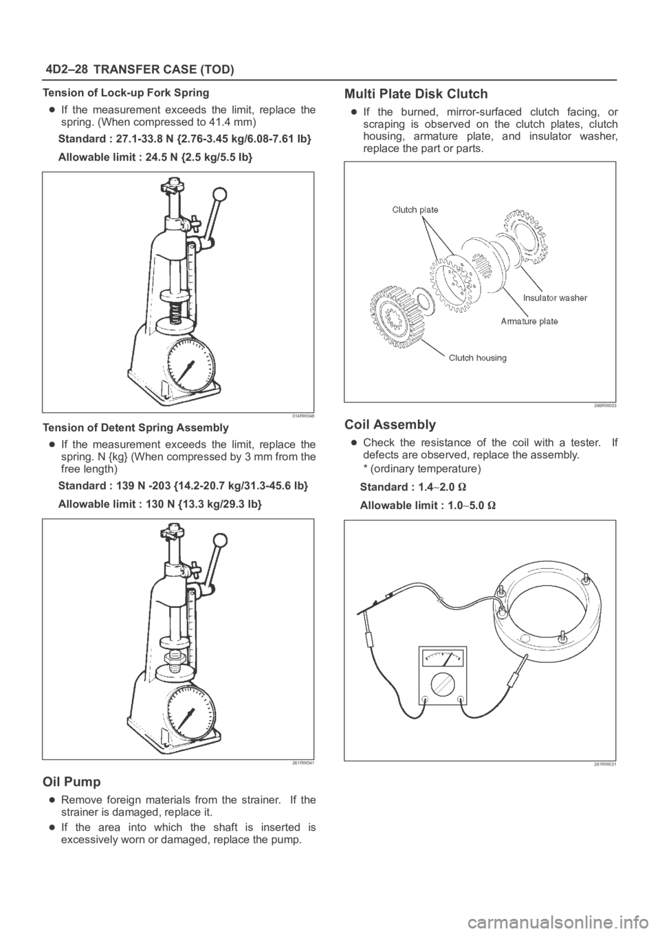
Tension of Lock-up Fork Spring
If the measurement exceeds the limit, replace the
spring. (When compressed to 41.4 mm)
Standard : 27.1-33.8 N {2.76-3.45 kg/6.08-7.61 Ib}
Allowable limit : 24.5 N {2.5 kg/5.5 Ib}
014RW048
Tension of Detent Spring Assembly
If the measurement exceeds the limit, replace the
spring. N {kg} (When compressed by 3 mm from the
free length)
Standard : 139 N -203 {14.2-20.7 kg/31.3-45.6 Ib}
Allowable limit : 130 N {13.3 kg/29.3 Ib}
261RW041
Oil Pump
Remove foreign materials from the strainer. If the
strainer is damaged, replace it.
If the area into which the shaft is inserted is
excessively worn or damaged, replace the pump.
Multi Plate Disk Clutch
If the burned, mirror-surfaced clutch facing, or
scraping is observed on the clutch plates, clutch
housing, armature plate, and insulator washer,
replace the part or parts.
266RW003
Coil Assembly
Check the resistance of the coil with a tester. If
defects are observed, replace the assembly.
* (ordinary temperature)
Standard : 1.4
2.0
Allowable limit : 1.05.0
261RW031
Page 796 of 6000
4D2–29 TRANSFER CASE (TOD)
Cam Pulley, Cam Ball, and Cam&Coil
Housing
Check the cam balls and cam for excessive wear or
damage. If defective, replace the parts. 4H and 4L
switches.
266RW016
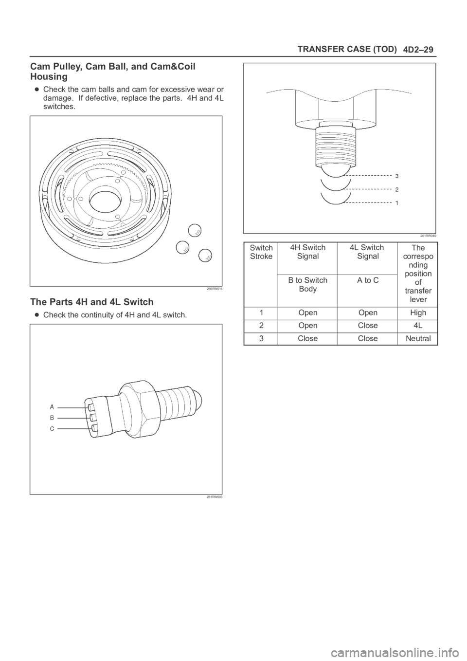
The Parts 4H and 4L Switch
Check the continuity of 4H and 4L switch.
261RW003
261RW049
Switch
Stroke4H Switch
Signal4L Switch
SignalThe
correspo
nding
p
ositionB to Switch
BodyA to Cosition
of
transfer
lever
1OpenOpenHigh
2OpenClose4L
3CloseCloseNeutral
Page 814 of 6000
5A–4
BRAKE CONTROL SYSTEM
normal braking when a malfunction has occurred in the
ABS.
The EHCU has a self-diagnosing function which can
indicate faulty circuits during diagnosis.
The EHCU is mounted on the engine compartment front
right side. It consists of a Motor, Plunger Pump, Solenoid
Valves and Check Valve.
On the outside, the relay box containing a motor relay and
a valve relay is installed.
Solenoid Valves: Reduces or holds the caliper fluid
pressure for each front disc brake or both rear disc brakes
according to the signal sent from the EHCU.
Reservoir: Temporarily holds the brake fluid that returns
from the front and rear disc brake caliper so that pressure
of front disc brake caliper can be reduced smoothly.
Plunger Pump: Feeds the brake fluid held in the reservoir
to the master cylinder.
Motor: Drives the pump according to the signal from
EHCU.
Check Valve: Controls the brake fluid flow.
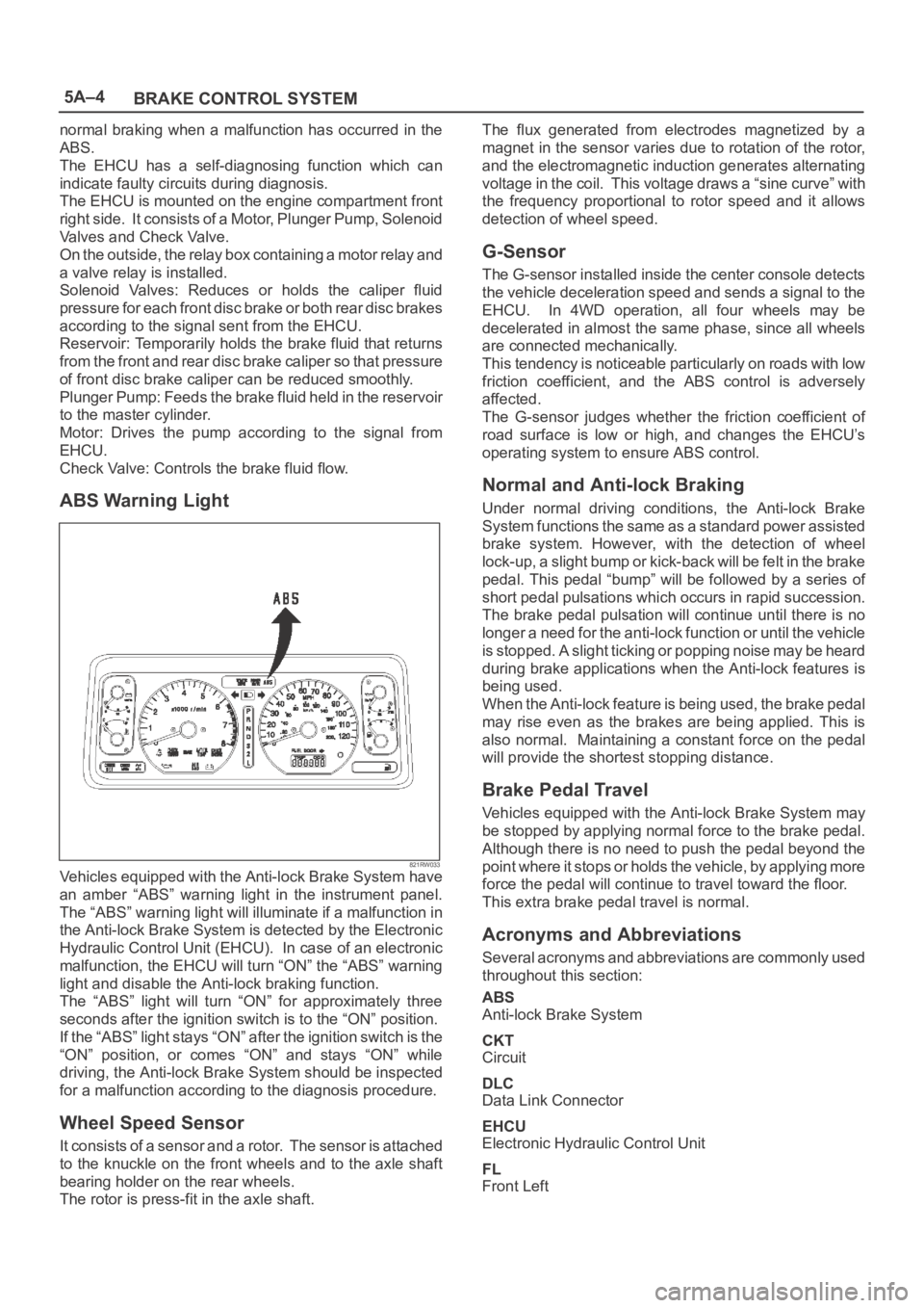
ABS Warning Light
821RW033Vehicles equipped with the Anti-lock Brake System have
an amber “ABS” warning light in the instrument panel.
The “ABS” warning light will illuminate if a malfunction in
the Anti-lock Brake System is detected by the Electronic
Hydraulic Control Unit (EHCU). In case of an electronic
malfunction, the EHCU will turn “ON” the “ABS” warning
light and disable the Anti-lock braking function.
The “ABS” light will turn “ON” for approximately three
seconds after the ignition switch is to the “ON” position.
If the “ABS” light stays “ON” after the ignition switch is the
“ON” position, or comes “ON” and stays “ON” while
driving, the Anti-lock Brake System should be inspected
for a malfunction according to the diagnosis procedure.
Wheel Speed Sensor
It consists of a sensor and a rotor. The sensor is attached
to the knuckle on the front wheels and to the axle shaft
bearing holder on the rear wheels.
The rotor is press-fit in the axle shaft.The flux generated from electrodes magnetized by a
magnet in the sensor varies due to rotation of the rotor,
and the electromagnetic induction generates alternating
voltage in the coil. This voltage draws a “sine curve” with
the frequency proportional to rotor speed and it allows
detection of wheel speed.
G-Sensor
The G-sensor installed inside the center console detects
the vehicle deceleration speed and sends a signal to the
EHCU. In 4WD operation, all four wheels may be
decelerated in almost the same phase, since all wheels
are connected mechanically.
This tendency is noticeable particularly on roads with low
friction coefficient, and the ABS control is adversely
affected.
The G-sensor judges whether the friction coefficient of
road surface is low or high, and changes the EHCU’s
operating system to ensure ABS control.
Normal and Anti-lock Braking
Under normal driving conditions, the Anti-lock Brake
System functions the same as a standard power assisted
brake system. However, with the detection of wheel
lock-up, a slight bump or kick-back will be felt in the brake
pedal. This pedal “bump” will be followed by a series of
short pedal pulsations which occurs in rapid succession.
The brake pedal pulsation will continue until there is no
longer a need for the anti-lock function or until the vehicle
is stopped. A slight ticking or popping noise may be heard
during brake applications when the Anti-lock features is
being used.
When the Anti-lock feature is being used, the brake pedal
may rise even as the brakes are being applied. This is
also normal. Maintaining a constant force on the pedal
will provide the shortest stopping distance.
Brake Pedal Travel
Vehicles equipped with the Anti-lock Brake System may
be stopped by applying normal force to the brake pedal.
Although there is no need to push the pedal beyond the
point where it stops or holds the vehicle, by applying more
force the pedal will continue to travel toward the floor.
This extra brake pedal travel is normal.
Acronyms and Abbreviations
Several acronyms and abbreviations are commonly used
throughout this section:
ABS
Anti-lock Brake System
CKT
Circuit
DLC
Data Link Connector
EHCU
Electronic Hydraulic Control Unit
FL
Front Left
Page 961 of 6000
6A–5
ENGINE MECHANICAL
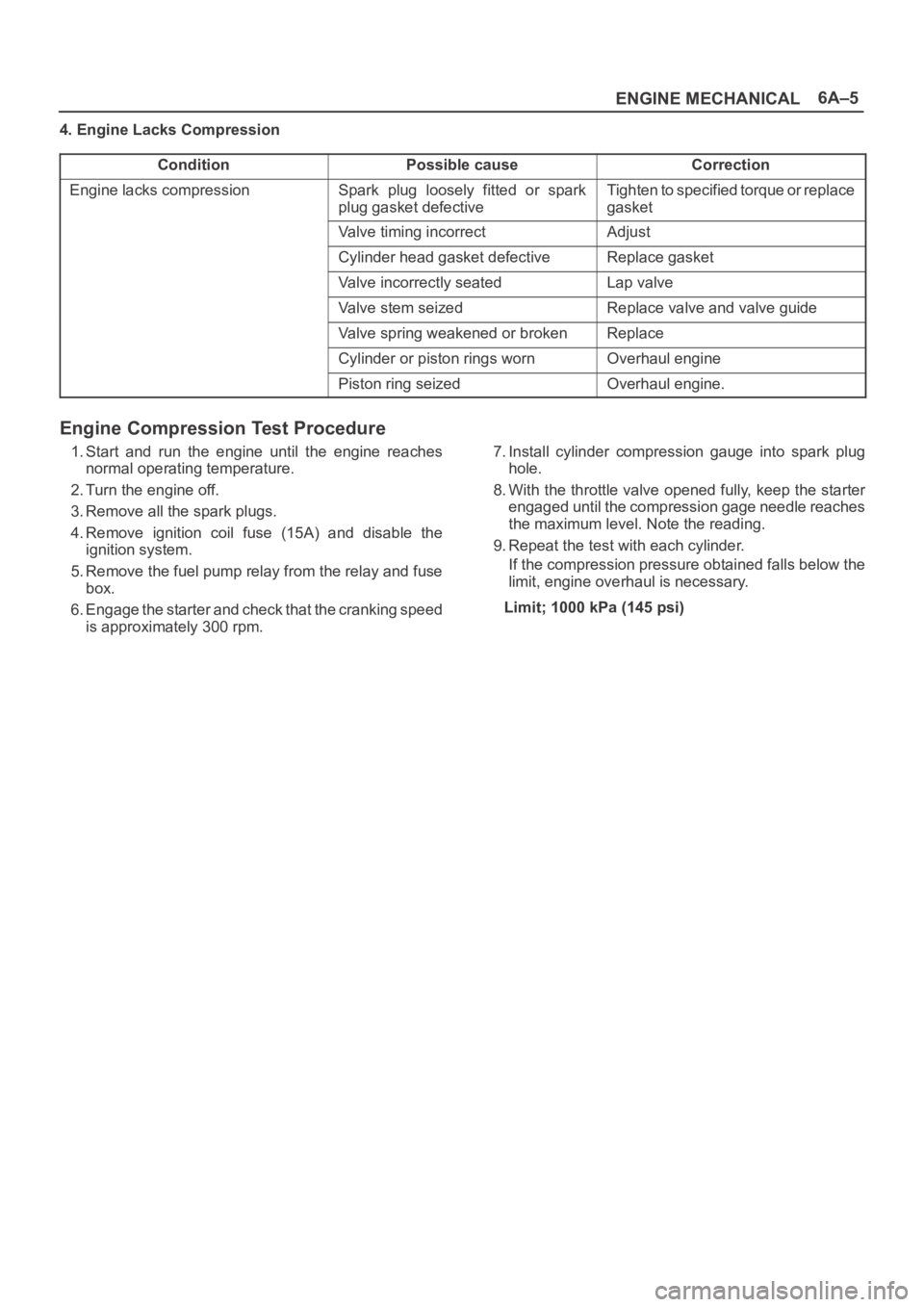
4. Engine Lacks Compression
Condition
Possible causeCorrection
Engine lacks compressionSpark plug loosely fitted or spark
plug gasket defectiveTighten to specified torque or replace
gasket
Valve timing incorrectAdjust
Cylinder head gasket defectiveReplace gasket
Valve incorrectly seatedLap valve
Valve stem seizedReplace valve and valve guide
Valve spring weakened or brokenReplace
Cylinder or piston rings wornOverhaul engine
Piston ring seizedOverhaul engine.
Engine Compression Test Procedure
1. Start and run the engine until the engine reaches
normal operating temperature.
2. Turn the engine off.
3. Remove all the spark plugs.
4. Remove ignition coil fuse (15A) and disable the
ignition system.
5. Remove the fuel pump relay from the relay and fuse
box.
6. Engage the starter and check that the cranking speed
is approximately 300 rpm.7. Install cylinder compression gauge into spark plug
hole.
8. With the throttle valve opened fully, keep the starter
engaged until the compression gage needle reaches
the maximum level. Note the reading.
9. Repeat the test with each cylinder.
If the compression pressure obtained falls below the
limit, engine overhaul is necessary.
Limit; 1000 kPa (145 psi)
Page 972 of 6000
6A–16
ENGINE MECHANICAL
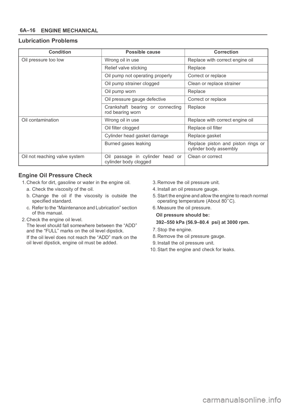
Lubrication Problems
ConditionPossible causeCorrection
Oil pressure too lowWrong oil in useReplace with correct engine oil
Relief valve stickingReplace
Oil pump not operating properlyCorrect or replace
Oil pump strainer cloggedClean or replace strainer
Oil pump wornReplace
Oil pressure gauge defectiveCorrect or replace
Crankshaft bearing or connecting
rod bearing wornReplace
Oil contaminationWrong oil in useReplace with correct engine oil
Oil filter cloggedReplace oil filter
Cylinder head gasket damageReplace gasket
Burned gases leakingReplace piston and piston rings or
cylinder body assembly
Oil not reaching valve systemOil passage in cylinder head or
cylinder body cloggedClean or correct
Engine Oil Pressure Check
1. Check for dirt, gasoline or water in the engine oil.
a. Check the viscosity of the oil.
b. Change the oil if the viscosity is outside the
specified standard.
c. Refer to the “Maintenance and Lubrication” section
of this manual.
2. Check the engine oil level.
The level should fall somewhere between the “ADD”
and the “FULL” marks on the oil level dipstick.
If the oil level does not reach the “ADD” mark on the
oil level dipstick, engine oil must be added.3. Remove the oil pressure unit.
4. Install an oil pressure gauge.
5. Start the engine and allow the engine to reach normal
operating temperature (About 80
C).
6. Measure the oil pressure.
Oil pressure should be:
392–550 kPa (56.9–80.4 psi) at 3000 rpm.
7. Stop the engine.
8. Remove the oil pressure gauge.
9. Install the oil pressure unit.
10. Start the engine and check for leaks.
Page 1014 of 6000
6A–58
ENGINE MECHANICAL
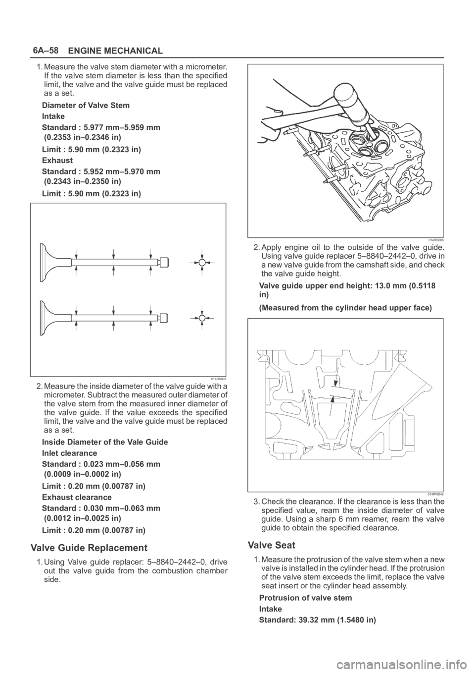
1. Measure the valve stem diameter with a micrometer.
If the valve stem diameter is less than the specified
limit, the valve and the valve guide must be replaced
as a set.
Diameter of Valve Stem
Intake
Standard : 5.977 mm–5.959 mm
(0.2353 in–0.2346 in)
Limit : 5.90 mm (0.2323 in)
Exhaust
Standard : 5.952 mm–5.970 mm
(0.2343 in–0.2350 in)
Limit : 5.90 mm (0.2323 in)
014RS007
2. Measure the inside diameter of the valve guide with a
micrometer. Subtract the measured outer diameter of
the valve stem from the measured inner diameter of
the valve guide. If the value exceeds the specified
limit, the valve and the valve guide must be replaced
as a set.
Inside Diameter of the Vale Guide
Inlet clearance
Standard : 0.023 mm–0.056 mm
(0.0009 in–0.0002 in)
Limit : 0.20 mm (0.00787 in)
Exhaust clearance
Standard : 0.030 mm–0.063 mm
(0.0012 in–0.0025 in)
Limit : 0.20 mm (0.00787 in)
Valve Guide Replacement
1. Using Valve guide replacer: 5–8840–2442–0, drive
out the valve guide from the combustion chamber
side.
014RS008
2. Apply engine oil to the outside of the valve guide.
Using valve guide replacer 5–8840–2442–0, drive in
a new valve guide from the camshaft side, and check
the valve guide height.
Valve guide upper end height: 13.0 mm (0.5118
in)
(Measured from the cylinder head upper face)
014RW046
3. Check the clearance. If the clearance is less than the
specified value, ream the inside diameter of valve
guide. Using a sharp 6 mm reamer, ream the valve
guide to obtain the specified clearance.
Va l v e S e a t
1. Measure the protrusion of the valve stem when a new
valve is installed in the cylinder head. If the protrusion
of the valve stem exceeds the limit, replace the valve
seat insert or the cylinder head assembly.
Protrusion of valve stem
Intake
Standard: 39.32 mm (1.5480 in)
Page 1016 of 6000
6A–60
ENGINE MECHANICAL
6. Check that the valve contact width is correct.
7. Check that the valve seat insert surface is in contact
with the entire circumference of the valve.
014RS014
Valve Seat Insert Replacement
1. Arc weld the rod at several points. Be careful not to
damage the aluminum section.
2. Allow the rod to cool for a few minutes. This will cause
the valve seat to shrink.
3. Strike the rod and pull it out.
014RS015
4. Carefully clean the valve seat press–fit section on the
cylinder head side.
5. Heat the press–fit section with steam or some other
means to cause expansion. Cool the valve seat with
dry ice or some other means.
6. Insert the press–fit section into the valve seat
horizontally.
Standard fitting interference: 0.14 mm–0.09 mm
(0.0055 in–0.0035 in)7. After insertion, use a seat grinder to grind finish the
seating face. Carefully note the seating angle, the
contact width, and the depression.
8. Lap the valve and the seat.
Reassembly
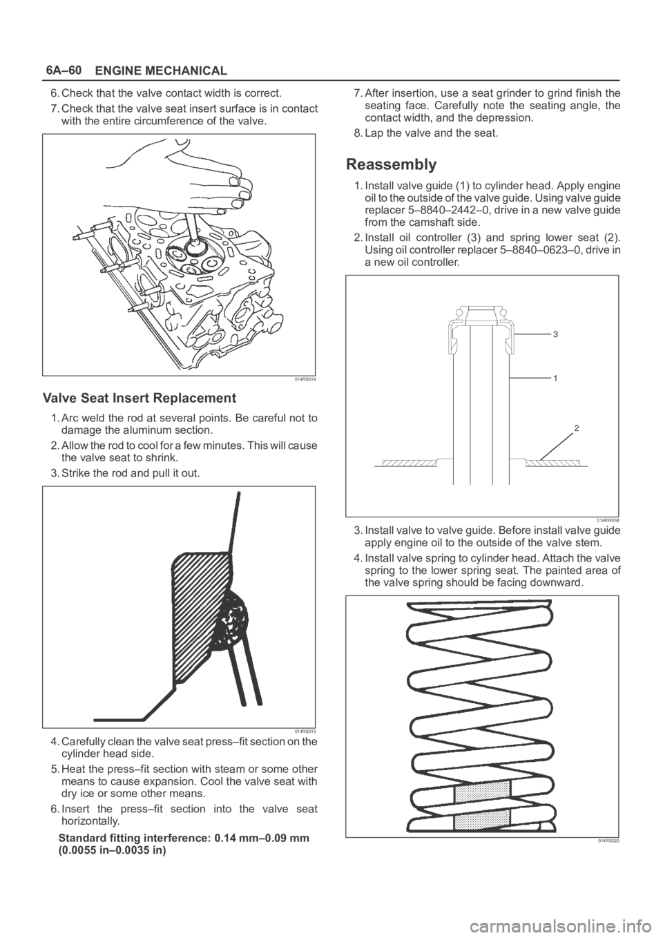
1. Install valve guide (1) to cylinder head. Apply engine
oil to the outside of the valve guide. Using valve guide
replacer 5–8840–2442–0, drive in a new valve guide
from the camshaft side.
2. Install oil controller (3) and spring lower seat (2).
Using oil controller replacer 5–8840–0623–0, drive in
a new oil controller.
014RW058
3. Install valve to valve guide. Before install valve guide
apply engine oil to the outside of the valve stem.
4. Install valve spring to cylinder head. Attach the valve
spring to the lower spring seat. The painted area of
the valve spring should be facing downward.
014RS020
Page 1017 of 6000
6A–61
ENGINE MECHANICAL
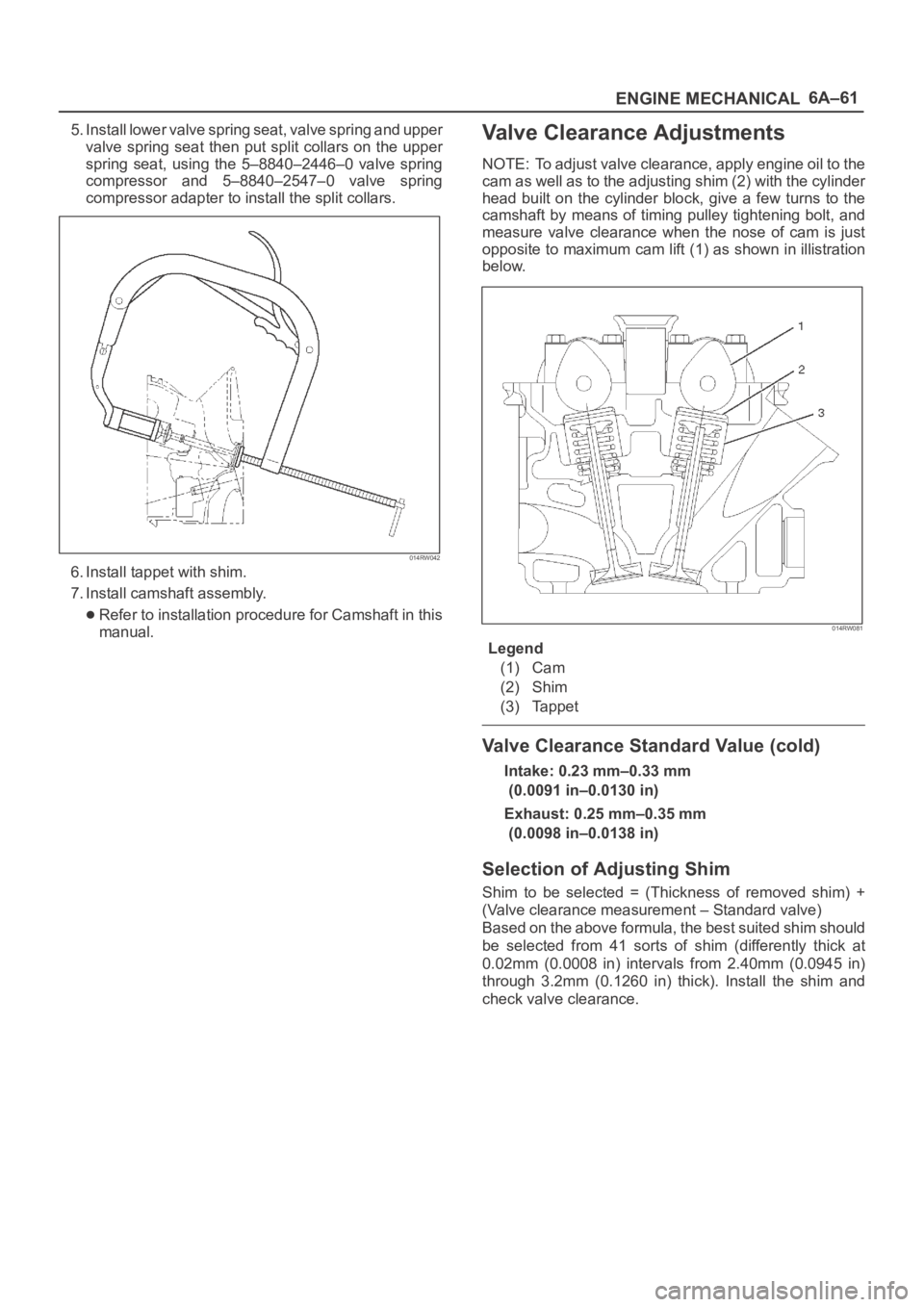
5. Install lower valve spring seat, valve spring and upper
valve spring seat then put split collars on the upper
spring seat, using the 5–8840–2446–0 valve spring
compressor and 5–8840–2547–0 valve spring
compressor adapter to install the split collars.
014RW042
6. Install tappet with shim.
7. Install camshaft assembly.
Refer to installation procedure for Camshaft in this
manual.
Valve Clearance Adjustments
NOTE: To adjust valve clearance, apply engine oil to the
cam as well as to the adjusting shim (2) with the cylinder
head built on the cylinder block, give a few turns to the
camshaft by means of timing pulley tightening bolt, and
measure valve clearance when the nose of cam is just
opposite to maximum cam lift (1) as shown in illistration
below.
014RW081
Legend
(1) Cam
(2) Shim
(3) Tappet
Valve Clearance Standard Value (cold)
Intake: 0.23 mm–0.33 mm
(0.0091 in–0.0130 in)
Exhaust: 0.25 mm–0.35 mm
(0.0098 in–0.0138 in)
Selection of Adjusting Shim
Shim to be selected = (Thickness of removed shim) +
(Valve clearance measurement – Standard valve)
Based on the above formula, the best suited shim should
be selected from 41 sorts of shim (differently thick at
0.02mm (0.0008 in) intervals from 2.40mm (0.0945 in)
through 3.2mm (0.1260 in) thick). Install the shim and
check valve clearance.
Page 1026 of 6000
6A–70
ENGINE MECHANICAL
7. Remove oil gallery (7).
8. Remove piston and connecting rod assembly (8).
Refer to “Piston, Piston Ring and Connecting Rod” in
this manual.
9. Remove flywheel (9).
10. Remove rear oil seal retainer (10).
11. Remove main bearing cap (11).
12. Remove crankshaft (12).
Inspection and Repair
1. Crankshaft
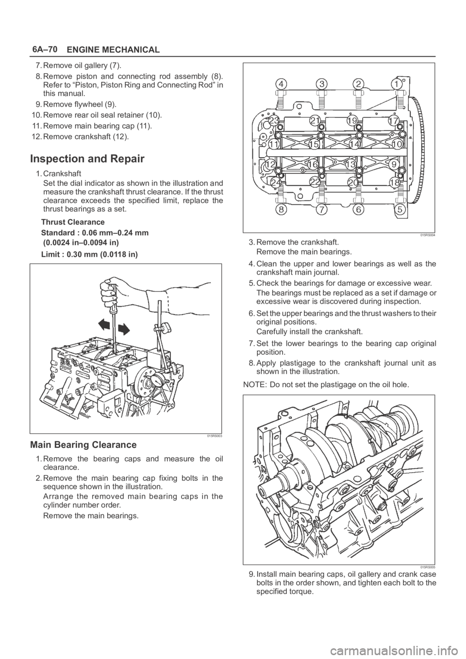
Set the dial indicator as shown in the illustration and
measure the crankshaft thrust clearance. If the thrust
clearance exceeds the specified limit, replace the
thrust bearings as a set.
Thrust Clearance
Standard : 0.06 mm–0.24 mm
(0.0024 in–0.0094 in)
Limit : 0.30 mm (0.0118 in)
015RS003
Main Bearing Clearance
1. Remove the bearing caps and measure the oil
clearance.
2. Remove the main bearing cap fixing bolts in the
sequence shown in the illustration.
Arrange the removed main bearing caps in the
cylinder number order.
Remove the main bearings.
015RS004
3. Remove the crankshaft.
Remove the main bearings.
4. Clean the upper and lower bearings as well as the
crankshaft main journal.
5. Check the bearings for damage or excessive wear.
The bearings must be replaced as a set if damage or
excessive wear is discovered during inspection.
6. Set the upper bearings and the thrust washers to their
original positions.
Carefully install the crankshaft.
7. Set the lower bearings to the bearing cap original
position.
8. Apply plastigage to the crankshaft journal unit as
shown in the illustration.
NOTE: Do not set the plastigage on the oil hole.
015RS005
9. Install main bearing caps, oil gallery and crank case
bolts in the order shown, and tighten each bolt to the
specified torque.