check oil OPEL FRONTERA 1998 User Guide
[x] Cancel search | Manufacturer: OPEL, Model Year: 1998, Model line: FRONTERA, Model: OPEL FRONTERA 1998Pages: 6000, PDF Size: 97 MB
Page 524 of 6000
DIFFERENTIAL (REAR 244mm)
4A2B–21
Disassembly
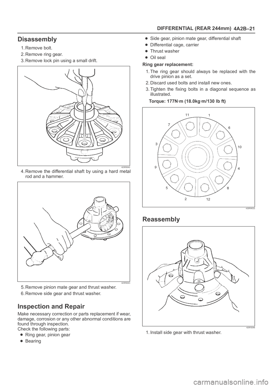
1. Remove bolt.
2. Remove ring gear.
3. Remove lock pin using a small drift.
425RS042
4. Remove the differential shaft by using a hard metal
rod and a hammer.
425RS043
5. Remove pinion mate gear and thrust washer.
6. Remove side gear and thrust washer.
Inspection and Repair
Make necessary correction or parts replacement if wear,
damage, corrosion or any other abnormal conditions are
found through inspection.
Check the following parts:
Ring gear, pinion gear
Bearing
Side gear, pinion mate gear, differential shaft
Differential cage, carrier
Thrust washer
Oil seal
Ring gear replacement:
1. The ring gear should always be replaced with the
drive pinion as a set.
2. Discard used bolts and install new ones.
3. Tighten the fixing bolts in a diagonal sequence as
illustrated.
Torque: 177Nꞏm (18.0kgꞏm/130 lb ft)
425RW033
Reassembly
425RS048
1. Install side gear with thrust washer.
Page 577 of 6000
DRIVE LINE CONTROL SYSTEM (TOD) 4B2–6
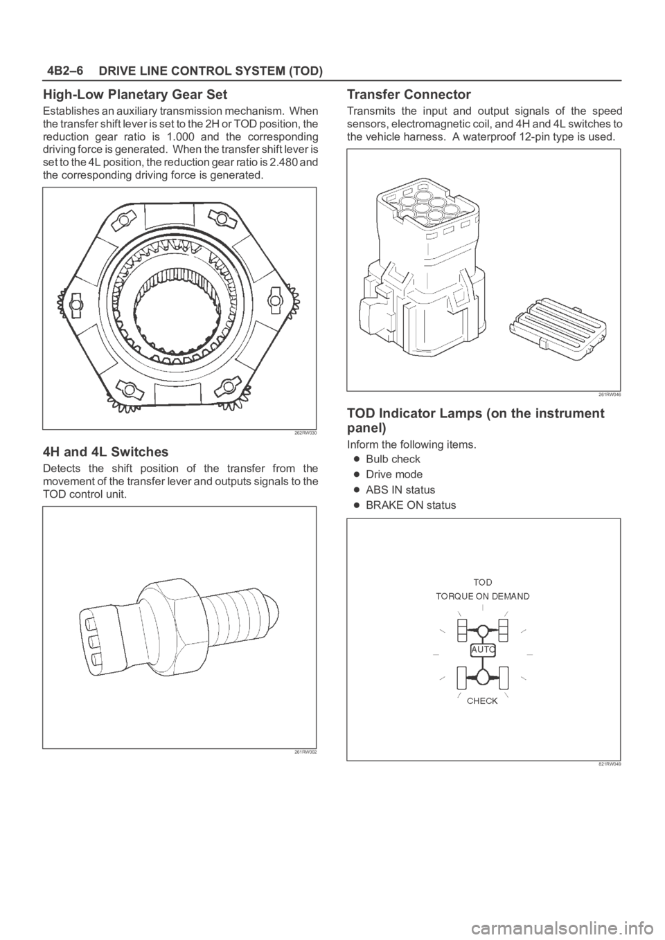
High-Low Planetary Gear Set
Establishes an auxiliary transmission mechanism. When
the transfer shift lever is set to the 2H or TOD position, the
reduction gear ratio is 1.000 and the corresponding
driving force is generated. When the transfer shift lever is
set to the 4L position, the reduction gear ratio is 2.480 and
the corresponding driving force is generated.
262RW030
4H and 4L Switches
Detects the shift position of the transfer from the
movement of the transfer lever and outputs signals to the
TOD control unit.
261RW002
Transfer Connector
Transmits the input and output signals of the speed
sensors, electromagnetic coil, and 4H and 4L switches to
the vehicle harness. A waterproof 12-pin type is used.
261RW046
TOD Indicator Lamps (on the instrument
panel)
Inform the following items.
Bulb check
Drive mode
ABS IN status
BRAKE ON status
821RW049
Page 601 of 6000
DRIVE LINE CONTROL SYSTEM (TOD) 4B2–30
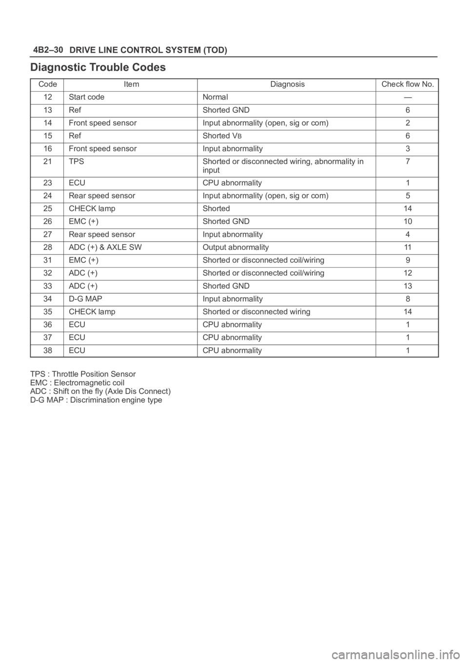
Diagnostic Trouble Codes
CodeItemDiagnosisCheck flow No.
12Start codeNormal—
13RefShorted GND6
14Front speed sensorInput abnormality (open, sig or com)2
15RefShorted VB6
16Front speed sensorInput abnormality3
21TPSShorted or disconnected wiring, abnormality in
input7
23ECUCPU abnormality1
24Rear speed sensorInput abnormality (open, sig or com)5
25CHECK lampShorted14
26EMC (+)Shorted GND10
27Rear speed sensorInput abnormality4
28ADC (+) & AXLE SWOutput abnormality11
31EMC (+)Shorted or disconnected coil/wiring9
32ADC (+)Shorted or disconnected coil/wiring12
33ADC (+)Shorted GND13
34D-G MAPInput abnormality8
35CHECK lampShorted or disconnected wiring14
36ECUCPU abnormality1
37ECUCPU abnormality1
38ECUCPU abnormality1
TPS : Throttle Position Sensor
EMC : Electromagnetic coil
ADC : Shift on the fly (Axle Dis Connect)
D-G MAP : Discrimination engine type
Page 617 of 6000

DRIVE LINE CONTROL SYSTEM (TOD) 4B2–46
Check flowTrouble codePhenomenonStandard
931The electromagnetic coil is broken.—
D04RW060
Page 618 of 6000
4B2–47 DRIVE LINE CONTROL SYSTEM (TOD)
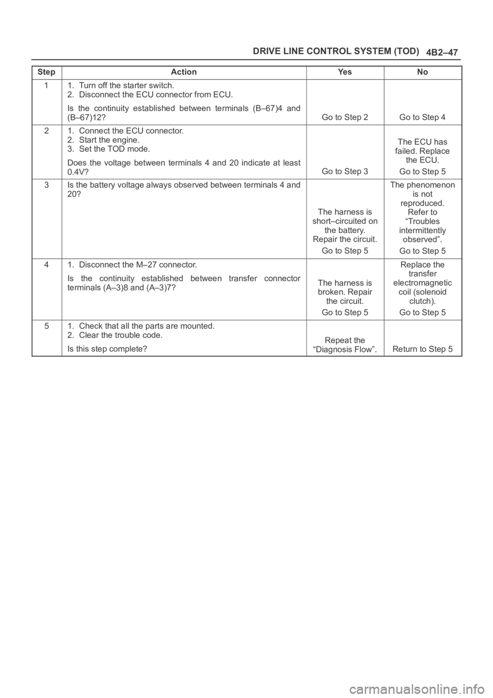
StepActionYe sNo
11. Turn off the starter switch.
2. Disconnect the ECU connector from ECU.
Is the continuity established between terminals (B–67)4 and
(B–67)12?
Go to Step 2Go to Step 4
21. Connect the ECU connector.
2. Start the engine.
3. Set the TOD mode.
Does the voltage between terminals 4 and 20 indicate at least
0.4V?
Go to Step 3
The ECU has
failed. Replace
the ECU.
Go to Step 5
3Is the battery voltage always observed between terminals 4 and
20?
The harness is
short–circuited on
the battery.
Repair the circuit.
Go to Step 5
The phenomenon
is not
reproduced.
Refer to
“Troubles
intermittently
observed”.
Go to Step 5
41. Disconnect the M–27 connector.
Is the continuity established between transfer connector
terminals (A–3)8 and (A–3)7?
The harness is
broken. Repair
the circuit.
Go to Step 5
Replace the
transfer
electromagnetic
coil (solenoid
clutch).
Go to Step 5
51. Check that all the parts are mounted.
2. Clear the trouble code.
Is this step complete?
Repeat the
“Diagnosis Flow”.
Return to Step 5
Page 619 of 6000
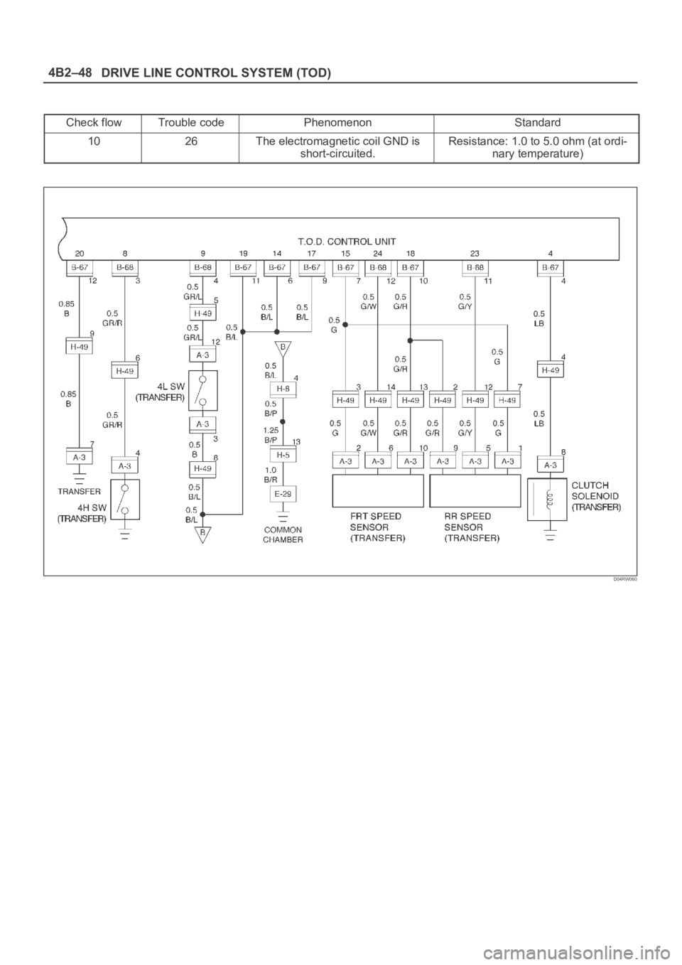
DRIVE LINE CONTROL SYSTEM (TOD) 4B2–48
Check flowTrouble codePhenomenonStandard
1026The electromagnetic coil GND is
short-circuited.Resistance: 1.0 to 5.0 ohm (at ordi-
nary temperature)
D04RW060
Page 620 of 6000
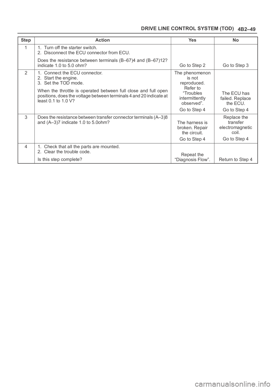
4B2–49 DRIVE LINE CONTROL SYSTEM (TOD)
StepActionYe sNo
11. Turn off the starter switch.
2. Disconnect the ECU connector from ECU.
Does the resistance between terminals (B–67)4 and (B–67)12?
indicate 1.0 to 5.0 ohm?
Go to Step 2Go to Step 3
21. Connect the ECU connector.
2. Start the engine.
3. Set the TOD mode.
When the throttle is operated between full close and full open
positions, does the voltage between terminals 4 and 20 indicate a t
least 0.1 to 1.0 V?The phenomenon
is not
reproduced.
Refer to
“Troubles
intermittently
observed”.
Go to Step 4
The ECU has
failed. Replace
the ECU.
Go to Step 4
3Does the resistance between transfer connector terminals (A–3)8
and (A–3)7 indicate 1.0 to 5.0ohm?
The harness is
broken. Repair
the circuit.
Go to Step 4
Replace the
transfer
electromagnetic
coil.
Go to Step 4
41. Check that all the parts are mounted.
2. Clear the trouble code.
Is this step complete?
Repeat the
“Diagnosis Flow”.
Return to Step 4
Page 626 of 6000
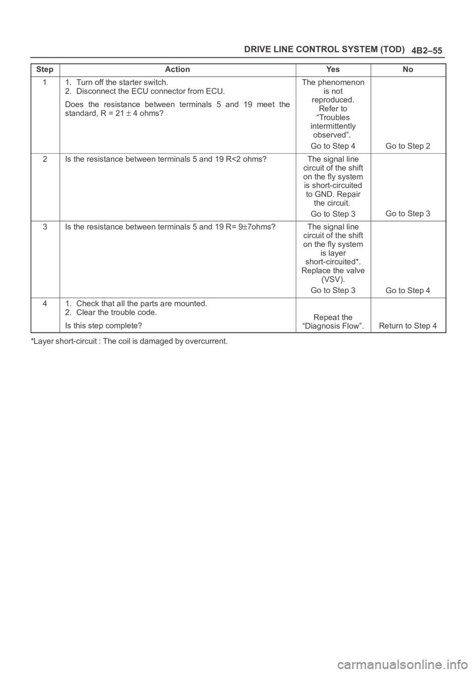
4B2–55 DRIVE LINE CONTROL SYSTEM (TOD)
StepActionYe sNo
11. Turn off the starter switch.
2. Disconnect the ECU connector from ECU.
Does the resistance between terminals 5 and 19 meet the
standard, R = 21
4 ohms?
The phenomenon
is not
reproduced.
Refer to
“Troubles
intermittently
observed”.
Go to Step 4
Go to Step 2
2Is the resistance between terminals 5 and 19 R<2 ohms?The signal line
circuit of the shift
on the fly system
is short-circuited
to GND. Repair
the circuit.
Go to Step 3
Go to Step 3
3Is the resistance between terminals 5 and 19 R= 97ohms?The signal line
circuit of the shift
on the fly system
is layer
short-circuited*.
Replace the valve
(VSV).
Go to Step 3
Go to Step 4
41. Check that all the parts are mounted.
2. Clear the trouble code.
Is this step complete?
Repeat the
“Diagnosis Flow”.
Return to Step 4
*Layer short-circuit : The coil is damaged by overcurrent.
Page 659 of 6000
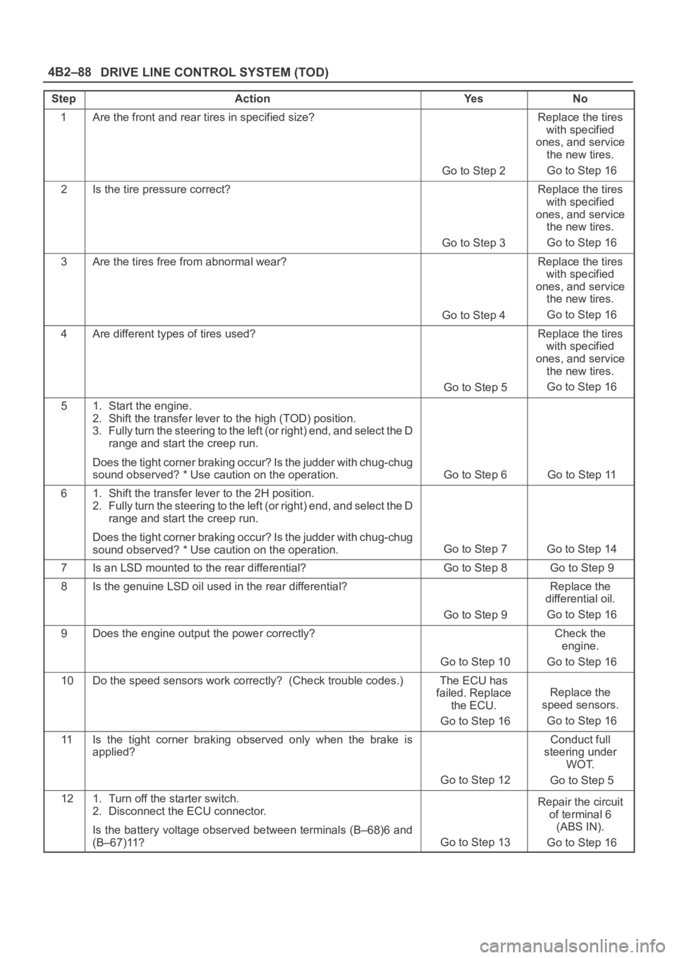
DRIVE LINE CONTROL SYSTEM (TOD) 4B2–88
StepActionYe sNo
1Are the front and rear tires in specified size?
Go to Step 2
Replace the tires
with specified
ones, and service
the new tires.
Go to Step 16
2Is the tire pressure correct?
Go to Step 3
Replace the tires
with specified
ones, and service
the new tires.
Go to Step 16
3Are the tires free from abnormal wear?
Go to Step 4
Replace the tires
with specified
ones, and service
the new tires.
Go to Step 16
4Are different types of tires used?
Go to Step 5
Replace the tires
with specified
ones, and service
the new tires.
Go to Step 16
51. Start the engine.
2. Shift the transfer lever to the high (TOD) position.
3. Fully turn the steering to the left (or right) end, and select the D
range and start the creep run.
Does the tight corner braking occur? Is the judder with chug-chug
sound observed? * Use caution on the operation.
Go to Step 6 Go to Step 11
61. Shift the transfer lever to the 2H position.
2. Fully turn the steering to the left (or right) end, and select the D
range and start the creep run.
Does the tight corner braking occur? Is the judder with chug-chug
sound observed? * Use caution on the operation.
Go to Step 7 Go to Step 14
7Is an LSD mounted to the rear differential? Go to Step 8 Go to Step 9
8Is the genuine LSD oil used in the rear differential?
Go to Step 9
Replace the
differential oil.
Go to Step 16
9Does the engine output the power correctly?
Go to Step 10
Check the
engine.
Go to Step 16
10Do the speed sensors work correctly? (Check trouble codes.)The ECU has
failed. Replace
the ECU.
Go to Step 16
Replace the
speed sensors.
Go to Step 16
11Is the tight corner braking observed only when the brake is
applied?
Go to Step 12
Conduct full
steering under
WOT.
Go to Step 5
121. Turn off the starter switch.
2. Disconnect the ECU connector.
Is the battery voltage observed between terminals (B–68)6 and
(B–67)11?
Go to Step 13
Repair the circuit
of terminal 6
(ABS IN).
Go to Step 16
Page 671 of 6000
4C–5 DRIVE SHAFT SYSTEM
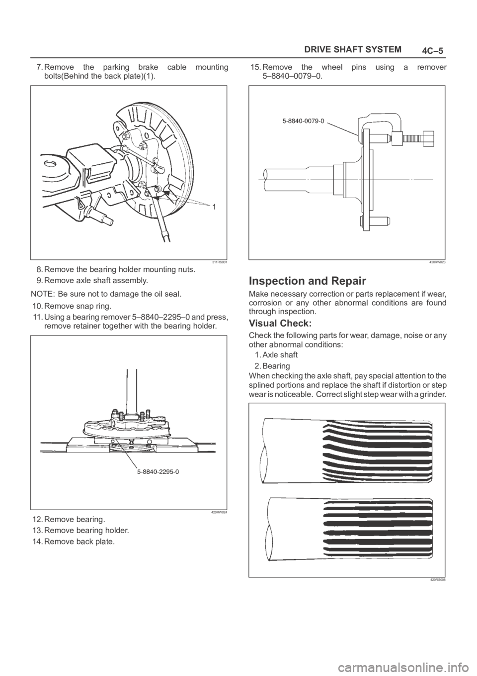
7.Remove the parking brake cable mounting
bolts(Behind the back plate)(1).
311RS001
8. Remove the bearing holder mounting nuts.
9. Remove axle shaft assembly.
NOTE: Be sure not to damage the oil seal.
10. Remove snap ring.
11. Using a bearing remover 5–8840–2295–0 and press,
remove retainer together with the bearing holder.
420RW024
12. Remove bearing.
13. Remove bearing holder.
14. Remove back plate.15. Remove the wheel pins using a remover
5–8840–0079–0.
420RW023
Inspection and Repair
Make necessary correction or parts replacement if wear,
corrosion or any other abnormal conditions are found
through inspection.
Visual Check:
Check the following parts for wear, damage, noise or any
other abnormal conditions:
1. Axle shaft
2. Bearing
When checking the axle shaft, pay special attention to the
splined portions and replace the shaft if distortion or step
wear is noticeable. Correct slight step wear with a grinder.
420RS008