OPEL FRONTERA 1998 Workshop Manual
Manufacturer: OPEL, Model Year: 1998, Model line: FRONTERA, Model: OPEL FRONTERA 1998Pages: 6000, PDF Size: 97 MB
Page 451 of 6000

DIFFERENTIAL (FRONT) 4A1–14
7. Record the pinion depth code on the head of the
drive pinion.
The number indicates a necessary change in the
pinion mounting distance. A plus number indi-
cates the need for a greater mounting distance
(which can be achieved by decreasing the shim
thickness). A minus number indicates the need
for a smaller mounting distance (which can be
achieved by increasing the shim thickness). If ex-
amination reveals pinion depth code “0”, the pin-
ion is “nominal”.
425RS023
Page 452 of 6000

4A1–15 DIFFERENTIAL (FRONT)
8. Select the shim using the chart;
Pinion marking+10+8+6+4+20–2–4–6–8–10
Dial indicator
reading
(Inches)mm
(Inches)mm
(Inches)mm
(Inches)mm
(Inches)mm
(Inches)mm
(Inches)mm
(Inches)mm
(Inches)mm
(Inches)mm
(Inches)mm
(Inches)
0.0812.18
(0.0858)
0.0822.18
(0.0858)2.20
(0.0866)
0.0832.18
(0.0858)2.20
(0.0866)2.23
(0.0882)
0.0842.18
(0.0858)2.20
(0.0866)2.24
(0.0882)2.26
(0.0890)
0.0852.18
(0.0858)2.20
(0.0866)2.24
(0.0882)2.26
(0.0890)2.28
(0.0898)
0.0862.18
(0.0858)2.20
(0.0866)2.24
(0.0882)2.26
(0.0890)2.28
(0.0898)2.32
(0.0914)
0.0872.18
(0.0858)2.20
(0.0866)2.24
(0.0882)2.26
(0.0890)2.28
(0.0898)2.32
(0.0914)2.34
(0.0921)
0.0882.18
(0.0858)2.20
(0.0866)2.24
(0.0882)2.26
(0.0890)2.28
(0.0898)2.32
(0.0914)2.34
(0.0921)2.36
(0.0929)
0.0892.18
(0.0858)2.20
(0.0866)2.24
(0.0882)2.26
(0.0890)2.28
(0.0898)2.32
(0.0914)2.34
(0.0921)2.36
(0.0929)2.38
(0.0937)
0.0902.18
(0.0858)2.20
(0.0866)2.24
(0.0882)2.26
(0.0890)2.28
(0.0898)2.32
(0.0914)2.34
(0.0921)2.36
(0.0929)2.38
(0.0937)2.42
(0.0953)
0.0912.18
(0.0858)2.20
(0.0866)2.24
(0.0882)2.26
(0.0890)2.28
(0.0898)2.32
(0.0914)2.34
(0.0921)2.36
(0.0929)2.38
(0.0937)2.42
(0.0953)2.44
(0.0961)
0.0922.20
(0.0866)2.24
(0.0882)2.26
(0.0890)2.28
(0.0898)2.32
(0.0914)2.34
(0.0921)2.36
(0.0929)2.38
(0.0937)2.42
(0.0953)2.44
(0.0961)2.46
(0.0969)
0.0932.24
(0.0882)2.26
(0.0890)2.28
(0.0898)2.32
(0.0914)2.34
(0.0921)2.36
(0.0929)2.38
(0.0937)2.42
(0.0953)2.44
(0.0961)2.46
(0.0969)2.48
(0.0977)
0.0942.26
(0.0890)2.28
(0.0898)2.32
(0.0914)2.34
(0.0921)2.36
(0.0929)2.38
(0.0937)2.42
(0.0953)2.44
(0.0961)2.46
(0.0969)2.48
(0.0977)2.52
(0.0992)
0.0952.28
(0.0898)2.32
(0.0914)2.34
(0.0921)2.36
(0.0929)2.38
(0.0937)2.42
(0.0953)2.44
(0.0961)2.46
(0.0969)2.48
(0.0977)2.52
(0.0992)2.54
(0.1000)
0.0962.32
(0.0914)2.34
(0.0921)2.36
(0.0929)2.38
(0.0937)2.42
(0.0953)2.44
(0.0961)2.46
(0.0969)2.48
(0.0977)2.52
(0.0992)2.54
(0.1000)2.56
(0.1008)
0.0972.34
(0.0921)2.36
(0.0929)2.38
(0.0937)2.42
(0.0953)2.44
(0.0961)2.46
(0.0969)2.48
(0.0977)2.52
(0.0992)2.54
(0.1000)2.56
(0.1008)
0.0982.36
(0.0929)2.38
(0.0937)2.42
(0.0953)2.44
(0.0961)2.46
(0.0969)2.48
(0.0977)2.52
(0.0992)2.54
(0.1000)2.56
(0.1008)
0.0992.38
(0.0937)2.42
(0.0953)2.44
(0.0961)2.46
(0.0969)2.48
(0.0977)2.52
(0.0992)2.54
(0.1000)2.56
(0.1008)
02.42
(0.0953)2.44
(0.0961)2.46
(0.0969)2.48
(0.0977)2.52
(0.0992)2.54
(0.1000)2.56
(0.1008)
0.0012.44
(0.0961)2.46
(0.0969)2.48
(0.0977)2.52
(0.0992)2.54
(0.1000)2.56
(0.1008)
0.0022.46
(0.0969)2.48
(0.0977)2.52
(0.0992)2.54
(0.1000)2.56
(0.1008)
0.0032.48
(0.0977)2.52
(0.0992)2.54
(0.1000)2.56
(0.1008)
0.0042.52
(0.0992)2.54
(0.1000)2.56
(0.1008)
0.0052.54
(0.1000)2.56
(0.1008)
0.0062.56
(0.1008)
NOTE: When ordering shims, find the part number in the
parts catalog by using the thickness of shims listed in the
above table.4. Place the shim on the drive pinion, with the chamfered
side turned towards the pinion head then install the
inner bearing onto the pinion using an installer
9–8522–1165–0 and a press.
Page 453 of 6000
DIFFERENTIAL (FRONT) 4A1–16
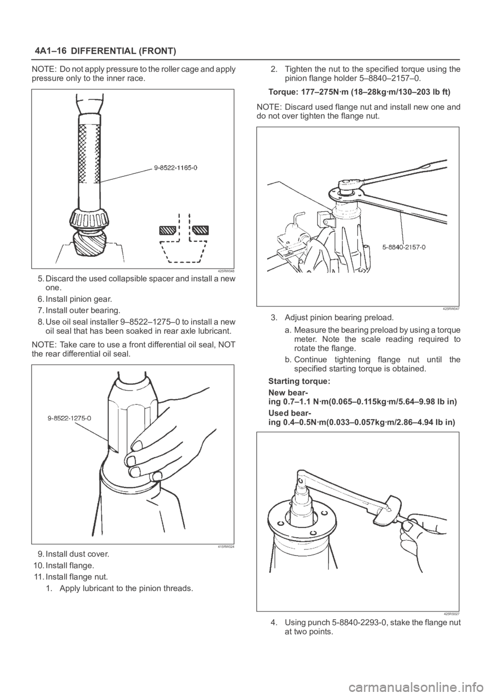
NOTE: Do not apply pressure to the roller cage and apply
pressure only to the inner race.
425RW048
5. Discard the used collapsible spacer and install a new
one.
6. Install pinion gear.
7. Install outer bearing.
8. Use oil seal installer 9–8522–1275–0 to install a new
oil seal that has been soaked in rear axle lubricant.
NOTE: Take care to use a front differential oil seal, NOT
the rear differential oil seal.
415RW024
9. Install dust cover.
10. Install flange.
11. Install flange nut.
1. Apply lubricant to the pinion threads.2. Tighten the nut to the specified torque using the
pinion flange holder 5–8840–2157–0.
Torque: 177–275Nꞏm (18–28kgꞏm/130–203 lb ft)
NOTE: Discard used flange nut and install new one and
do not over tighten the flange nut.
425RW047
3. Adjust pinion bearing preload.
a. Measure the bearing preload by using a torque
meter. Note the scale reading required to
rotate the flange.
b. Continue tightening flange nut until the
specified starting torque is obtained.
Starting torque:
New bear-
ing 0.7–1.1 Nꞏm(0.065–0.115kgꞏm/5.64–9.98 lb in)
Used bear-
ing 0.4–0.5Nꞏm(0.033–0.057kgꞏm/2.86–4.94 Ib in)
425RS027
4. Using punch 5-8840-2293-0, stake the flange nut
at two points.
Page 454 of 6000

4A1–17 DIFFERENTIAL (FRONT)
NOTE: When staking, be sure to turn the nut to insure
that there is no change in bearing preload. Make sure of
preload again as instructed in 3).
415RW019
Legend
(1) 1.3mm or less
12. Install adjust shim.
1. Attach the side bearing to the differential
assembly without shims. Support the opposite
side using a pilot to prevent bearing damage.
425RS029
Legend
(1) Drive handle:5–8840–0007–0
(2) Installer:9–8522–1164–0
(3) Pilot:9–8521–1743–0
2. Insert the differential cage assembly with bearing
outer races into the side bearing bores of the
carrier.
425RS030
3. Using two sets of feeler gauges, insert a feeler
stock of sufficient thickness between each
bearing outer race and the carrier to remove all
end play. Make certain the feeler stock is pushed
to the bottom of the bearing bores.
Mount the dial indicator 5–8840–0126–0 on the
carrier so that the indicator stem is at right angles
to a tooth on the ring gear.
425RW049
Page 455 of 6000
DIFFERENTIAL (FRONT) 4A1–18
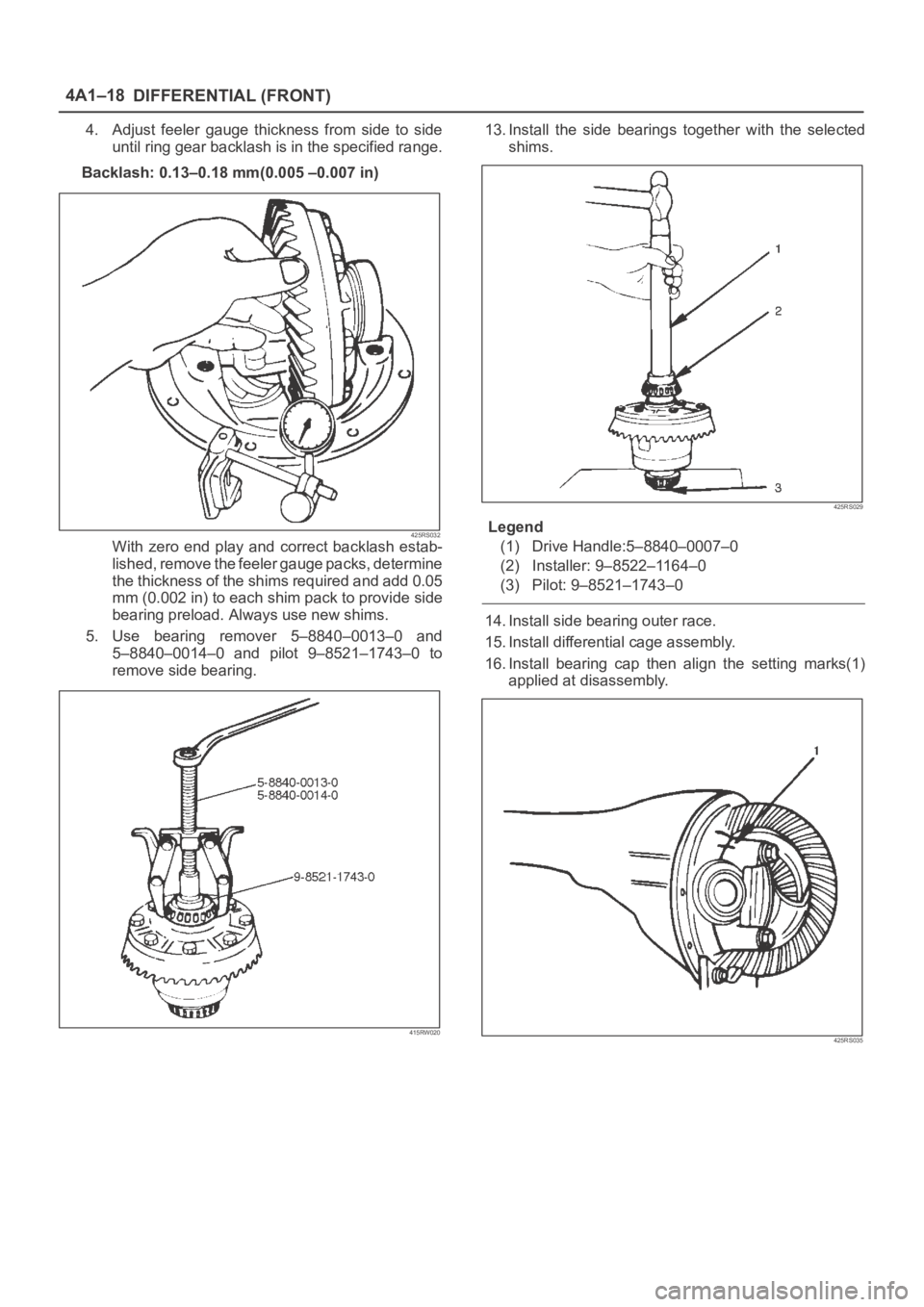
4. Adjust feeler gauge thickness from side to side
until ring gear backlash is in the specified range.
Backlash: 0.13–0.18 mm(0.005 –0.007 in)
425RS032With zero end play and correct backlash estab-
lished, remove the feeler gauge packs, determine
the thickness of the shims required and add 0.05
mm (0.002 in) to each shim pack to provide side
bearing preload. Always use new shims.
5. Use bearing remover 5–8840–0013–0 and
5–8840–0014–0 and pilot 9–8521–1743–0 to
remove side bearing.
415RW020
13. Install the side bearings together with the selected
shims.
425RS029
Legend
(1) Drive Handle:5–8840–0007–0
(2) Installer: 9–8522–1164–0
(3) Pilot: 9–8521–1743–0
14. Install side bearing outer race.
15. Install differential cage assembly.
16. Install bearing cap then align the setting marks(1)
applied at disassembly.
425RS035
Page 456 of 6000
4A1–19 DIFFERENTIAL (FRONT)
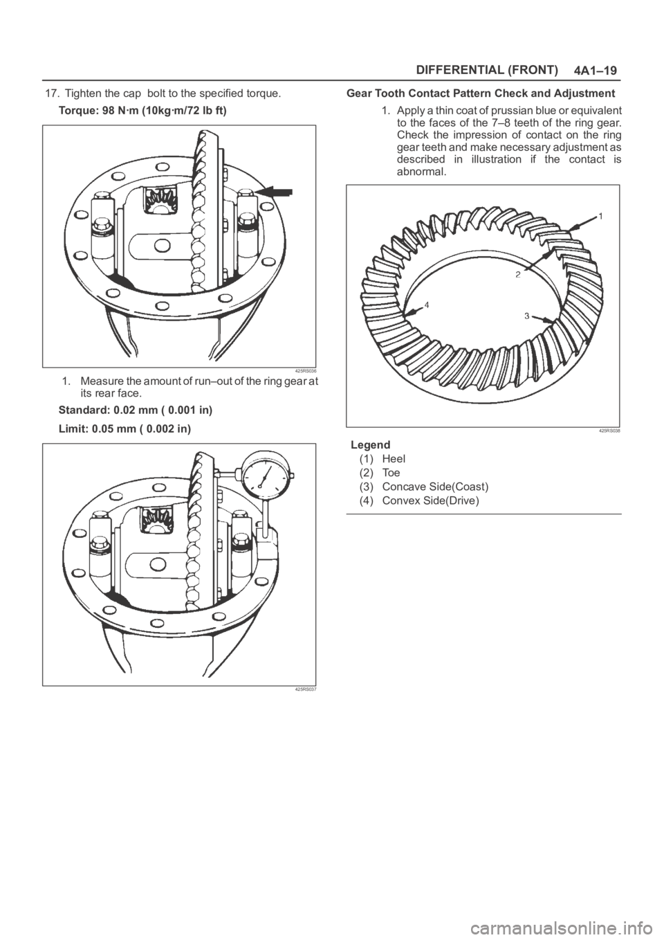
17. Tighten the cap bolt to the specified torque.
To r q u e : 9 8 N ꞏm ( 1 0 k g ꞏm / 7 2 l b f t )
425RS036
1. Measure the amount of run–out of the ring gear at
its rear face.
Standard: 0.02 mm ( 0.001 in)
Limit: 0.05 mm ( 0.002 in)
425RS037
Gear Tooth Contact Pattern Check and Adjustment
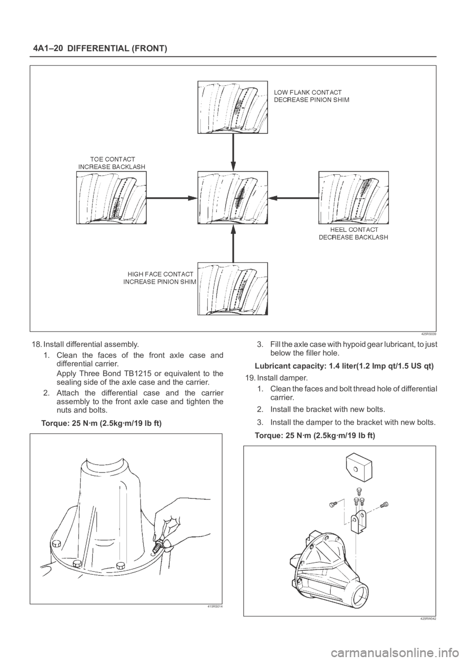
1. Apply a thin coat of prussian blue or equivalent
to the faces of the 7–8 teeth of the ring gear.
Check the impression of contact on the ring
gear teeth and make necessary adjustment as
described in illustration if the contact is
abnormal.
425RS038
Legend
(1) Heel
(2) Toe
(3) Concave Side(Coast)
(4) Convex Side(Drive)
Page 457 of 6000
DIFFERENTIAL (FRONT) 4A1–20
425RS039
18. Install differential assembly.
1. Clean the faces of the front axle case and
differential carrier.
Apply Three Bond TB1215 or equivalent to the
sealing side of the axle case and the carrier.
2. Attach the differential case and the carrier
assembly to the front axle case and tighten the
nuts and bolts.
To r q u e : 2 5 N ꞏm ( 2 . 5 k g ꞏm / 1 9 l b f t )
415RS014
3. Fill the axle case with hypoid gear lubricant, to just
below the filler hole.
Lubricant capacity: 1.4 liter(1.2 Imp qt/1.5 US qt)
19. Install damper.
1. Clean the faces and bolt thread hole of differential
carrier.
2. Install the bracket with new bolts.
3. Install the damper to the bracket with new bolts.
Torque: 25 Nꞏm (2.5kgꞏm/19 lb ft)
425RW042
Page 458 of 6000

4A1–21 DIFFERENTIAL (FRONT)
Differential Cage Assembly
Disassembled View
415RS015
Legend
(1) Pinion Gear
(2) Thrust Washer
(3) Side Gear
(4) Cross Pin(5) Ring Gear
(6) Bolt
(7) Differential Cage
(8) Lock Pin
Disassembly
1. Remove bolt.
2. Remove ring gear.
3. Remove lock pin, break staking on the lock pin, using
a 5 mm (0.20 in) diameter drill.
425RS042
Page 459 of 6000
DIFFERENTIAL (FRONT) 4A1–22
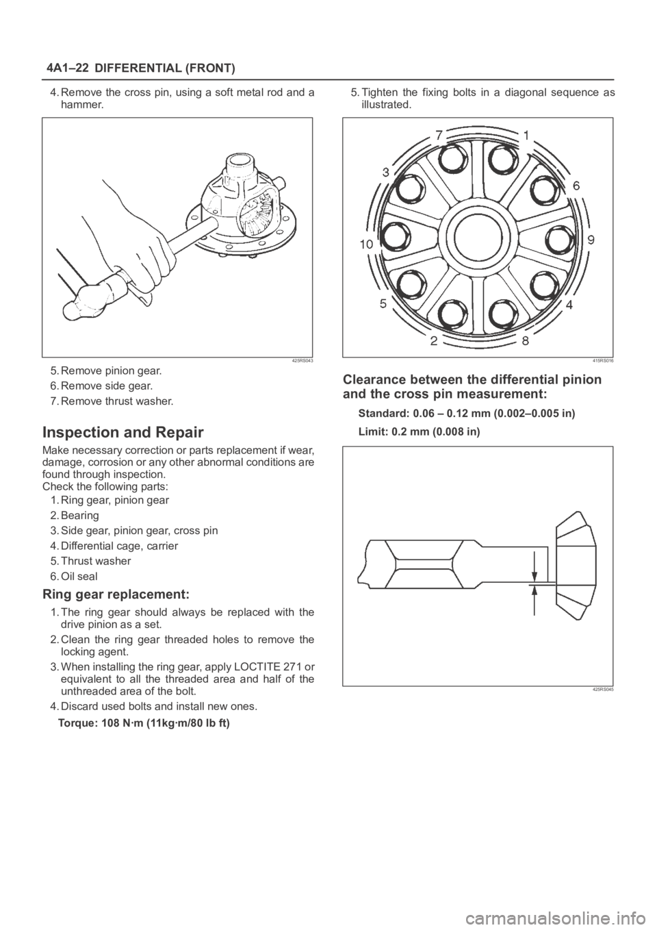
4. Remove the cross pin, using a soft metal rod and a
hammer.
425RS043
5. Remove pinion gear.
6. Remove side gear.
7. Remove thrust washer.
Inspection and Repair
Make necessary correction or parts replacement if wear,
damage, corrosion or any other abnormal conditions are
found through inspection.
Check the following parts:
1. Ring gear, pinion gear
2. Bearing
3. Side gear, pinion gear, cross pin
4. Differential cage, carrier
5. Thrust washer
6. Oil seal
Ring gear replacement:
1. The ring gear should always be replaced with the
drive pinion as a set.
2. Clean the ring gear threaded holes to remove the
locking agent.
3. When installing the ring gear, apply LOCTITE 271 or
equivalent to all the threaded area and half of the
unthreaded area of the bolt.
4. Discard used bolts and install new ones.
Torque: 108 Nꞏm (11kgꞏm/80 lb ft)5. Tighten the fixing bolts in a diagonal sequence as
illustrated.
415RS016
Clearance between the differential pinion
and the cross pin measurement:
Standard: 0.06 – 0.12 mm (0.002–0.005 in)
Limit: 0.2 mm (0.008 in)
425RS045
Page 460 of 6000
4A1–23 DIFFERENTIAL (FRONT)
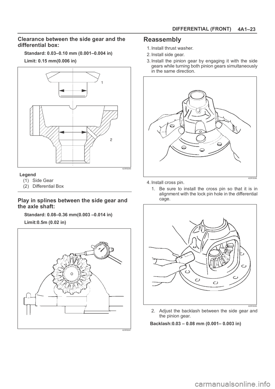
Clearance between the side gear and the
differential box:
Standard: 0.03–0.10 mm (0.001–0.004 in)
Limit: 0.15 mm(0.006 in)
425RS046
Legend
(1) Side Gear
(2) Differential Box
Play in splines between the side gear and
the axle shaft:
Standard: 0.08–0.36 mm(0.003 –0.014 in)
Limit:0.5m (0.02 in)
425RS047
Reassembly
1. Install thrust washer.
2. Install side gear.
3. Install the pinion gear by engaging it with the side
gears while turning both pinion gears simultaneously
in the same direction.
425RS048
4. Install cross pin.
1. Be sure to install the cross pin so that it is in
alignment with the lock pin hole in the differential
cage.
425RS049
2. Adjust the backlash between the side gear and
the pinion gear.
Backlash:0.03 – 0.08 mm (0.001– 0.003 in)