ignition OPEL FRONTERA 1998 Workshop Manual
[x] Cancel search | Manufacturer: OPEL, Model Year: 1998, Model line: FRONTERA, Model: OPEL FRONTERA 1998Pages: 6000, PDF Size: 97 MB
Page 4510 of 6000
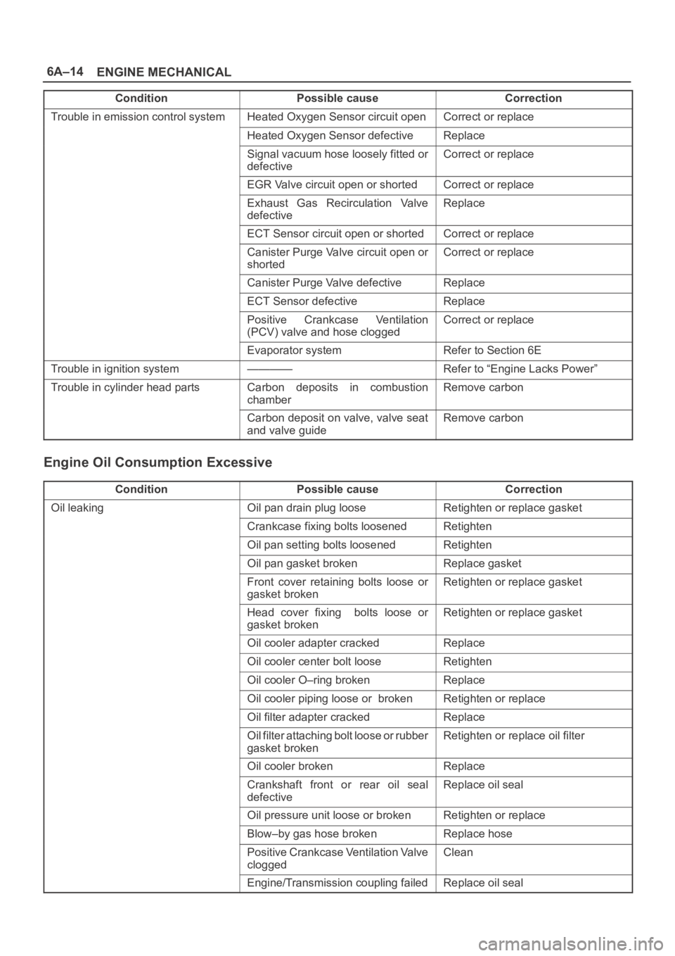
6A–14
ENGINE MECHANICAL
Condition CorrectionPossible cause
Trouble in emission control systemHeated Oxygen Sensor circuit openCorrect or replace
Heated Oxygen Sensor defectiveReplace
Signal vacuum hose loosely fitted or
defectiveCorrect or replace
EGR Valve circuit open or shortedCorrect or replace
Exhaust Gas Recirculation Valve
defectiveReplace
ECT Sensor circuit open or shortedCorrect or replace
Canister Purge Valve circuit open or
shortedCorrect or replace
Canister Purge Valve defectiveReplace
ECT Sensor defectiveReplace
Positive Crankcase Ventilation
(PCV) valve and hose cloggedCorrect or replace
Evaporator systemRefer to Section 6E
Trouble in ignition system————Refer to “Engine Lacks Power”
Trouble in cylinder head partsCarbon deposits in combustion
chamberRemove carbon
Carbon deposit on valve, valve seat
and valve guideRemove carbon
Engine Oil Consumption Excessive
ConditionPossible causeCorrection
Oil leakingOil pan drain plug looseRetighten or replace gasket
Crankcase fixing bolts loosenedRetighten
Oil pan setting bolts loosenedRetighten
Oil pan gasket brokenReplace gasket
Front cover retaining bolts loose or
gasket brokenRetighten or replace gasket
Head cover fixing bolts loose or
gasket brokenRetighten or replace gasket
Oil cooler adapter crackedReplace
Oil cooler center bolt looseRetighten
Oil cooler O–ring brokenReplace
Oil cooler piping loose or brokenRetighten or replace
Oil filter adapter crackedReplace
Oil filter attaching bolt loose or rubber
gasket brokenRetighten or replace oil filter
Oil cooler brokenReplace
Crankshaft front or rear oil seal
defectiveReplace oil seal
Oil pressure unit loose or brokenRetighten or replace
Blow–by gas hose brokenReplace hose
Positive Crankcase Ventilation Valve
cloggedClean
Engine/Transmission coupling failedReplace oil seal
Page 4511 of 6000
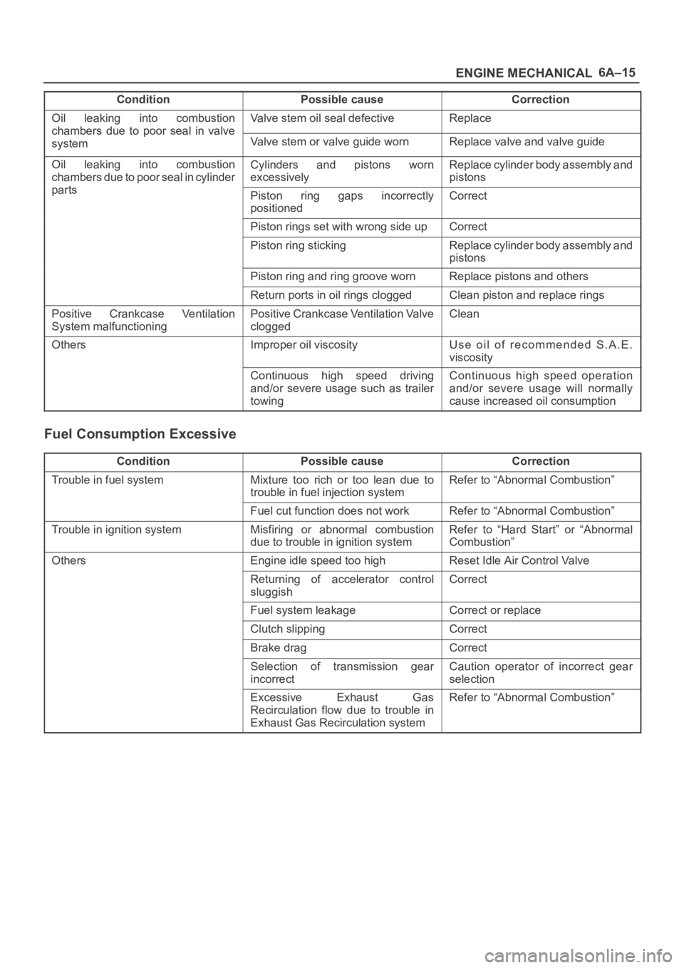
6A–15
ENGINE MECHANICAL
Condition CorrectionPossible cause
Oil leaking into combustion
chambers due topoor seal in valve
Valve stem oil seal defectiveReplace
chambers due to oor seal in valve
systemValve stem or valve guide wornReplace valve and valve guide
Oil leaking into combustion
chambers due to poor seal in cylinder
t
Cylinders and pistons worn
excessivelyReplace cylinder body assembly and
pistons
partsPiston ring gaps incorrectly
positionedCorrect
Piston rings set with wrong side upCorrect
Piston ring stickingReplace cylinder body assembly and
pistons
Piston ring and ring groove wornReplace pistons and others
Return ports in oil rings cloggedClean piston and replace rings
Positive Crankcase Ventilation
System malfunctioningPositive Crankcase Ventilation Valve
cloggedClean
OthersImproper oil viscosityUse oil of recommended S.A.E.
viscosity
Continuous high speed driving
and/or severe usage such as trailer
towingContinuous high speed operation
and/or severe usage will normally
cause increased oil consumption
Fuel Consumption Excessive
ConditionPossible causeCorrection
Trouble in fuel systemMixture too rich or too lean due to
trouble in fuel injection systemRefer to “Abnormal Combustion”
Fuel cut function does not workRefer to “Abnormal Combustion”
Trouble in ignition systemMisfiring or abnormal combustion
due to trouble in ignition systemRefer to “Hard Start” or “Abnormal
Combustion”
OthersEngine idle speed too highReset Idle Air Control Valve
Returning of accelerator control
sluggishCorrect
Fuel system leakageCorrect or replace
Clutch slippingCorrect
Brake dragCorrect
Selection of transmission gear
incorrectCaution operator of incorrect gear
selection
Excessive Exhaust Gas
Recirculation flow due to trouble in
Exhaust Gas Recirculation systemRefer to “Abnormal Combustion”
Page 4514 of 6000
6A–18
ENGINE MECHANICAL
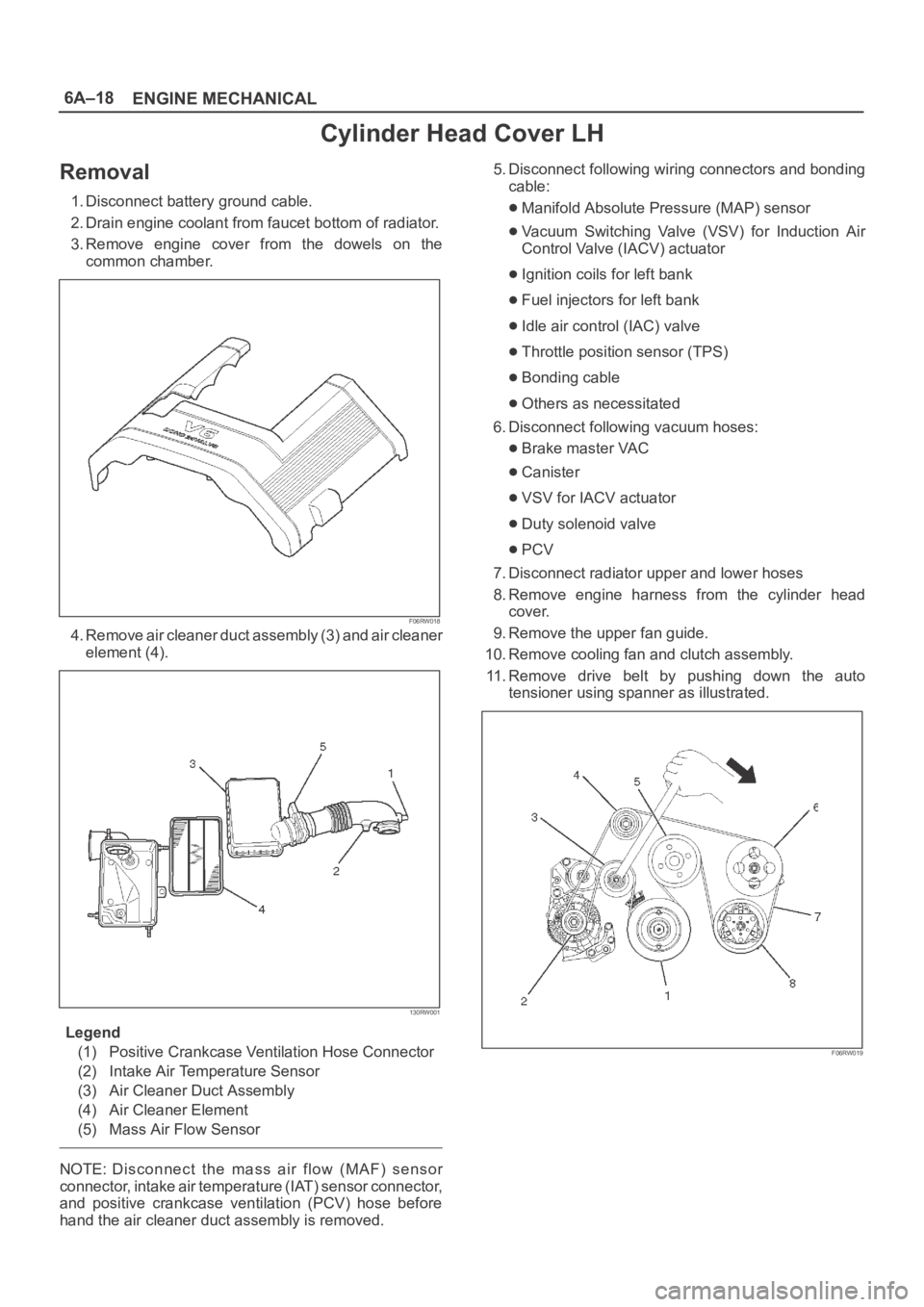
Cylinder Head Cover LH
Removal
1. Disconnect battery ground cable.
2. Drain engine coolant from faucet bottom of radiator.
3. Remove engine cover from the dowels on the
common chamber.
F06RW018
4. Remove air cleaner duct assembly (3) and air cleaner
element (4).
130RW001
Legend
(1) Positive Crankcase Ventilation Hose Connector
(2) Intake Air Temperature Sensor
(3) Air Cleaner Duct Assembly
(4) Air Cleaner Element
(5) Mass Air Flow Sensor
NOTE: Disconnect the mass air flow (MAF) sensor
connector, intake air temperature (IAT) sensor connector,
and positive crankcase ventilation (PCV) hose before
hand the air cleaner duct assembly is removed.5. Disconnect following wiring connectors and bonding
cable:
Manifold Absolute Pressure (MAP) sensor
Vacuum Switching Valve (VSV) for Induction Air
Control Valve (IACV) actuator
Ignition coils for left bank
Fuel injectors for left bank
Idle air control (IAC) valve
Throttle position sensor (TPS)
Bonding cable
Others as necessitated
6. Disconnect following vacuum hoses:
Brake master VAC
Canister
VSV for IACV actuator
Duty solenoid valve
PCV
7. Disconnect radiator upper and lower hoses
8. Remove engine harness from the cylinder head
cover.
9. Remove the upper fan guide.
10. Remove cooling fan and clutch assembly.
11. Remove drive belt by pushing down the auto
tensioner using spanner as illustrated.
F06RW019
Page 4515 of 6000
6A–19
ENGINE MECHANICAL
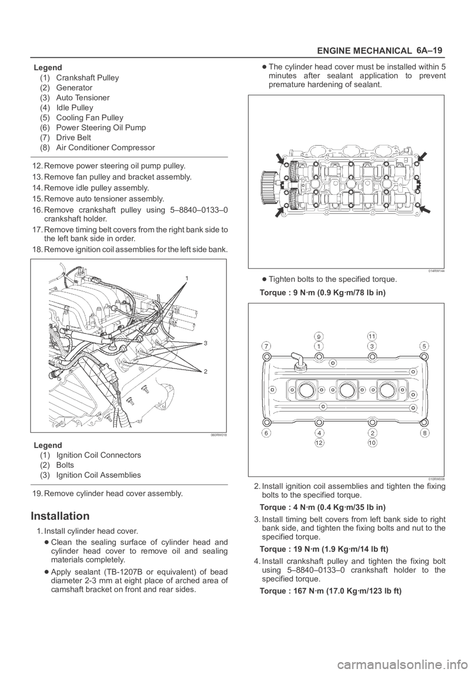
Legend
(1) Crankshaft Pulley
(2) Generator
(3) Auto Tensioner
(4) Idle Pulley
(5) Cooling Fan Pulley
(6) Power Steering Oil Pump
(7) Drive Belt
(8) Air Conditioner Compressor
12. Remove power steering oil pump pulley.
13. Remove fan pulley and bracket assembly.
14. Remove idle pulley assembly.
15. Remove auto tensioner assembly.
16. Remove crankshaft pulley using 5–8840–0133–0
crankshaft holder.
17. Remove timing belt covers from the right bank side to
the left bank side in order.
18. Remove ignition coil assemblies for the left side bank.
060RW018
Legend
(1) Ignition Coil Connectors
(2) Bolts
(3) Ignition Coil Assemblies
19. Remove cylinder head cover assembly.
Installation
1. Install cylinder head cover.
Clean the sealing surface of cylinder head and
cylinder head cover to remove oil and sealing
materials completely.
Apply sealant (TB-1207B or equivalent) of bead
diameter 2-3 mm at eight place of arched area of
camshaft bracket on front and rear sides.
The cylinder head cover must be installed within 5
minutes after sealant application to prevent
premature hardening of sealant.
014RW144
Tighten bolts to the specified torque.
Torque : 9 Nꞏm (0.9 Kgꞏm/78 lb in)
010RW008
2. Install ignition coil assemblies and tighten the fixing
bolts to the specified torque.
Torque : 4 Nꞏm (0.4 Kgꞏm/35 lb in)
3. Install timing belt covers from left bank side to right
bank side, and tighten the fixing bolts and nut to the
specified torque.
Torque : 19 Nꞏm (1.9 Kgꞏm/14 lb ft)
4. Install crankshaft pulley and tighten the fixing bolt
using 5–8840–0133–0 crankshaft holder to the
specified torque.
Torque : 167 Nꞏm (17.0 Kgꞏm/123 lb ft)
Page 4517 of 6000
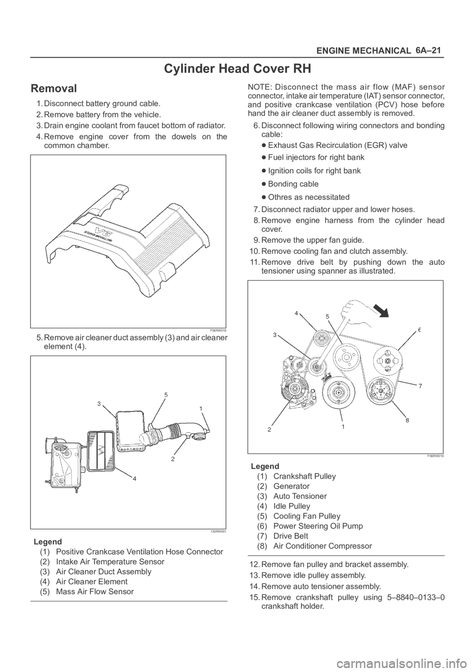
6A–21
ENGINE MECHANICAL
Cylinder Head Cover RH
Removal
1. Disconnect battery ground cable.
2. Remove battery from the vehicle.
3. Drain engine coolant from faucet bottom of radiator.
4. Remove engine cover from the dowels on the
common chamber.
F06RW018
5. Remove air cleaner duct assembly (3) and air cleaner
element (4).
130RW001
Legend
(1) Positive Crankcase Ventilation Hose Connector
(2) Intake Air Temperature Sensor
(3) Air Cleaner Duct Assembly
(4) Air Cleaner Element
(5) Mass Air Flow Sensor
NOTE: Disconnect the mass air flow (MAF) sensor
connector, intake air temperature (IAT) sensor connector,
and positive crankcase ventilation (PCV) hose before
hand the air cleaner duct assembly is removed.
6. Disconnect following wiring connectors and bonding
cable:
Exhaust Gas Recirculation (EGR) valve
Fuel injectors for right bank
Ignition coils for right bank
Bonding cable
Othres as necessitated
7. Disconnect radiator upper and lower hoses.
8. Remove engine harness from the cylinder head
cover.
9. Remove the upper fan guide.
10. Remove cooling fan and clutch assembly.
11. Remove drive belt by pushing down the auto
tensioner using spanner as illustrated.
F06RW019
Legend
(1) Crankshaft Pulley
(2) Generator
(3) Auto Tensioner
(4) Idle Pulley
(5) Cooling Fan Pulley
(6) Power Steering Oil Pump
(7) Drive Belt
(8) Air Conditioner Compressor
12. Remove fan pulley and bracket assembly.
13. Remove idle pulley assembly.
14. Remove auto tensioner assembly.
15. Remove crankshaft pulley using 5–8840–0133–0
crankshaft holder.
Page 4518 of 6000
6A–22
ENGINE MECHANICAL
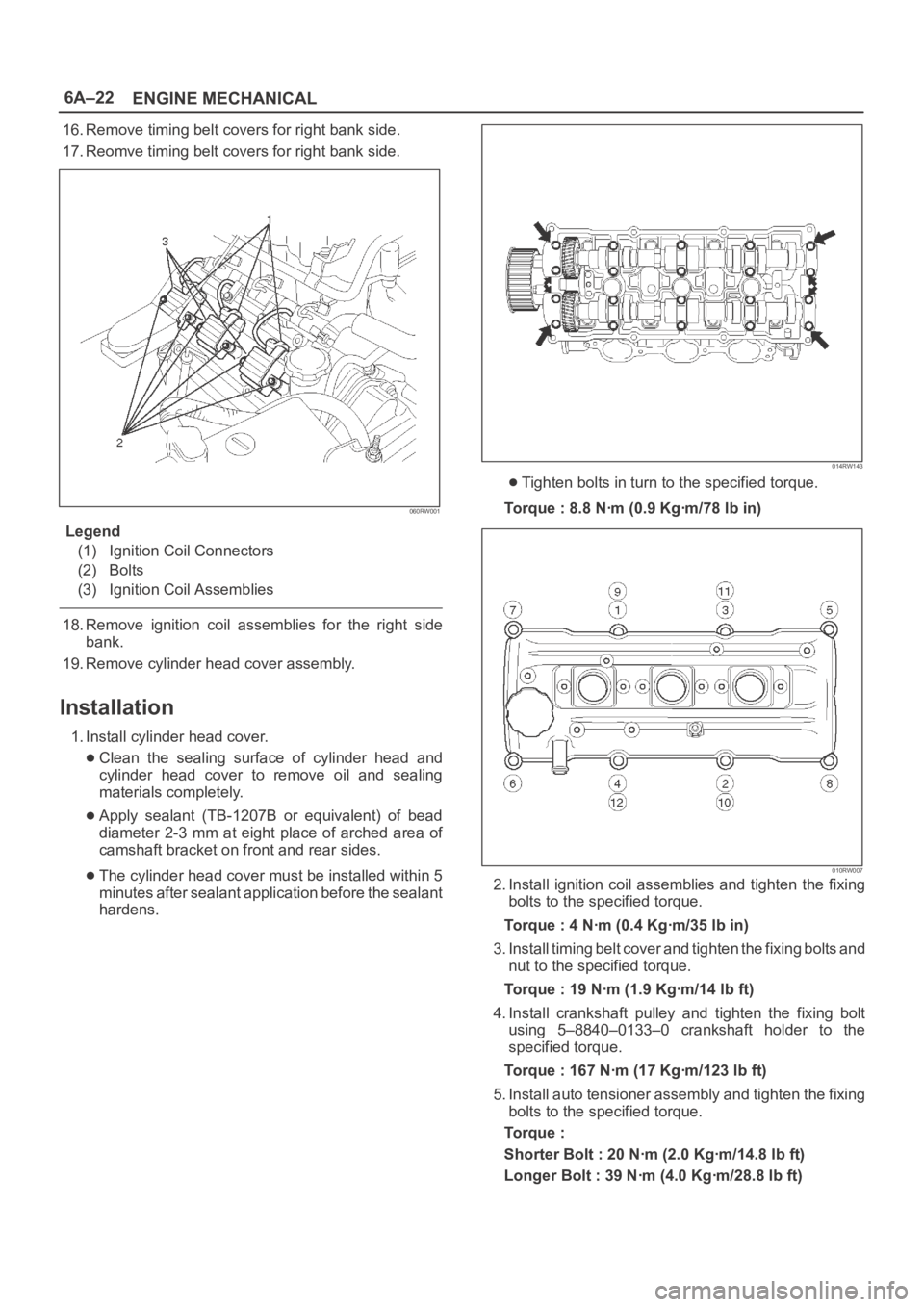
16. Remove timing belt covers for right bank side.
17. Reomve timing belt covers for right bank side.
060RW001
Legend
(1) Ignition Coil Connectors
(2) Bolts
(3) Ignition Coil Assemblies
18. Remove ignition coil assemblies for the right side
bank.
19. Remove cylinder head cover assembly.
Installation
1. Install cylinder head cover.
Clean the sealing surface of cylinder head and
cylinder head cover to remove oil and sealing
materials completely.
Apply sealant (TB-1207B or equivalent) of bead
diameter 2-3 mm at eight place of arched area of
camshaft bracket on front and rear sides.
The cylinder head cover must be installed within 5
minutes after sealant application before the sealant
hardens.
014RW143
Tighten bolts in turn to the specified torque.
Torque : 8.8 Nꞏm (0.9 Kgꞏm/78 lb in)
010RW007
2. Install ignition coil assemblies and tighten the fixing
bolts to the specified torque.
Torque : 4 Nꞏm (0.4 Kgꞏm/35 lb in)
3. Install timing belt cover and tighten the fixing bolts and
nut to the specified torque.
Torque : 19 Nꞏm (1.9 Kgꞏm/14 lb ft)
4. Install crankshaft pulley and tighten the fixing bolt
using 5–8840–0133–0 crankshaft holder to the
specified torque.
Torque : 167 Nꞏm (17 Kgꞏm/123 lb ft)
5. Install auto tensioner assembly and tighten the fixing
bolts to the specified torque.
Torque :
Shorter Bolt : 20 Nꞏm (2.0 Kgꞏm/14.8 lb ft)
Longer Bolt : 39 Nꞏm (4.0 Kgꞏm/28.8 lb ft)
Page 4586 of 6000
6A–90
ENGINE MECHANICAL
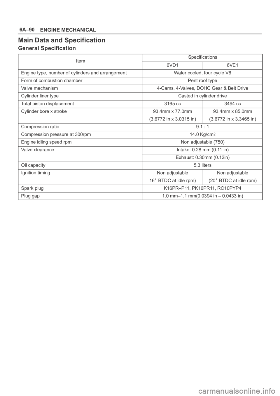
Main Data and Specification
General Specification
ItemSpecificationsItem6VD16VE1
Engine type, number of cylinders and arrangementWater cooled, four cycle V6
Form of combustion chamberPent roof type
Valve mechanism4-Cams, 4-Valves, DOHC Gear & Belt Drive
Cylinder liner typeCasted in cylinder drive
Total piston displacement3165 cc3494 cc
Cylinder bore x stroke93.4mm x 77.0mm93.4mm x 85.0mm
(3.6772 in x 3.0315 in)(3.6772 in x 3.3465 in)
Compression ratio9.1 : 1
Compression pressure at 300rpm14.0 Kg/cm
Engine idling speed rpmNon adjustable (750)
Valve clearanceIntake: 0.28 mm (0.11 in)
Exhaust: 0.30mm (0.12in)
Oil capacity5.3 liters
Ignition timingNon adjustableNon adjustable
16 BTDC at idle rpm)(20 BTDC at idle rpm)
Spark plugK16PR–P11, PK16PR11, RC10PYP4
Plug gap1.0 mm–1.1 mm(0.0394 in – 0.0433 in)
Page 4587 of 6000
6A–91
ENGINE MECHANICAL
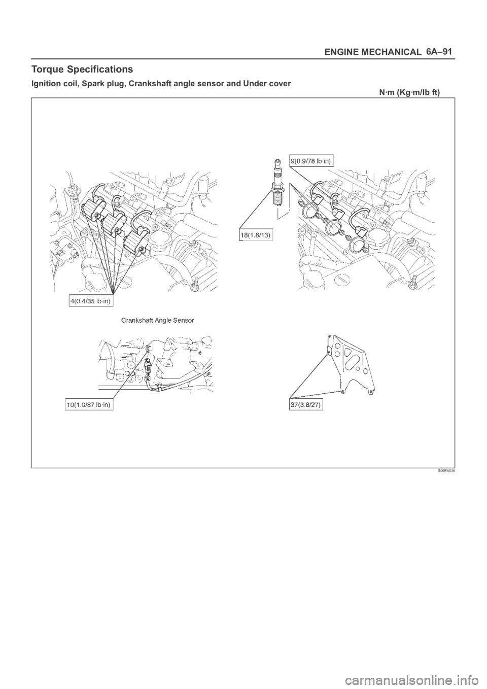
Torque Specifications
Ignition coil, Spark plug, Crankshaft angle sensor and Under cover
Nꞏm (Kgꞏm/Ib ft)
E06RW038
Page 4614 of 6000
6C–7
ENGINE FUEL
Fuel Pump Relay
General Description
In order to control the FP operation, the FP relay is
provided. When the starter switch is turned to “ON”
position, the FP relay operates the FP for 2 seconds.When it is turned to “START” position, the Power Train
Control Module (PCM) receives the reference pulse from
the Ignition Control Module and it operates the relay,
again causing the FP to feed fuel.
Fuel Tank
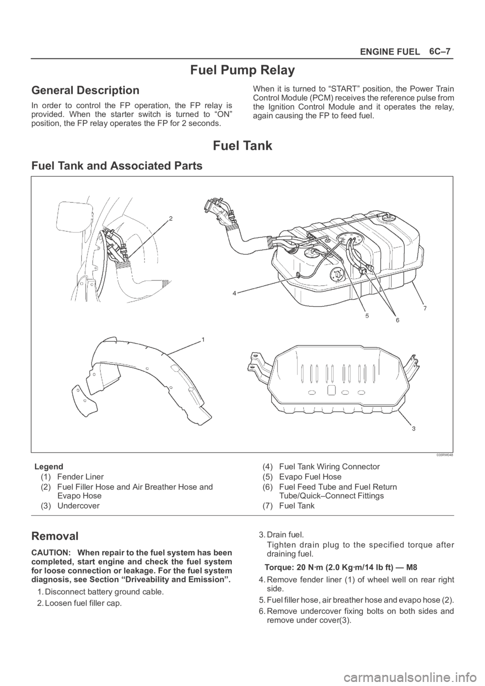
Fuel Tank and Associated Parts
035RW048
Legend
(1) Fender Liner
(2) Fuel Filler Hose and Air Breather Hose and
Evapo Hose
(3) Undercover(4) Fuel Tank Wiring Connector
(5) Evapo Fuel Hose
(6) Fuel Feed Tube and Fuel Return
Tube/Quick–Connect Fittings
(7) Fuel Tank
Removal
CAUTION: When repair to the fuel system has been
completed, start engine and check the fuel system
for loose connection or leakage. For the fuel system
diagnosis, see Section “Driveability and Emission”.
1. Disconnect battery ground cable.
2. Loosen fuel filler cap.3. Drain fuel.
Tighten drain plug to the specified torque after
draining fuel.
Torque: 20 Nꞏm (2.0 Kgꞏm/14 lb ft) — M8
4. Remove fender liner (1) of wheel well on rear right
side.
5. Fuel filler hose, air breather hose and evapo hose (2).
6. Remove undercover fixing bolts on both sides and
remove under cover(3).
Page 4617 of 6000
6C–10
ENGINE FUEL
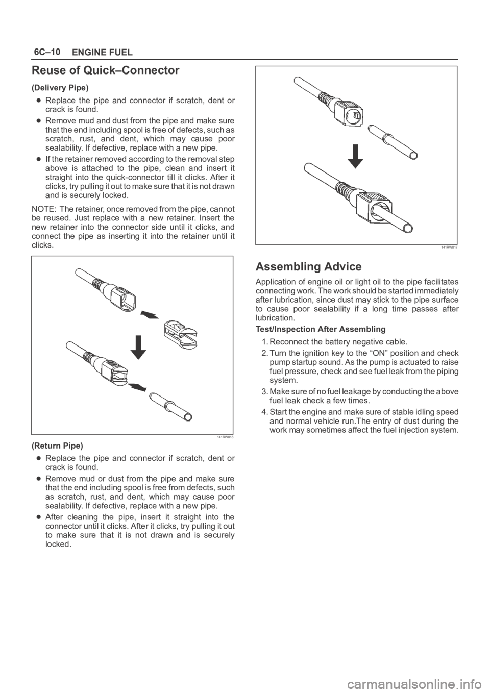
Reuse of Quick–Connector
(Delivery Pipe)
Replace the pipe and connector if scratch, dent or
crack is found.
Remove mud and dust from the pipe and make sure
that the end including spool is free of defects, such as
scratch, rust, and dent, which may cause poor
sealability. If defective, replace with a new pipe.
If the retainer removed according to the removal step
above is attached to the pipe, clean and insert it
straight into the quick-connector till it clicks. After it
clicks, try pulling it out to make sure that it is not drawn
and is securely locked.
NOTE: The retainer, once removed from the pipe, cannot
be reused. Just replace with a new retainer. Insert the
new retainer into the connector side until it clicks, and
connect the pipe as inserting it into the retainer until it
clicks.
141RW018
(Return Pipe)
Replace the pipe and connector if scratch, dent or
crack is found.
Remove mud or dust from the pipe and make sure
that the end including spool is free from defects, such
as scratch, rust, and dent, which may cause poor
sealability. If defective, replace with a new pipe.
After cleaning the pipe, insert it straight into the
connector until it clicks. After it clicks, try pulling it out
to make sure that it is not drawn and is securely
locked.
141RW017
Assembling Advice
Application of engine oil or light oil to the pipe facilitates
connecting work. The work should be started immediately
after lubrication, since dust may stick to the pipe surface
to cause poor sealability if a long time passes after
lubrication.
Test/Inspection After Assembling
1. Reconnect the battery negative cable.
2. Turn the ignition key to the “ON” position and check
pump startup sound. As the pump is actuated to raise
fuel pressure, check and see fuel leak from the piping
system.
3. Make sure of no fuel leakage by conducting the above
fuel leak check a few times.
4. Start the engine and make sure of stable idling speed
and normal vehicle run.The entry of dust during the
work may sometimes affect the fuel injection system.