lock OPEL FRONTERA 1998 Service Manual
[x] Cancel search | Manufacturer: OPEL, Model Year: 1998, Model line: FRONTERA, Model: OPEL FRONTERA 1998Pages: 6000, PDF Size: 97 MB
Page 529 of 6000
4A2B–26DIFFERENTIAL (REAR 244mm)
8. Install pinion mate gears.
Place the pinion mate gears into the differential 180
degrees apart.
9. While holding gears in place, insert differential shaft in
its hole of case. Pull on shaft and rotate case, allowing
gears to turn. Make sure that holes in pinion mate
gears align with holes in case.
It may be necessary to adjust tension on forcing
screw to rotate case.
10. Tighten forcing screw to compress the clutch packs,
to allow installation of tapered washers.
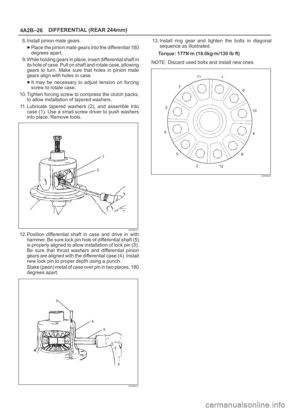
11. Lubricate tapered washers (2), and assemble into
case (1). Use a small screw driver to push washers
into place. Remove tools.
425RW012
12. Position differential shaft in case and drive in with
hammer. Be sure lock pin hole of differential shaft (5)
is properly aligned to allow installation of lock pin (3).
Be sure that thrust washers and differential pinion
gears are aligned with the differential case (4). Install
new lock pin to proper depth using a punch.
S t a k e ( p e e n ) m e t a l o f c a s e o v e r p i n i n t w o p l a c e s , 1 8 0
degrees apart.
425RW013
13. Install ring gear and tighten the bolts in diagonal
sequence as illustrated.
Torque: 177Nꞏm (18.0kgꞏm/130 lb ft)
NOTE: Discard used bolts and install new ones.
425RW033
Page 530 of 6000

DIFFERENTIAL (REAR 244mm)
4A2B–27
Main Data and Specifications
General Specifications
Rear axle
Ty p eBanjo, Semi–floating
Rear axle Size244 mm (9.61 in)
Gear typeHypoid
Gear ratio (to 1)4.100(6VE1 with A/T)
4.300(6VE1 with M/T,4JX1)
Differential typeTwo pinion
Lubricant GradeGL–5: (Standard differential)
GL–5, LSD: (Limited slip differential)
Locking Differential Lubricant80W90 GL–5
(USE Limited Slip Differential Gear Lubricant or Friction
Modifier Organic Additive)
Capacity3.0 liter (2.6 Imp qt/3.2 US qt)
Page 533 of 6000

4A2B–30DIFFERENTIAL (REAR 244mm)
ILLUSTRATIONTOOL NO.
TOOL NAME
5–8840–2573–0
(J–42827)
Pilot;Inner
5–8840–2572–0
(J–42826)
Gage plate
5–8840–0126–0
(J–8001)
Dial indicator
5–8840–2577–0
(J–42825)
Disc (2 required)
5–8840–0128–0
(J–23597–1)
Arbor
5–8840–2574–0
(J–42828)
Installer; Pinion bearing
ILLUSTRATIONTOOL NO.
TOOL NAME
5–8840–2293–0
(J–39209)
Punch; End nut lock
5–8840–2570–0
(J–42829)
Installer; Side bearing
5–8840–2323–0
(J–39602)
Remover; Outer bearing
5–8840–2586–0
(J–39858)
Clutch pack unloading
tool kit Includes
Screw cap, Cap and
Forcing screw
Page 534 of 6000
4B1–1 DRIVE LINE CONTROL SYSTEM (SHIFT ON THE FLY)
DRIVELINE/AXLE
DRIVELINE CONTROL SYSTEM (SHIFT ON THE FLY)
CONTENTS
Service Precaution 4B1–1. . . . . . . . . . . . . . . . . . . . . .
Shift on the Fly System (Lever Type) 4B1–2. . . . . . .
Outline of Shift on the Fly System
(Lever Type) 4B1–2. . . . . . . . . . . . . . . . . . . . . . . . . . .
Shift on the Fly Vacuum Piping and Electric
Equipment (For Lever Control Type) 4B1–3. . . . . .
Vacuum Piping Diagram 4B1–3. . . . . . . . . . . . . . . .
Inspection and Repair 4B1–4. . . . . . . . . . . . . . . . . .
Shift on the Fly System (Push Button Type) 4B1–7.
Outline of Shift on the Fly System
(Push Button Type) 4B1–7. . . . . . . . . . . . . . . . . . . . Functions of Indicator Lamp 4B1–11. . . . . . . . . . . . . . .
Diagnosis 4B1–11. . . . . . . . . . . . . . . . . . . . . . . . . . . . .
Front Axle Diagnosis 4B1–30. . . . . . . . . . . . . . . . . . .
Shift on the Fly Vacuum Piping and Electric
Equipment (For Push Button Type) 4B1–32. . . . . . . .
Vacuum Piping Diagram 4B1–32. . . . . . . . . . . . . . . .
Inspection and Repair 4B1–33. . . . . . . . . . . . . . . . . .
4WD Control Unit (For Push Button Type) 4B1–36. .
4WD Control Unit Associated Parts 4B1–36. . . . . .
Removal 4B1–37. . . . . . . . . . . . . . . . . . . . . . . . . . . . .
Installation 4B1–37. . . . . . . . . . . . . . . . . . . . . . . . . . . .
Service Precaution
WARNING: IF SO EQUIPPED WITH A
SUPPLEMENTAL RESTRAINT SYSTEM (SRS),
REFER TO THE SRS COMPONENT AND WIRING
LOCATION VIEW IN ORDER TO DETERMINE
WHETHER YOU ARE PERFORMING SERVICE ON OR
NEAR THE SRS COMPONENTS OR THE SRS
WIRING. WHEN YOU ARE PERFORMING SERVICE
ON OR NEAR THE SRS COMPONENTS OR THE SRS
WIRING, REFER TO THE SRS SERVICE
INFORMATION. FAILURE TO FOLLOW WARNINGS
COULD RESULT IN POSSIBLE AIR BAG
DEPLOYMENT, PERSONAL INJURY, OR
OTHERWISE UNNEEDED SRS SYSTEM REPAIRS.
CAUTION: Always use the correct fastener in the
proper location. When you replace a fastener, use
ONLY the exact part number for that application.
ISUZU will call out those fasteners that require a
replacement after removal. ISUZU will also call out
the fasteners that require thread lockers or thread
sealant. UNLESS OTHERWISE SPECIFIED, do not
use supplemental coatings (Paints, greases, or other
corrosion inhibitors) on threaded fasteners or
fastener joint interfaces. Generally, such coatings
adversely affect the fastener torque and the joint
clamping force, and may damage the fastener. When
you install fasteners, use the correct tightening
sequence and specifications. Following these
instructions can help you avoid damage to parts and
systems.
Page 535 of 6000

4B1–2
DRIVE LINE CONTROL SYSTEM (SHIFT ON THE FLY)
Shift on the Fly System (Lever Type)
Outline of Shift on the Fly System
(Lever Type)
The shift on the fly system (Lever type) switches between
2 wheel drive (2WD) and 4 wheel drive (4WD) by driver’s
shifting the transfer control lever on the floor.
This system controls below operations.
1. Connecting front wheels to, and disconnecting them
from, the front axles by vacuum actuator.
2. Indicator on instrument panel.
3. 4WD signal to Electronic Hydraulic Control Unit for
brake system (If anti–lock brake system is equipped).
Page 540 of 6000
4B1–7 DRIVE LINE CONTROL SYSTEM (SHIFT ON THE FLY)
Shift on the Fly System (Push Button Type)
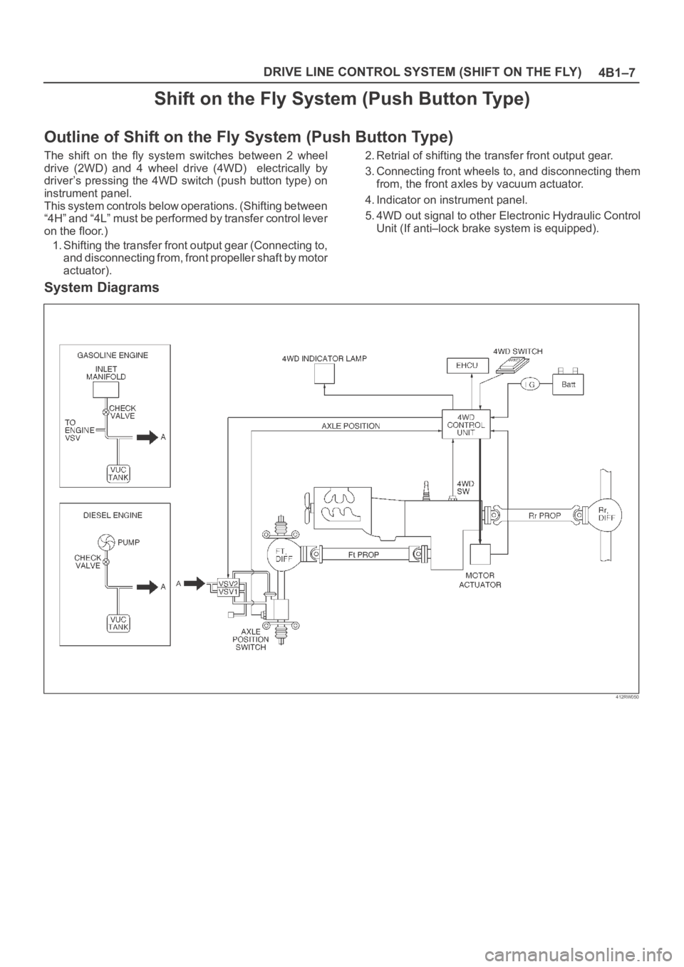
Outline of Shift on the Fly System (Push Button Type)
The shift on the fly system switches between 2 wheel
drive (2WD) and 4 wheel drive (4WD) electrically by
driver’s pressing the 4WD switch (push button type) on
instrument panel.
This system controls below operations. (Shifting between
“4H” and “4L” must be performed by transfer control lever
on the floor.)
1. Shifting the transfer front output gear (Connecting to,
and disconnecting from, front propeller shaft by motor
actuator).2. Retrial of shifting the transfer front output gear.
3. Connecting front wheels to, and disconnecting them
from, the front axles by vacuum actuator.
4. Indicator on instrument panel.
5. 4WD out signal to other Electronic Hydraulic Control
Unit (If anti–lock brake system is equipped).
System Diagrams
412RW050
Page 572 of 6000
4B2–1 DRIVE LINE CONTROL SYSTEM (TOD)
DRIVELINE/AXLE
DRIVELINE CONTROL SYSTEM (TOD)
CONTENTS
Service Precaution 4B2–1. . . . . . . . . . . . . . . . . . . . . .
General Description 4B2–2. . . . . . . . . . . . . . . . . . . . .
System Components 4B2–4. . . . . . . . . . . . . . . . . . . .
Parts Location 4B2–4. . . . . . . . . . . . . . . . . . . . . . . .
Functions of Indicator Lamp 4B2–8. . . . . . . . . . . . . .
Diagnosis 4B2–12. . . . . . . . . . . . . . . . . . . . . . . . . . . . . .
Basic Diagnostic Flow Chart 4B2–16. . . . . . . . . . . . . .
Parts Location 4B2–17. . . . . . . . . . . . . . . . . . . . . . . . . .
Circuit Diagram 4B2–18. . . . . . . . . . . . . . . . . . . . . . . . . Connector List 4B2–21. . . . . . . . . . . . . . . . . . . . . . . . . .
Checking Failed Pin 4B2–23. . . . . . . . . . . . . . . . . . . . .
Checking Failed TOD Control Unit Pin 4B2–26. . . . .
Diagnostic Trouble Codes 4B2–30. . . . . . . . . . . . . . . .
Diagnosis from Trouble Codes 4B2–31. . . . . . . . . . . .
Trouble Diagnosis Depending on The Status
of TOD Indicator 4B2–58. . . . . . . . . . . . . . . . . . . . . . . .
Diagnosis from Symptom 4B2–86. . . . . . . . . . . . . . . . .
Service Precaution
WARNING: IF SO EQUIPPED WITH A
SUPPLEMENTAL RESTRAINT SYSTEM (SRS),
REFER TO THE SRS COMPONENT AND WIRING
LOCATION VIEW IN ORDER TO DETERMINE
WHETHER YOU ARE PERFORMING SERVICE ON OR
NEAR THE SRS COMPONENTS OR THE SRS
WIRING. WHEN YOU ARE PERFORMING SERVICE
ON OR NEAR THE SRS COMPONENTS OR THE SRS
WIRING, REFER TO THE SRS SERVICE
INFORMATION. FAILURE TO FOLLOW WARNINGS
COULD RESULT IN POSSIBLE AIR BAG
DEPLOYMENT, PERSONAL INJURY, OR
OTHERWISE UNNEEDED SRS SYSTEM REPAIRS.
CAUTION: Always use the correct fastener in the
proper location. When you replace a fastener, use
ONLY the exact part number for that application.
ISUZU will call out those fasteners that require a
replacement after removal. ISUZU will also call out
the fasteners that require thread lockers or thread
sealant. UNLESS OTHERWISE SPECIFIED, do not
use supplemental coatings (Paints, greases, or other
corrosion inhibitors) on threaded fasteners or
fastener joint interfaces. Generally, such coatings
adversely affect the fastener torque and the joint
clamping force, and may damage the fastener. When
you install fasteners, use the correct tightening
sequence and specifications. Following these
instructions can help you avoid damage to parts and
systems.
Page 573 of 6000
DRIVE LINE CONTROL SYSTEM (TOD) 4B2–2
General Description
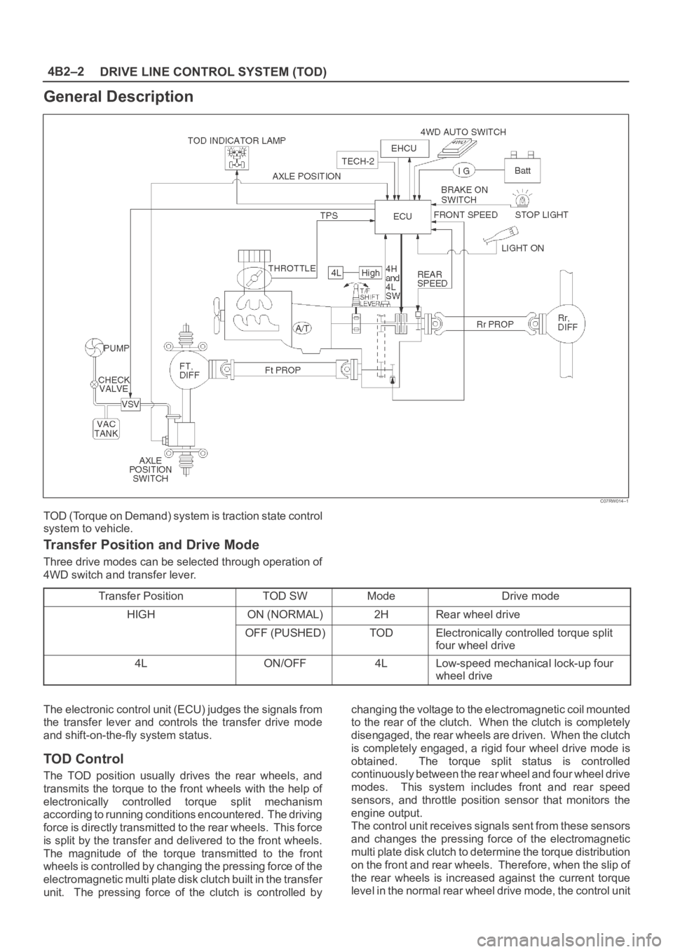
C07RW014–1
TOD (Torque on Demand) system is traction state control
system to vehicle.
Transfer Position and Drive Mode
Three drive modes can be selected through operation of
4WD switch and transfer lever.
Transfer Position
TOD SWModeDrive mode
HIGHON (NORMAL)2HRear wheel drive
OFF (PUSHED)TODElectronically controlled torque split
four wheel drive
4LON/OFF4LLow-speed mechanical lock-up four
wheel drive
The electronic control unit (ECU) judges the signals from
the transfer lever and controls the transfer drive mode
and shift-on-the-fly system status.
TOD Control
The TOD position usually drives the rear wheels, and
transmits the torque to the front wheels with the help of
electronically controlled torque split mechanism
according to running conditions encountered. The driving
force is directly transmitted to the rear wheels. This force
is split by the transfer and delivered to the front wheels.
The magnitude of the torque transmitted to the front
wheels is controlled by changing the pressing force of the
electromagnetic multi plate disk clutch built in the transfer
unit. The pressing force of the clutch is controlled bychanging the voltage to the electromagnetic coil mounted
to the rear of the clutch. When the clutch is completely
disengaged, the rear wheels are driven. When the clutch
is completely engaged, a rigid four wheel drive mode is
obtained. The torque split status is controlled
continuously between the rear wheel and four wheel drive
modes. This system includes front and rear speed
sensors, and throttle position sensor that monitors the
engine output.
The control unit receives signals sent from these sensors
and changes the pressing force of the electromagnetic
multi plate disk clutch to determine the torque distribution
on the front and rear wheels. Therefore, when the slip of
the rear wheels is increased against the current torque
level in the normal rear wheel drive mode, the control unit
Page 575 of 6000

DRIVE LINE CONTROL SYSTEM (TOD) 4B2–4
System Components
Parts Location
A07RW020
Legend
(1) T/F Connector
(2) 4H Switch and 4L Switch
(3) High-Low Planetary Gear Set
(4) Mechanical Lock(5) Multi Plate Disk Clutch Pack
(6) Electromagnetic Coil
(7) Rear Speed Sensor
(8) Front Speed Sensor
Page 576 of 6000
4B2–5 DRIVE LINE CONTROL SYSTEM (TOD)
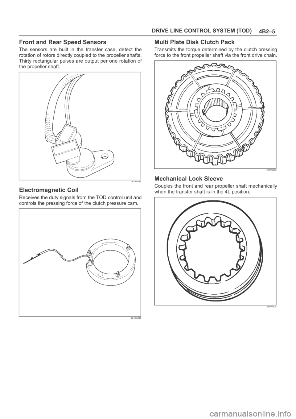
Front and Rear Speed Sensors
The sensors are built in the transfer case, detect the
rotation of rotors directly coupled to the propeller shafts.
Thirty rectangular pulses are output per one rotation of
the propeller shaft.
261RW045
Electromagnetic Coil
Receives the duty signals from the TOD control unit and
controls the pressing force of the clutch pressure cam.
261RW044
Multi Plate Disk Clutch Pack
Transmits the torque determined by the clutch pressing
force to the front propeller shaft via the front drive chain.
262RW029
Mechanical Lock Sleeve
Couples the front and rear propeller shaft mechanically
when the transfer shaft is in the 4L position.
262RW028