lock OPEL FRONTERA 1998 Owner's Manual
[x] Cancel search | Manufacturer: OPEL, Model Year: 1998, Model line: FRONTERA, Model: OPEL FRONTERA 1998Pages: 6000, PDF Size: 97 MB
Page 471 of 6000

4A2A–4
DIFFERENTIAL (REAR 220mm)
Axle Housing
Axle Housing and Associated Parts
420RW022
Legend
(1) Coil Spring and Insulator
(2) Axle Housing Assembly
(3) ABS Speed Sensor and Harness(if equipped)
(4) Nut
(5) Parking Brake Cable
(6) Bolt and Nut
(7) Antilock Brake System (ABS) Connector and
Bracket (if equipped)
(8) Bolt and Nut(9) Nut
(10) Differential Assembly
(11) Axle Shaft Assembly
(12) Brake Disc
(13) Brake Pipe
(14) Brake Caliper
(15) Nut
(16) Breather Hose
(17) Flare Nut
Removal
1. Raise the vehicle and support it with suitable safety
stands.
The hoist must remain under the rear axle housing.
2. Drain brake fluid. Refer to Hydraulic Brakes in Brake
section.
3. Remove rear wheels and tires. Refer to Wheel in
Suspension section.4. Remove propeller shaft. Refer to Rear Propeller
Shaft in this section.
5. Drain the rear axle oil into a proper container.
6. Remove parking brake cable, release the connection
between the cable fixing clip equalizer. Refer to
Parking Brakes in Brake section.
7. Move the clip aside and pull out the breather hose.
Page 472 of 6000

DIFFERENTIAL (REAR 220mm)
4A2A–5
8. Disconnect the ABS connectors (1) and remove the
brackets (2) attached to the frame and center link
(ABS model only).
350RS001
9. Loosen the brake tube flare nut, remove the clip and
take out the brake tube.
10. Remove the shock absorber fixing nut from the axle
housing.
11. Remove the stabilizer linkage mounting nut from the
axle housing.
12. Remove the lateral rod fixing nut from the axle
housing.
13. Remove the center link mounting bolt and nut from
the axle housing.
14. Remove the trailing link fixing bolt and nut from the
axle housing.
15. Jack down and remove the coil spring and insulator.
16. Axle housing assembly can be separated from the
vehicle on completion of steps 1 – 11.
17. Remove the brake caliper fixing bolt (3), loosen the
flare nut (1), release the clip (2) and take out the brake
caliper together with the flexible hose.
306RS001
18. Remove brake disc.
19. Remove antilock brake system speed sensor fixing
bolt and the clip and bracket on the axle housing
(ABS model only).
20. Remove the brake pipe clip and fixing bolt on the axle
housing and take out the brake pipe.
21. Remove the bearing holder fixing nut and take out the
axle shaft assembly, be sure not to damage the oil
seal by the spline of the shaft, Refer to Axle Shaft in
this section.
22. Remove differential assembly, refer to Differential
Assembly in this section.
Oil Seal Replacement
Remove the oil seal, carefully not to damage the housing,
and mount new oil seal using oil seal installer
5–8840–2294–0.
420RW028
Installation
1. Install differential assembly, refer to Differential
Assembly in this section.
2. Install axle shaft assembly then tighten the bearing
holder mounting nut to the specified torque. Be sure
not to damage the oil seal by the spline of the shaft.
Torque: 74Nꞏm (7.5kgꞏm/54lb ft)
3. Install brake pipe.
4. Connect antilock brake system (ABS) speed sensor
and harness, refer to 4–Wheel Anti–Lock Brake
System (ABS) in Brake section (ABS model only).
5. Install brake disc.
6. Install brake caliper. Refer to Disk Brakes in Brake
section.
7. Install axle housing assembly.
8. Install coil spring and insulator.
9. Install the trailing link fixing bolt and nut to the axle
housing. For the procedures in items 9–13, refer to
Suspension section.
10. Install the center link bolt and nut to the axle housing.
Page 475 of 6000

4A2A–8
DIFFERENTIAL (REAR 220mm)
Differential Assembly
Differential Assembly and Associated Parts
425RW055
Legend
(1) Bolt and Nut
(2) Axle Shaft Assembly(3) Parking Brake Cable
(4) Differential Assembly
(5) Nut
Removal
1. Jack up and support the frame with stands.
2. Remove the wheel and tire. Refer to Wheel in
Steering section.
3. Drain the differential oil.
4. Remove the propeller shaft. Refer to Rear Propeller
Shaft in this section.
5. Remove the ABS speed sensor(ABS model only).
Refer to 4–Wheel Anti–lock Brake System (ABS) in
Brake section.6. Remove the parking brake cable fastening clip and
disconnect the equalizer section. Refer to Parking
Brakes in Brake section.
7. Remove the bearing holder fixing nuts.
8. Remove axle shaft assembly, be sure not to damage
the oil seal by axle shaft.
9. Remove differential carrier mounting bolts and nuts.
10. Remove differential assembly.
Page 481 of 6000

4A2A–14
DIFFERENTIAL (REAR 220mm)
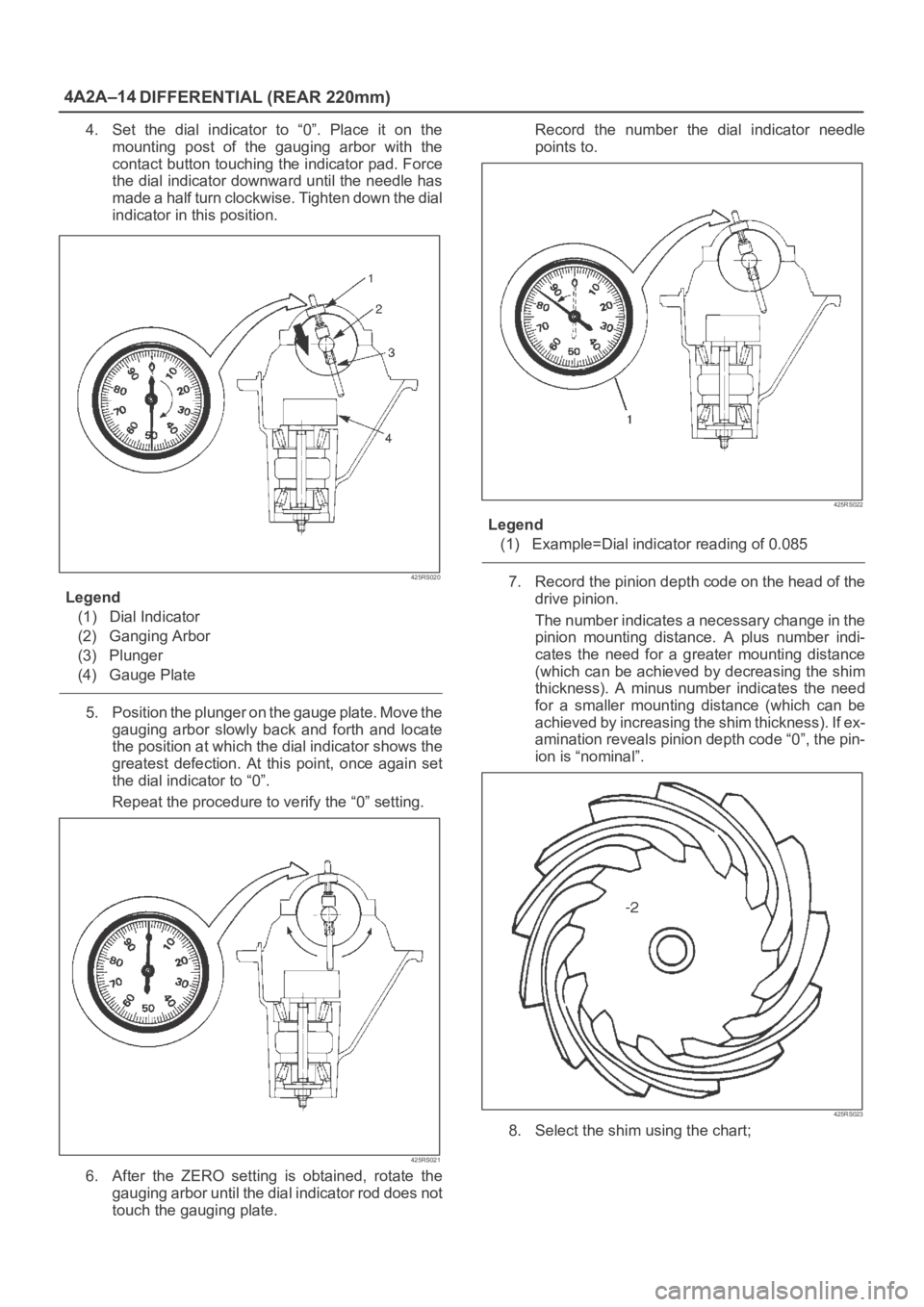
4. Set the dial indicator to “0”. Place it on the
mounting post of the gauging arbor with the
contact button touching the indicator pad. Force
the dial indicator downward until the needle has
made a half turn clockwise. Tighten down the dial
indicator in this position.
425RS020
Legend
(1) Dial Indicator
(2) Ganging Arbor
(3) Plunger
(4) Gauge Plate
5. Position the plunger on the gauge plate. Move the
gauging arbor slowly back and forth and locate
the position at which the dial indicator shows the
greatest defection. At this point, once again set
the dial indicator to “0”.
Repeat the procedure to verify the “0” setting.
425RS021
6. After the ZERO setting is obtained, rotate the
gauging arbor until the dial indicator rod does not
touch the gauging plate.Record the number the dial indicator needle
points to.
425RS022
Legend
(1) Example=Dial indicator reading of 0.085
7. Record the pinion depth code on the head of the
drive pinion.
The number indicates a necessary change in the
pinion mounting distance. A plus number indi-
cates the need for a greater mounting distance
(which can be achieved by decreasing the shim
thickness). A minus number indicates the need
for a smaller mounting distance (which can be
achieved by increasing the shim thickness). If ex-
amination reveals pinion depth code “0”, the pin-
ion is “nominal”.
425RS023
8. Select the shim using the chart;
Page 488 of 6000

DIFFERENTIAL (REAR 220mm)
4A2A–21
Differential Cage Assembly
Disassembled View
415RW034
Legend
(1) Pinion Gear
(2) Thrust Washer
(3) Side Gear
(4) Cross Pin(5) Ring Gear
(6) Bolt
(7) Differential Cage
(8) Lock Pin
Disassembly
1. Remove bolt.
2. Remove ring gear.
3. Remove lock pin, break staking on the lock pin, using
a 5 mm (0.20 in) diameter drill.
425RS042
Page 489 of 6000

4A2A–22
DIFFERENTIAL (REAR 220mm)
4. Remove the cross pin, using a soft metal rod and a
hammer.
425RS043
5. Remove pinion gear.
6. Remove side gear.
7. Remove thrust washer.
Inspection and Repair
Make necessary correction or parts replacement if wear,
damage, corrosion or any other abnormal conditions are
found through inspection.
Check the following parts:
1. Ring gear, pinion gear
2. Bearing
3. Side gear, pinion gear, cross pin
4. Differential cage, carrier
5. Thrust washer
6. Oil seal
Ring gear replacement:
1. The ring gear should always be replaced with the
drive pinion as a set.
2. Clean the ring gear threaded holes to remove the
locking agent.
3. When installing the ring gear, apply LOCTITE 271 or
equivalent to all the threaded area and half of the
unthreaded area of the bolt.
4. Discard used bolts and install new ones.
Torque: 108 Nꞏm (11.0kgꞏm/80 lb ft)5. Tighten the fixing bolts in a diagonal sequence as
illustrated.
415RW036
Clearance between the differential pinion
and the cross pin measurement:
Standard: 0.06 – 0.12 mm (0.002–0.005 in)
Limit: 0.2 mm (0.008 in)
425RS045
Page 490 of 6000

DIFFERENTIAL (REAR 220mm)
4A2A–23
Clearance between the side gear and the
differential box:
Standard: 0.05–0.12 mm (0.002–0.005 in)
Limit: 0.15 mm(0.006 in)
425RS046
Legend
(1) Side Gear
(2) Differential Box
Play in splines between the side gear and
the axle shaft:
Standard: 0.07–0.38 mm(0.003 –0.014 in)
Limit:0.5m (0.02 in)
425RS047
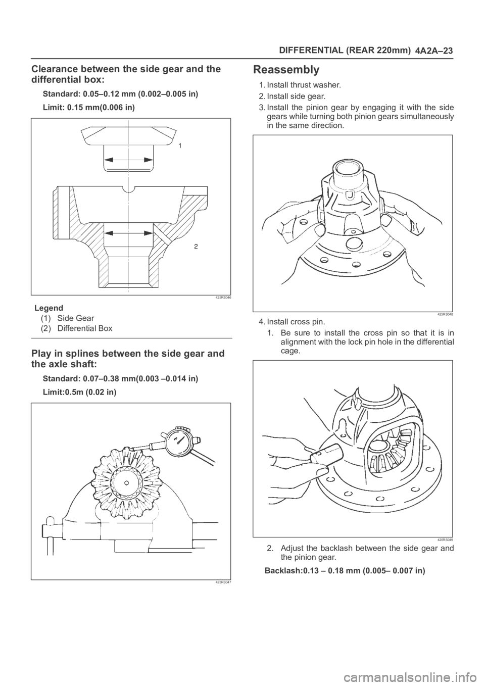
Reassembly
1. Install thrust washer.
2. Install side gear.
3. Install the pinion gear by engaging it with the side
gears while turning both pinion gears simultaneously
in the same direction.
425RS048
4. Install cross pin.
1. Be sure to install the cross pin so that it is in
alignment with the lock pin hole in the differential
cage.
425RS049
2. Adjust the backlash between the side gear and
the pinion gear.
Backlash:0.13 – 0.18 mm (0.005– 0.007 in)
Page 491 of 6000

4A2A–24
DIFFERENTIAL (REAR 220mm)
Thickness of thrust washers available:
0.80 mm, 0.90 mm, 1.00 mm 1.10 mm, 1.20 mm,
1.30 mm (0.031 in, 0.035 in, 0.039 in,0.043 in,
0.047 in, 0.051 in)
425RS050
5. Install lock pin. After lock pin installation, stake the
cage to secure the lock pin.
425RS051
Legend
(1) Staked Portion
(2) Lock Pin
6. Clean the ring gear threaded holes to remove the
locking agent. When installing the ring gear, apply
LOCTITE 271 or equivalent to all the threaded area
and half of the unthreaded area of the bolt.7. Tighten the bolts in diagonal sequence as illustrated.
Torque: 108 Nꞏm (11.0kgꞏm/80 lb ft)
NOTE: Discard used bolts and install new ones.
415RW036
Page 494 of 6000

DIFFERENTIAL (REAR 220mm)
4A2A–27
Pressure ring
425RS057
Legend
(3) Sliding surface with the friction disc. When
nicks or scratches are found, polish with an oil
stone and repair on a level block using a
compound.
(4) Sliding spherical surface with the pinion gear.
(5) Sliding surface with the side gear.
(6) V–shaped groove of the pressure ring and V
–shaped section of the pinion shaft.
(7) Fitting section with the case.
(8) Face contacting the inner surface of the
differential case. Repair burrs and nicks using
an oil stone.
Thrust washer
425RS058
Legend
(9) Sliding surface with the side gear or case.
(10) Peripheral groove of the side gear.
Repair light nicks and burrs using an oil stone.
Case
425RS059
Legend
(11) Contact surface with the spring disc.
(12) Inner groove of the differential cage B.
Repair light nicks and burrs using an oil stone.
425RS060
Page 499 of 6000

4A2A–32
DIFFERENTIAL (REAR 220mm)
Main Data and Specifications
General Specifications
Rear axle
Ty p eBanjo, Semi–floating
Rear axle Size220mm(8.66in)
Gear typeHypoid
Gear ratio (to 1)4.555(6VD1,4JG2–TC)
4.777(4JG2)
Differential typeTwo pinion
Lubricant GradeGL–5: (Standard differential)
GL–5, LSD: (Limited slip differential)
Locking Differential Lubricant80W90 GL–5
(USE Limited Slip Differential Gear Lubricant or Friction
Modifier Organic Additive)
Capacity1.8liter(1.6 Imp qt/1.9 US qt)