Back OPEL FRONTERA 1998 Repair Manual
[x] Cancel search | Manufacturer: OPEL, Model Year: 1998, Model line: FRONTERA, Model: OPEL FRONTERA 1998Pages: 6000, PDF Size: 97 MB
Page 1015 of 6000

6A–59
ENGINE MECHANICAL
Limit: 39.47 mm (1.5539 in)
Exhaust
Standard: 39.30 mm (1.5472 in)
Limit: 39.45 mm (1.5531 in)
014RW047
2. Measure the valve seat contact width. Make the
necessary corrections if the seat contact surface is
damaged or rough or if the contact width wear
exceeds the limit.
Valve seat contact width
Standard: 1.1 mm (0.0433 in)
Limit: 1.7 mm (0.0669 in)
014RS011
Contact Surface Angle on Valve Seat on
Va l v e
1. Measure contact surface angle on valve seat.2. If the measured value exceeds the limit, replace
valve, valve guide and valve seat as a set.
Valve contact surface angle: 45
014RS012
Valve Seat Insert Correction
1. Remove the carbon from the valve seat insert
surface.
2. Use a valve cutter to minimize scratches and other
rough areas. This will bring the contact width back to
the standard value. Remove only the scratches and
rough areas. Do not cut away too much. Take care not
to cut away unblemished areas of the valve seat
surface.
Valve seat angle degree: 90
014RW059
3. Apply abrasive compound to the valve seat insert
surface.
4. Insert the valve into the valve guide.
5.Turn the valve while lapping it to fit the valve seat
insert.
Page 1029 of 6000
6A–73
ENGINE MECHANICAL
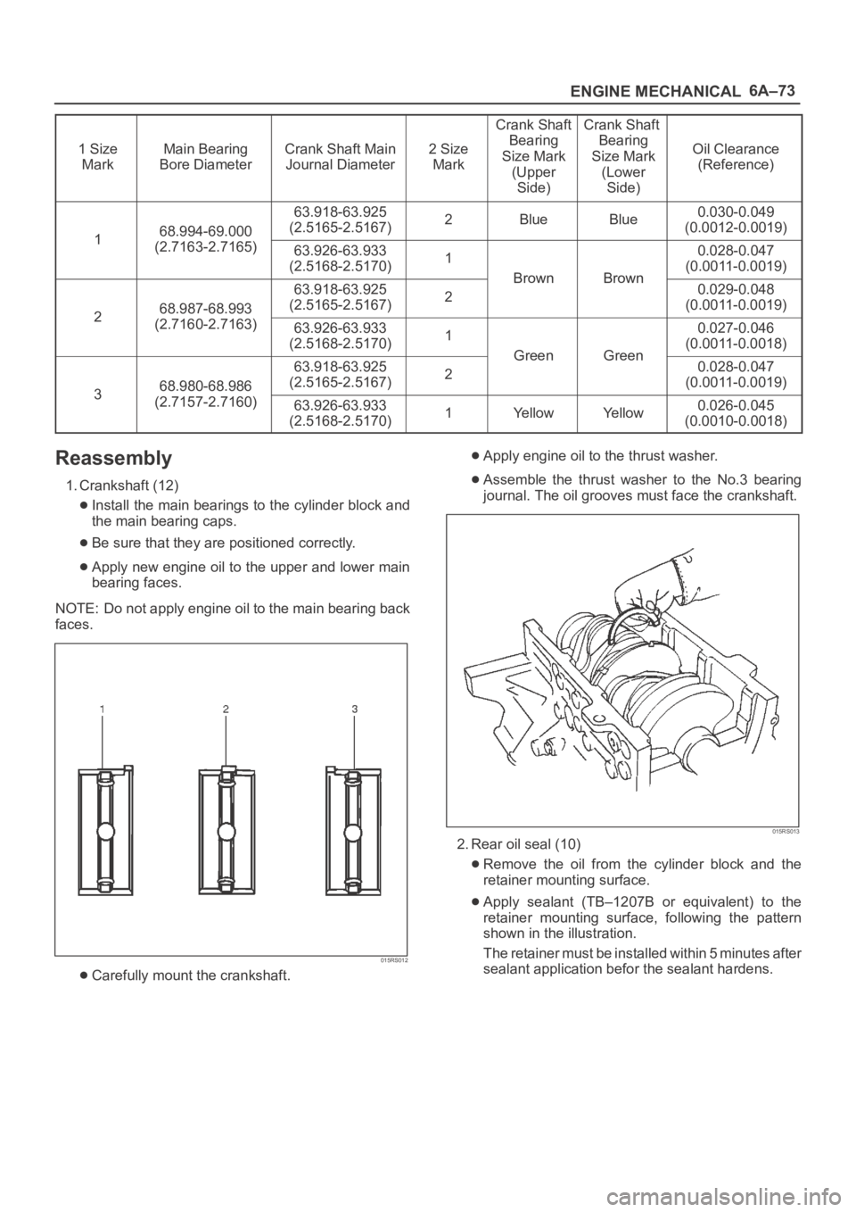
1 Size
MarkMain Bearing
Bore DiameterCrank Shaft Main
Journal Diameter2 Size
Mark
Crank Shaft
Bearing
Size Mark
(Upper
Side)Crank Shaft
Bearing
Size Mark
(Lower
Side)
Oil Clearance
(Reference)
168.994-69.000
63.918-63.925
(2.5165-2.5167)2BlueBlue0.030-0.049
(0.0012-0.0019)
1(2.7163-2.7165)63.926-63.933
(2.5168-2.5170)1
BrownBrown
0.028-0.047
(0.0011-0.0019)
268.987-68.993
63.918-63.925
(2.5165-2.5167)2
BrownBrown0.029-0.048
(0.0011-0.0019)
2(2.7160-2.7163)63.926-63.933
(2.5168-2.5170)1
GreenGreen
0.027-0.046
(0.0011-0.0018)
368.980-68.986
63.918-63.925
(2.5165-2.5167)2
GreenGreen0.028-0.047
(0.0011-0.0019)
3(2.7157-2.7160)63.926-63.933
(2.5168-2.5170)1Ye l l o wYe l l o w0.026-0.045
(0.0010-0.0018)
Reassembly
1. Crankshaft (12)
Install the main bearings to the cylinder block and
the main bearing caps.
Be sure that they are positioned correctly.
Apply new engine oil to the upper and lower main
bearing faces.
NOTE: Do not apply engine oil to the main bearing back
faces.
015RS012
Carefully mount the crankshaft.
Apply engine oil to the thrust washer.
Assemble the thrust washer to the No.3 bearing
journal. The oil grooves must face the crankshaft.
015RS013
2. Rear oil seal (10)
Remove the oil from the cylinder block and the
retainer mounting surface.
Apply sealant (TB–1207B or equivalent) to the
retainer mounting surface, following the pattern
shown in the illustration.
The retainer must be installed within 5 minutes after
sealant application befor the sealant hardens.
Page 1031 of 6000
6A–75
ENGINE MECHANICAL
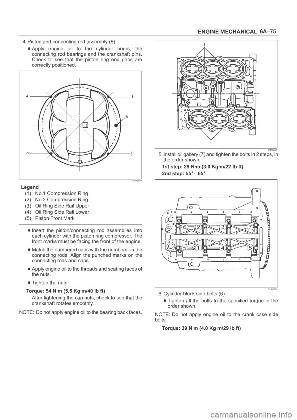
4. Piston and connecting rod assembly (8)
Apply engine oil to the cylinder bores, the
connecting rod bearings and the crankshaft pins.
Check to see that the piston ring end gaps are
correctly positioned.
015RS019
Legend
(1) No.1 Compression Ring
(2) No.2 Compression Ring
(3) Oil Ring Side Rail Upper
(4) Oil Ring Side Rail Lower
(5) Piston Front Mark
Insert the piston/connecting rod assemblies into
each cylinder with the piston ring compressor. The
front marks must be facing the front of the engine.
Match the numbered caps with the numbers on the
connecting rods. Align the punched marks on the
connecting rods and caps.
Apply engine oil to the threads and seating faces of
the nuts.
Tighten the nuts.
Torque: 54 Nꞏm (5.5 Kgꞏm/40 lb ft)
After tightening the cap nuts, check to see that the
crankshaft rotates smoothly.
NOTE: Do not apply engine oil to the bearing back faces.
015RS020
5. Install oil gallery (7) and tighten the bolts in 2 steps, in
the order shown.
1st step: 29 Nꞏm (3.0 Kgꞏm/22 lb ft)
2nd step: 55
65
051RS009
6. Cylinder block side bolts (6)
Tighten all the bolts to the specified torque in the
order shown.
NOTE: Do not apply engine oil to the crank case side
bolts.
Torque: 39 Nꞏm (4.0 Kgꞏm/29 lb ft)
Page 1036 of 6000
6A–80
ENGINE MECHANICAL
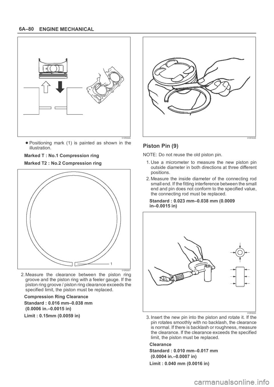
015RS026
Positioning mark (1) is painted as shown in the
illustration.
Marked T : No.1 Compression ring
Marked T2 : No.2 Compression ring
015RS027
2. Measure the clearance between the piston ring
groove and the piston ring with a feeler gauge. If the
piston ring groove / piston ring clearance exceeds the
specified limit, the piston must be replaced.
Compression Ring Clearance
Standard : 0.016 mm–0.038 mm
(0.0006 in.–0.0015 in)
Limit : 0.15mm (0.0059 in)
015RS028
Piston Pin (9)
NOTE: Do not reuse the old piston pin.
1. Use a micrometer to measure the new piston pin
outside diameter in both directions at three different
positions.
2. Measure the inside diameter of the connecting rod
small end. If the fitting interference between the small
end and pin does not conform to the specified value,
the connecting rod must be replaced.
Standard : 0.023 mm–0.038 mm (0.0009
in–0.0015 in)
015RS029
3. Insert the new pin into the piston and rotate it. If the
pin rotates smoothly with no backlash, the clearance
is normal. If there is backlash or roughness, measure
the clearance. If the clearance exceeds the specified
limit, the piston must be replaced.
Clearance
Standard : 0.010 mm–0.017 mm
(0.0004 in.–0.0007 in)
Limit : 0.040 mm (0.0016 in)
Page 1040 of 6000

6A–84
ENGINE MECHANICAL
Tighten the connecting rod cap nuts
Torque : 54 Nꞏm (5.5 Kgꞏm/40 lb ft)
NOTE: Do not apply engine oil to the bearing back faces.
6. Oil gallery, refer to “Crankshaft and main bearing” in
this manual.
7. Oil strainer and O-ring.
8. Oil pipe and O-ring.
9. Install crankcase with oil pan, refer to “Oil pan and
Crankcase” in this manual.
10. Install cylinder head gasket.
11. Install Cylinder head assembly.
Refer to “Cylinder head” in this manual.
Page 1043 of 6000

6A–87
ENGINE MECHANICAL
012RS006
Reassembly
1. Install cylinder block.
2. Install crankshaft.
Install the main bearings to the cylinder block and
the main bearing caps.
Be sure that they are positioned correctly.
Apply new engine oil to the upper and lower main
bearing faces.
NOTE: Do not apply engine oil to the bearing back faces.
015RS012
Legend
(1) Number 1 and 4 main bearing upper and lower.
(2) Number 2 and 3 main bearing upper.
(3) Number 2 and 3 main bearing lower.
Carefully mount the crankshaft.
Apply engine oil to the thrust washer.
Assemble the thrust washer to the No. 3 bearing
journal. The oil grooves must face the crankshaft.
015RS013
3. Install rear oil seal retainer.
Remove oil on cylinder block and retainer fitting
surface.
Apply sealant (TB1207B or equivalent) to retainer
fitting surface as shown in illustration.
The oil seal retainer must be installed within 5
minutes after sealant application before the sealant
hardens.
015RW002
Legend
(1) Around Bolt Holes
(2) Around Dowel Pin
Apply engine oil to oil seal lip and align a dowel pin
hole in the cylinder block with that in the retainer.
Tighten retainer fixing bolts to the specified torque.
Torque: 25 Nꞏm (2.5 Kgꞏm/18.4 lb ft)
Page 1044 of 6000

6A–88
ENGINE MECHANICAL
015RW001
4. Install flywheel
1. Thoroughly clean and remove the oil from the
threads of crankshaft.
2. Remove the oil from the crankshaft and flywheel
mounting faces.
3. Mount the flywheel on the crankshaft and then
install the washer.
4. Holding the crankshaft stationary, tighten the
flywheel bolts in the order shown.
Torque: 54 Nꞏm (5.5 Kgꞏm/40 lb ft)
NOTE: Do not reuse the bolts and do not apply oil or
thread lock to the bolts.
015RS018
5. Install piston and connecting rod assembly.
Apply engine oil to the cylinder bores, the
connecting rod bearings and the crankshaft pins.
NOTE: Do not apply engine oil to the bearing back faces.
Check to see that the piston ring end gaps are
correctly positioned.
015RS019
Legend
(1) No.1 Compression Ring
(2) No.2 Compression Ring
(3) Oil Ring Side Rail Upper
(4) Oil Ring Side Rail Lower
(5) Piston Front Mark
Insert the piston/connecting rod assemblies into
each cylinder with the piston ring compressor.
The front marks (1) must be facing the front of the
engine.
015RS020
6. Install oil gallery and tighten the bolts in 2 steps in the
order shown.
1st step : 29 Nꞏm (3.0 Kgꞏm/22 lb ft)
2nd step : 55
65
Page 1070 of 6000
6C–3
ENGINE FUEL
Adhere to all Notices and Cautions.
All gasoline engines are designed to use only unleaded
gasoline. Unleaded gasoline must be used for proper
emission control system operation.
Its use will also minimize spark plug fouling and extend
engine oil life. Using leaded gasoline can damage the
emission control system and could result in loss of
emission warranty coverage.
All cars are equipped with an Evaporative Emission
Control System. The purpose of the system is to minimize
the escape of fuel vapors to the atmosphere.
Fuel Metering
The Engine Control Module (ECM) is in complete control
of this fuel delivery system during normal driving
conditions.
The intake manifold function, like that of a diesel, is used
only to let air into the engine. The fuel is injected by
separate injectors that are mounted over the intake
manifold.
The Manifold Absolute Pressure (MAP) sensor measures
the changes in the intake manifold pressure which result
from engine load and speed changes, which the MAP
sensor converts to a voltage output.
This sensor generates the voltage to change
corresponding to the flow of the air drawn into the engine.
The changing voltage is transformed into an electric
signal and provided to the ECM.
With receipt of the signals sent from the MAP sensor,
Intake Air Temperature sensor and others, the ECM
determines an appropriate fuel injection pulse width
feeding such information to the fuel injector valves to
effect an appropriate air/fuel ratio.
The Multiport Fuel Injection system utilizes an injection
system where the injectors turn on at every crankshaft
re vol u tion . Th e EC M con tro ls t he in je cto r on tim e so t ha t
the correct amount of fuel is metered depending on
driving conditions.
Two interchangeable “O” rings are used on the injector
that must be replaced when the injectors are removed.
The fuel rail is attached to the top of the intake manifold
and supplies fuel to all the injectors.
Fuel is recirculated through the rail continually while the
engine is running. This removes air and vapors from the
fuel as well as keeping the fuel cool during hot weather
operation.
The fuel pressure control valve that is mounted on the fuel
rail maintains a pressure differential across the injectors
under all operating conditions. It is accomplished by
controlling the amount of fuel that is recirculated back to
the fuel tank based on engine demand.
See Section “Driveability and Emission” for more
information and diagnosis.
Page 1155 of 6000
6E–38
ENGINE DRIVEABILITY AND EMISSIONS
General Service Information
OBD Serviceablity Issues
The list of non-vehicle faults that could affect the
performance of the OBD system has been compiled.
These non-vehicle faults vary from environmental
conditions to the quality of fuel used.
The illumination of the MIL (“Check Engine” lamp) due to
a non-vehicle fault could lead to misdiagnosis of the
vehicle, increased warranty expense and customer
dissatisfaction. The following list of non-vehicle faults
does not include every possible fault and may not apply
equally to all product lines.
Fuel Quality
Using fuel with the wrong octane rating for your vehicle
may cause driveability problems. Many of the major fuel
companies advertise that using “premium” gasoline will
improve the performance of your vehicle. Most premium
fuels use alcohol to increase the octane rating of the fuel.
Although alcohol-enhanced fuels may raise the octane
rating, the fuel’s ability to turn into vapor in cold
temperatures deteriorates. This may affect the starting
ability and cold driveability of the engine.
Low fuel levels can lead to fuel starvation, lean engine
operation, and eventually engine misfire.
Non-OEM Parts
All of the OBD diagnostics have been calibrated to run
with OEM parts. Something as simple as a
high-performance exhaust system that affects exhaust
system back pressure could potentially interfere with the
operation of the EGR valve and thereby turn on the MIL
(“Check Engine” lamp). Small leaks in the exhaust
system near the post catalyst oxygen sensor can also
cause the MIL (“Check Engine” lamp) to turn on.
Aftermarket electronics, such as cellular phones,
stereos, and anti-theft devices, may radiate EMI into the
control system if they are improperly installed. This may
cause a false sensor reading and turn on the MIL (“Check
Engine” lamp).
Environment
Temporary environmental conditions, such as localized
flooding, will have an effect on the vehicle ignition system.
If the ignition system is rain-soaked, it can temporarily
cause engine misfire and turn on the MIL (“Check Engine”
lamp).
Poor Vehicle Maintenance
The sensitivity of OBD diagnostics will cause the MIL
(“Check Engine” lamp) to turn on if the vehicle is not
maintained properly. Restricted air filters, fuel filters, and
crankcase deposits due to lack of oil changes or improper
oil viscosity can trigger actual vehicle faults that were not
previously monitored prior to OBD. Poor vehicle
maintenance can not be classified as a “non-vehicle
fault”, but with the sensitivity of OBD diagnostics, vehicle
maintenance schedules must be more closely followed.Related System Faults
Many of the OBD system diagnostics will not run if the
PCM detects a fault on a related system or component.
One example would be that if the PCM detected a Misfire
fault, the diagnostics on the catalytic converter would be
suspended until Misfire fault was repaired. If the Misfire
fault was severe enough, the catalytic converter could be
damaged due to overheating and would never set a
Catalyst DTC until the Misfire fault was repaired and the
Catalyst diagnostic was allowed to run to completion. If
this happens, the customer may have to make two trips to
the dealership in order to repair the vehicle.
Maintenance Schedule
Refer to the Maintenance Schedule.
Visual / Physical Engine Compartment
Inspection
Perform a careful visual and physical engine
compartment inspection when performing any diagnostic
procedure or diagnosing the cause of an emission test
failure. This can often lead to repairing a problem without
further steps. Use the following guidelines when
performing a visual/physical inspection:
Inspect all vacuum hoses for punches, cuts,
disconnects, and correct routing.
Inspect hoses that are difficult to see behind other
components.
Inspect all wires in the engine compartment for proper
connections, burned or chafed spots, pinched wires,
contact with sharp edges or contact with hot exhaust
manifolds or pipes.
Basic Knowledge of Tools Required
NOTE: Lack of basic knowledge of this powertrain when
performing diagnostic procedures could result in an
incorrect diagnosis or damage to powertrain
components. Do not attempt to diagnose a powertrain
problem without this basic knowledge.
A basic understanding of hand tools is necessary to effec-
tively use this section of the Service Manual.
Serial Data Communications
Class II Serial Data Communications
This vehicle utilizes the “Class II” communication system.
Each bit of information can have one of two lengths: long
or short. This allows vehicle wiring to be reduced by
transmitting and receiving multiple signals over a single
wire. The messages carried on Class II data streams are
also prioritized. If two messages attempt to establish
communications on the data line at the same time, only
the message with higher priority will continue. The device
with the lower priority message must wait. The most
significant result of this regulation is that it provides Tech 2
manufacturers with the capability to access data from any
make or model vehicle that is sold.
Page 1160 of 6000

6E–43 ENGINE DRIVEABILITY AND EMISSIONS
Te c h 2
From 98 MY, Isuzu dealer service departments are
recommended to use Tech 2. Please refer to Tech 2 Tech
2 user guide.
901RW180
Legend
(1) PCMCIA Card
(2) RS 232 Loop Back Connector(3) SAE 16/19 Adaptor
(4) DLC Cable
(5) Tech–2
Tech 2 Features
1. Tech 2 is 12 volt system. Do not apply 24 volt.
2. After connect and/or install Tech 2 body, Vehicle
Communications Interface (VCI) module, PCMCIA
card and DLC connector, connect them to the vehicle
DLC.
3. After power off to the Tech 2, remove and reinstall the
PCMCIA card.
4. The PCMCIA card has a capacity of 10 Megabytes
which is 10 times greater than the memory of the Tech
1 Mass Storage Cartridge.5. The Tech 2 has the capability of two snapshots.
6. The PCMCIA card is sensitive to magnetism and
static electricity, so care should be taken in the
handling of the card.
7. The Tech 2 can plot a graph when replaying a
snapshot.
8. Always return to the Main Menu to press EXIT key
several times before shutting down.
9. To clear Diagnostic Trouble Codes (DTCs), open
Application Menu and press “F1: Clear DTC Info”.