ECO mode OPEL FRONTERA 1998 Repair Manual
[x] Cancel search | Manufacturer: OPEL, Model Year: 1998, Model line: FRONTERA, Model: OPEL FRONTERA 1998Pages: 6000, PDF Size: 97 MB
Page 2153 of 6000

6J – 12 INDUCTION
INSPECTION AND RAPAIR
1. Visually check for cracks/clogs inside intake
manifold.
2. If foreign material is observed, it should be taken
out, and if there are some cracks on the intake
manifold, it must be replaced.
INSTALLATION
1. Install the intake manifold assembly, tighten bolts
and to the specified torque.
Torque: 20 Nꞏm (2.0 kgꞏm / 14.5 lb ft) for bolt
Torque: 20 Nꞏm (2.0 kgꞏm / 14.5 lb ft) for nut
2. Install fuel pipe.
Torque: 4 Nꞏm (0.4 kgꞏm / 2.9 lb ft) for M16 nut
(Apply engine oil)
Torque: 13 Nꞏm (1.3 kgꞏm / 9.4 lb ft) for M10 cap nut
Torque: 14 Nꞏm (1.4 kgꞏm / 10 lb ft) for M10
(Apply engine oil)
3. Install two way check valve.
Torque: 20 Nꞏm (2.0 kgꞏm / 14.5 lb ft)
4. Fill with about 300 cc of engine oil from the high
pressure oil pipe installation port of the oil rail using
an oil filler.
If assembled without filling the oil rail with oil, the
time for engine starting will be longer.
5. Install high pressure oil pipe, then tighten sleeve nut
to the specified torque.
Torque: 29 Nꞏm (3.0 kgꞏm / 21.7 lb ft)
6. Reconnect harness connector to MAP sensor, EGR
vacuum sensor, ETC sensor, Water thermo unit,
IAT sensor and EVRV sensor.
7. Install hoses to EGR valve, EGR vacuum sensor
and Water outlet of heater.
8. Connect PCV hose.
9. Install oil level gauge guide and fix it.
10. Install intercooler assembly.
Refer to “Intercooler” in this manual.
11. Install water hose to thermostat housing and fill with
engine coolant.
Model of Turbocharger IHI RHF5
Turbine Maximum Speed 180,000 rpm
Maximum Inlet Gas Temperature 800 °C (1472 °F)
Vibration Peak (G) criteria Maximum 4 (G) at Turbine Rotor Speed 140,000 rpm
Tolerance Limit of Compressor Blade Height Less then 0.5 mm (0.0197 in)
MAIN DATA AND SPECIFICATIONS
Page 2173 of 6000

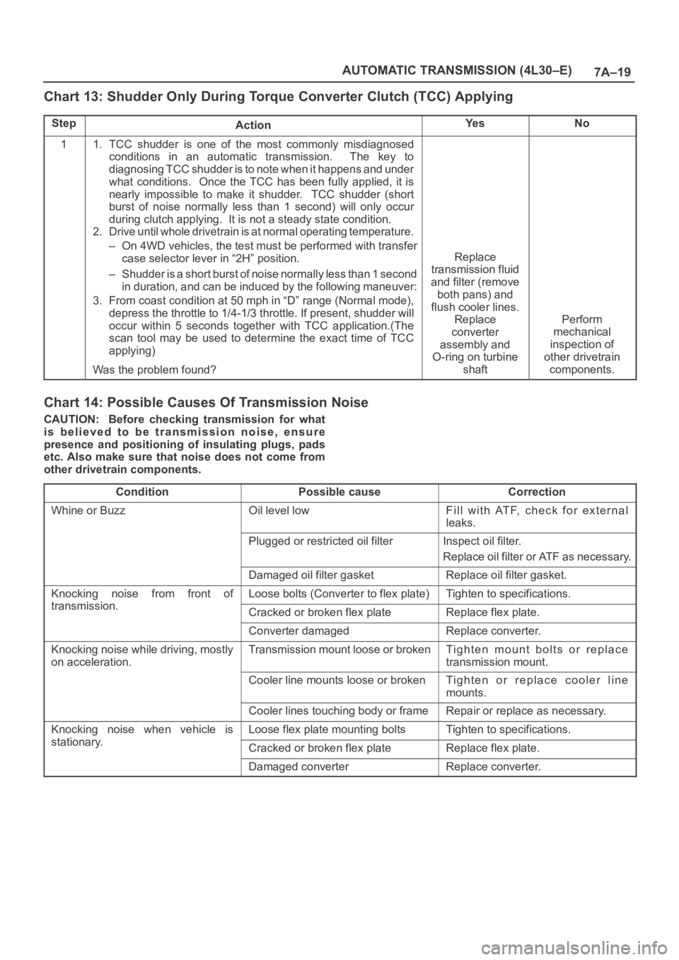
7A–19 AUTOMATIC TRANSMISSION (4L30–E)
Chart 13: Shudder Only During Torque Converter Clutch (TCC) Applying
StepActionYe sNo
11. TCC shudder is one of the most commonly misdiagnosed
conditions in an automatic transmission. The key to
diagnosing TCC shudder is to note when it happens and under
what conditions. Once the TCC has been fully applied, it is
nearly impossible to make it shudder. TCC shudder (short
burst of noise normally less than 1 second) will only occur
during clutch applying. It is not a steady state condition.
2. Drive until whole drivetrain is at normal operating temperature.
– On 4WD vehicles, the test must be performed with transfer
case selector lever in “2H” position.
– Shudder is a short burst of noise normally less than 1 second
in duration, and can be induced by the following maneuver:
3. From coast condition at 50 mph in “D” range (Normal mode),
depress the throttle to 1/4-1/3 throttle. If present, shudder will
occur within 5 seconds together with TCC application.(The
scan tool may be used to determine the exact time of TCC
applying)
Was the problem found?
Replace
transmission fluid
and filter (remove
both pans) and
flush cooler lines.
Replace
converter
assembly and
O-ring on turbine
shaft
Perform
mechanical
inspection of
other drivetrain
components.
Chart 14: Possible Causes Of Transmission Noise
CAUTION: Before checking transmission for what
is believed to be transmission noise, ensure
presence and positioning of insulating plugs, pads
etc. Also make sure that noise does not come from
other drivetrain components.
Condition
Possible causeCorrection
Whine or BuzzOil level lowFill with ATF, check for external
leaks.
Plugged or restricted oil filterInspect oil filter.
Replace oil filter or ATF as necessary.
Damaged oil filter gasketReplace oil filter gasket.
Knocking noise from front of
transmission
Loose bolts (Converter to flex plate)Tighten to specifications.
transmission.Cracked or broken flex plateReplace flex plate.
Converter damagedReplace converter.
Knocking noise while driving, mostly
on acceleration.Transmission mount loose or brokenTighten mount bolts or replace
transmission mount.
Cooler line mounts loose or brokenTighten or replace cooler line
mounts.
Cooler lines touching body or frameRepair or replace as necessary.
Knocking noise when vehicle is
stationary
Loose flex plate mounting boltsTighten to specifications.
stationary.Cracked or broken flex plateReplace flex plate.
Damaged converterReplace converter.
Page 2178 of 6000

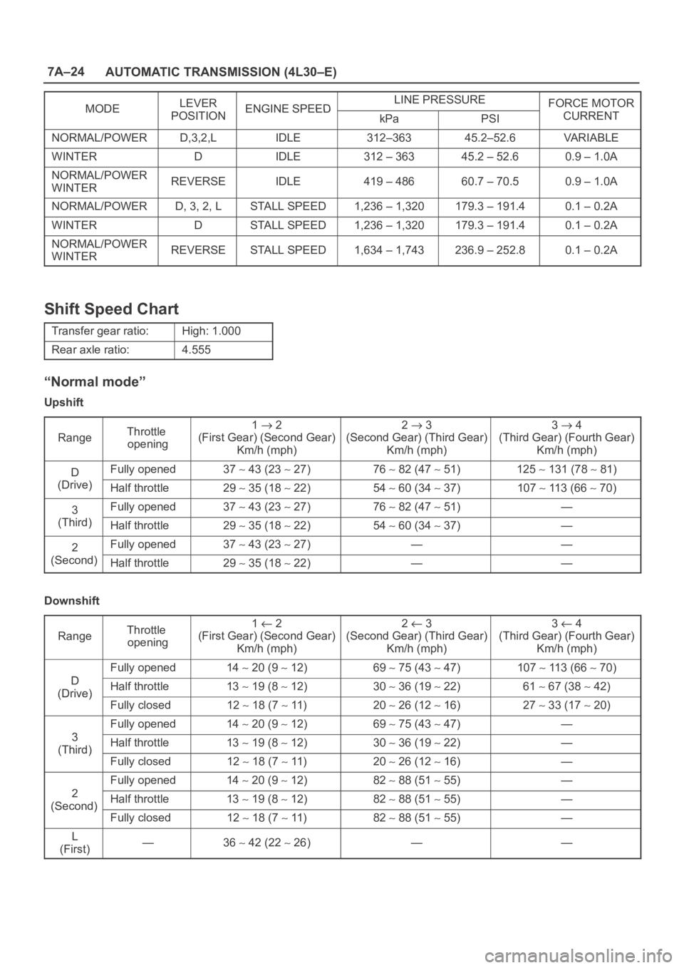
7A–24
AUTOMATIC TRANSMISSION (4L30–E)
MODELEVERENGINE SPEEDLINE PRESSUREFORCE MOTORMODEPOSITIONENGINE SPEEDkPaPSICURRENT
NORMAL/POWERD,3,2,LIDLE312–36345.2–52.6VA R I A B L E
WINTERDIDLE312 – 36345.2 – 52.60.9 – 1.0A
NORMAL/POWER
WINTERREVERSEIDLE419 – 48660.7 – 70.50.9 – 1.0A
NORMAL/POWERD, 3, 2, LSTALL SPEED1,236 – 1,320179.3 – 191.40.1 – 0.2A
WINTERDSTALL SPEED1,236 – 1,320179.3 – 191.40.1 – 0.2A
NORMAL/POWER
WINTERREVERSESTALL SPEED1,634 – 1,743236.9 – 252.80.1 – 0.2A
Shift Speed Chart
Transfer gear ratio:High: 1.000
Rear axle ratio:4.555
“Normal mode”
Upshift
Range
Throttle
opening1 2
(First Gear) (Second Gear)
Km/h (mph)2 3
(Second Gear) (Third Gear)
Km/h (mph)3 4
(Third Gear) (Fourth Gear)
Km/h (mph)
DFully opened37 43 (23 27)76 82 (47 51)125 131 (78 81)
(Drive)Half throttle29 35 (18 22)54 60 (34 37)107 113 (66 70)
3Fully opened37 43 (23 27)76 82 (47 51)—
(Third)Half throttle29 35 (18 22)54 60 (34 37)—
2Fully opened37 43 (23 27)——
(Second)Half throttle29 35 (18 22)——
Downshift
Range
Throttle
opening1 2
(First Gear) (Second Gear)
Km/h (mph)2 3
(Second Gear) (Third Gear)
Km/h (mph)3 4
(Third Gear) (Fourth Gear)
Km/h (mph)
D
Fully opened14 20 (9 12)69 75 (43 47)107 113 (66 70)
D
(Drive)Half throttle13 19 (8 12)30 36 (19 22)61 67 (38 42)(Drive)
Fully closed12 18 (7 11)20 26 (12 16)27 33 (17 20)
3
Fully opened14 20 (9 12)69 75 (43 47)—
3
(Third)Half throttle13 19 (8 12)30 36 (19 22)—(Third)
Fully closed12 18 (7 11)20 26 (12 16)—
2
Fully opened14 20 (9 12)82 88 (51 55)—
2
(Second)Half throttle13 19 (8 12)82 88 (51 55)—(Second)
Fully closed12 18 (7 11)82 88 (51 55)—
L
(First)—36 42 (22 26)——
Page 2179 of 6000

7A–25 AUTOMATIC TRANSMISSION (4L30–E)
“Power mode”
Upshift
Range
Throttle
opening1 2
(First Gear) (Second Gear)
Km/h (mph)2 3
(Second Gear) (Third Gear)
Km/h (mph)3 4
(Third Gear) (Fourth Gear)
Km/h (mph)
DFully opened41 47 (25 29)79 85 (49 53)125 131 (78 81)
(Drive)Half throttle36 42 (22 26)69 75 (43 47)11 9 125 (74 78)
3Fully opened41 47 (25 29)79 85 (49 53)—
(Third)Half throttle36 42 (22 26)69 75 (43 47)—
2Fully opened41 47 (25 29)——
(Second)Half throttle36 42 (22 26)——
Downshift
Range
Throttle
opening1 2
(First Gear) (Second Gear)
Km/h (mph)2 3
(Second Gear) (Third Gear)
Km/h (mph)3 4
(Third Gear) (Fourth Gear)
Km/h (mph)
D
Fully opened28 34 (17 21)70 76 (43 47)11 5 121 (71 75)
D
(Drive)Half throttle20 26 (12 16)46 52 (29 32)90 96 (56 60)(Drive)
Fully closed12 18 (7 11)22 28 (14 17)43 50 (27 31)
3
Fully opened28 34 (17 21)70 76 (43 47)—
3
(Third)Half throttle20 26 (12 16)46 52 (29 32)—(Third)
Fully closed12 18 (7 11)22 28 (14 17)—
2
Fully opened28 34 (17 21)82 88 (51 55)—
2
(Second)Half throttle20 26 (12 16)82 88 (51 55)—(Second)
Fully closed12 18 (7 11)82 88 (51 55)—
L
(First)—36 42 (22 26)——
“Winter mode”
D range, winter mode ON OFF27 33 Km/h (17 20 mph)
Page 2231 of 6000

7A–77 AUTOMATIC TRANSMISSION (4L30–E)
Main Data And Specification
General Specifications
Remarks
ModelTHM 4L30–E
EngineV6 3.2L 6VD1DOHC
Ty p eAutomatic four speed overdrive in
4th gear lock–up clutch torque con-
verter
Shift controlHydraulic
Control systemsShift patternElectronicControl systemsShift qualityElectronic
Lock–up clutchElectronic
1st2.856
2nd1.618
Gear ratio3rd1.000
4th (O/D)0.723
Reverse2.000
Gear setNoiseless, high torque capability
Oil usedNameAT F D E X R O N–IIIOil usedQ’ty liter (qt)8.6 (9.1)
Torque converter2,100 150Stall speed (rpm)
Reverse clutchRC4
Second clutchC26Number of discsThird clutchC36Number of discs
Brake bandDouble wrap
Fourth clutchC42Number of discsOverrun clutchOC1Number of discs
OverdriveOFW10Number of rollers
PrincipalPFW26Number of sprags
Input sun gear30
Pinion gear19
Ravigneaux plan-Long pinion23g
etary gear setRing gear90
Long pinion19Number of teeth
Output sun gear46
Odi l
Sun gear31
Overdrive plane-
tary gear setPinion gear24tary gear set
Ring gear81
Page 2254 of 6000

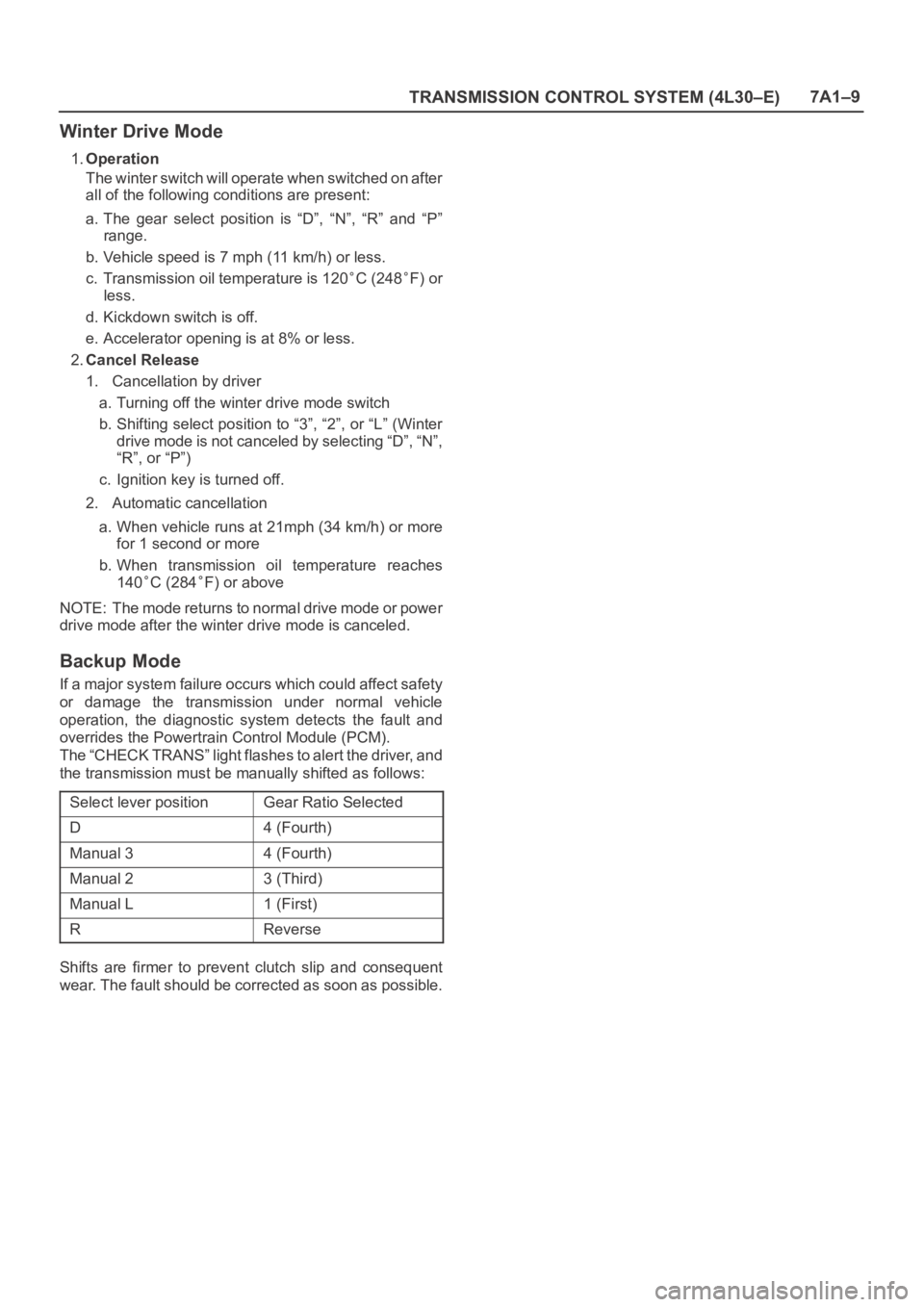
TRANSMISSION CONTROL SYSTEM (4L30–E)7A1–9
Winter Drive Mode
1.Operation
The winter switch will operate when switched on after
all of the following conditions are present:
a. The gear select position is “D”, “N”, “R” and “P”
range.
b. Vehicle speed is 7 mph (11 km/h) or less.
c. Transmission oil temperature is 120
C (248F) or
less.
d. Kickdown switch is off.
e. Accelerator opening is at 8% or less.
2.Cancel Release
1. Cancellation by driver
a. Turning off the winter drive mode switch
b. Shifting select position to “3”, “2”, or “L” (Winter
drive mode is not canceled by selecting “D”, “N”,
“R”, or “P”)
c. Ignition key is turned off.
2. Automatic cancellation
a. When vehicle runs at 21mph (34 km/h) or more
for 1 second or more
b. When transmission oil temperature reaches
140
C (284F) or above
NOTE: The mode returns to normal drive mode or power
drive mode after the winter drive mode is canceled.
Backup Mode
If a major system failure occurs which could affect safety
or damage the transmission under normal vehicle
operation, the diagnostic system detects the fault and
overrides the Powertrain Control Module (PCM).
The “CHECK TRANS” light flashes to alert the driver, and
the transmission must be manually shifted as follows:
Select lever position
Gear Ratio Selected
D4 (Fourth)
Manual 34 (Fourth)
Manual 23 (Third)
Manual L1 (First)
RReverse
Shifts are firmer to prevent clutch slip and consequent
wear. The fault should be corrected as soon as possible.
Page 2267 of 6000

7A1–22
TRANSMISSION CONTROL SYSTEM (4L30–E)
connection or loose wiring. Terminals and grounds should
always be the prime suspect. Intermittents rarely occur
inside sophisticated electronic components such as the
PCM.
Use the DTC information to understand which wires and
sensors are involved.
When an intermittent problem is encountered, check
suspect circuits for:
1. Poor terminal to wire connection.
2. Terminals not fully seated in the connector body
(backed out).
3. Improperly formed or damaged terminals.
4. Loose, dirty, or corroded ground connections:
HINT: Any time you have an intermittent in more than
one circuit, check whether the circuits share a
common ground connection.
5. Pinched or damaged wires.
6. Electro–Magnetic Interference (EMI):
HINT: Check that all wires are properly routed away
from spark plug wires, distributor wires, coil, and
generator. Also check for improperly installed
electrical options, such as lights, 2–way radios, etc.Use the F3 SNAPSHOT mode of the Tech2 to help isolate
the cause of an intermittent fault. The snapshot mode will
record information before and after the problem occurs.
Set the snapshot to “trigger” on the suspect DTC. If you
notice the reported symptom during the test drive, trigger
the snapshot manually.
After the snapshot has been triggered, command the
Tech2 to play back the flow of data recorded from each of
the various sensors. Signs of an intermittent fault in a
sensor circuit are sudden unexplainable jump in data
values out of the normal range.
Transmission And PCM Identification
The chart below contains a list of all important information
concerning rear axle ratio, Powertrain Control Module
(PCM), and transmission identification.
VEHICLE
Rr axlePCMTRANSMISSION
Ty p eEngine
Rr axle
RatioISUZU Parts No.Calibration
CodeIsuzu Part No.Model Code
Isuzu /
Trooper3.2L V64.555
8–16254–949–0
8–16254–749–0
8–16253–989–0
G208–96018–272–3FP (4X4)
Page 2270 of 6000

TRANSMISSION CONTROL SYSTEM (4L30–E)7A1–25
DTC P0218 Transmission Fluid Over Temperature
D07RW029
Circuit Description
The Transmission Fluid Temperature (TFT) sensor is a
thermister that controls the signal voltage to the PCM.
The PCM supplies a 5–volt reference to the sensor on
circuit RED/BLK–GRN/RED. When the transmission fluid
is cold, the sensor resistance is high and the PCM will
sense high signal voltage. As the fluid temperature
warms to a normal transmission operating temperature of
100
C (212F), the sensor resistance becomes less and
the voltage decreases to 1.5 to 2.0 volts.
This DTC detects a high transmission temperature for a
long period of time. This is a type “D” DTC.
Conditions For Setting The DTC
No TFT DTCs P0712 or P0713.
TFT is greater than 135C (275F).
All conditions met for 21 seconds.
Action Taken When The DTC Sets
Hot mode TCC Shift Pattern.
The PCM will not illuminate the CHECK TRANS
Lamp.
ATF Lamp ON. (TFT is greater than 145C (293F).)
Disable E–side TCC OFF request.
Conditions For Clearing The DTC
The DTC can be cleared from the PCM history by
using a scan tool.
The DTC will be cleared from history when the vehicle
has achieved 40 warm–up cycles without a failure
reported.
The PCM will cancel the DTC default actions when
the fault no longer exists and the ignition is cycled “off”
long enough to power down the PCM.
Diagnostic Aids
Inspect the wiring for poor electrical connections at
the PCM and at the transmission 16–way connector.
Look for possible bent, backed out, deformed, or
damaged terminals. Check for weak terminal tension
as well.
Also check for a chafed wire that could short to bare
metal or other wiring. Inspect for a broken wire inside
the insulation.
When diagnosing for a possible intermittent short or
open condition, move the wiring harness while
observing test equipment for a change.
Check harness routing for a potential short to ground
in circuit RED/BLK–GRN/RED.
Scan tool TFT sensor temperature should rise
steadily to about 100
C (212F), then stabilize.
Check for a “skewed” (mis–scaled) sensor by
comparing the TFT sensor temperature to the
ambient temperature after a vehicle cold soak. A
“skewed” sensor can cause delayed garage shifts or
TCC complaints.
Check for a possible torque converter stator problem.
Verify customer driving habits, trailer towing, etc.
Test Description
The numbers below refer to the step numbers on the
diagnostic chart.
3. This test checks for a “skewed” sensor or shorted
circuit.
4. This test simulates a TFT DTC P0713.
Page 2275 of 6000

7A1–30
TRANSMISSION CONTROL SYSTEM (4L30–E)
DTC P0705 Transmission Range Switch (Mode Switch) Illegal Position
D07RW031
Circuit Description
The range switch supplies the Powertrain Control
Module (PCM) with information regarding the selector
lever position: P, R, N, D 3, 2 or L. The selector lever
position is indicated by the state of four ON/OFF
contracts. The range switch is located on one side of
the transmission. It is on the transmission manual
shaft and is fixed to the main case.
The range switch is also used to provide the
information P or N to the engine crank wiring. The
engine can be cranked only if connector M–25
terminal 4(H) is connected to terminal 1(E) which is
connected to ground.
The range switch is also used to provide the backup
lamp power in reverse. This is why the range switch is
supplied through a 10A fuse (C–3). This fuse can
burn due to a short circuit in the backup lamp.
This DTC detects when a fuse is open or the range switch
circuit does not work. This is a type “D” DTC.
Conditions For Setting The DTC
Range switch illegal positions met for 5 seconds.
Action Taken When The DTC Sets
Default to D position.
Inhibit torque management.
Maximum line pressure.
The PCM will not illuminate the CHECK TRANS
Lamp.
Conditions For Clearing The DTC
The DTC can be cleared from the PCM history by
using a scan tool.
The DTC will be cleared from history when the vehicle
has achieved 40 warmup cycles without a failure
reported.
The PCM will cancel the DTC default actions when
the fault no longer exists and the ignition is cycled “off”
long enough to power down the PCM.
Diagnostic Aids
Refer to accompanying chart for the normal range
signals and the illegal combinations.
Inspect the wiring for poor electrical connections at
the PCM and at the transmission 8–way connector.
Look for possible bent, backed out, deformed or
damaged terminals. Check for weak terminal tension
as we ll. A lso ch eck fo r a ch af e d w ire th at cou l d s ho r t
to bare metal or other wiring. Inspect for a broken wire
inside the insulation.
When diagnosing for a possible intermittent short or
open condition, move the wiring harness while
observing test equipment for a change.
Page 2276 of 6000

TRANSMISSION CONTROL SYSTEM (4L30–E)7A1–31
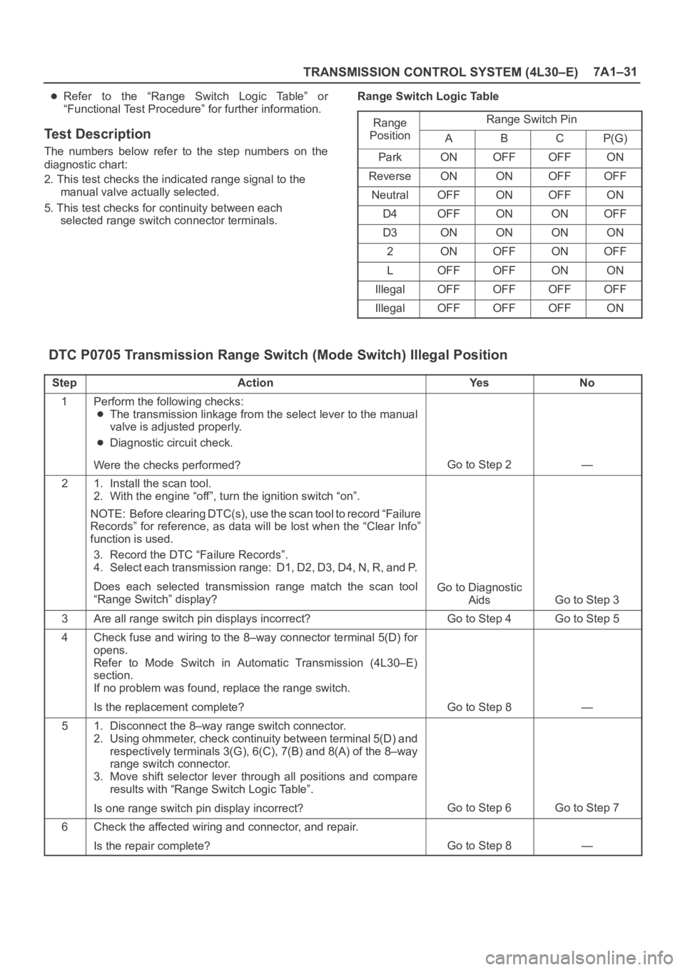
Refer to the “Range Switch Logic Table” or
“Functional Test Procedure” for further information.
Test Description
The numbers below refer to the step numbers on the
diagnostic chart:
2. This test checks the indicated range signal to the
manual valve actually selected.
5. This test checks for continuity between each
selected range switch connector terminals.Range Switch Logic Table
Range
Range Switch Ping
PositionABCP(G)
ParkONOFFOFFON
ReverseONONOFFOFF
NeutralOFFONOFFON
D4OFFONONOFF
D3ONONONON
2ONOFFONOFF
LOFFOFFONON
IllegalOFFOFFOFFOFF
IllegalOFFOFFOFFON
DTC P0705 Transmission Range Switch (Mode Switch) Illegal Position
StepActionYe sNo
1Perform the following checks:
The transmission linkage from the select lever to the manual
valve is adjusted properly.
Diagnostic circuit check.
Were the checks performed?
Go to Step 2—
21. Install the scan tool.
2. With the engine “off”, turn the ignition switch “on”.
NOTE: Before clearing DTC(s), use the scan tool to record “Failure
Records” for reference, as data will be lost when the “Clear Info”
function is used.
3. Record the DTC “Failure Records”.
4. Select each transmission range: D1, D2, D3, D4, N, R, and P.
Does each selected transmission range match the scan tool
“Range Switch” display?
Go to Diagnostic
Aids
Go to Step 3
3Are all range switch pin displays incorrect?Go to Step 4Go to Step 5
4Check fuse and wiring to the 8–way connector terminal 5(D) for
opens.
Refer to Mode Switch in Automatic Transmission (4L30–E)
section.
If no problem was found, replace the range switch.
Is the replacement complete?
Go to Step 8—
51. Disconnect the 8–way range switch connector.
2. Using ohmmeter, check continuity between terminal 5(D) and
respectively terminals 3(G), 6(C), 7(B) and 8(A) of the 8–way
range switch connector.
3. Move shift selector lever through all positions and compare
results with “Range Switch Logic Table”.
Is one range switch pin display incorrect?
Go to Step 6Go to Step 7
6Check the affected wiring and connector, and repair.
Is the repair complete?
Go to Step 8—