battery location OPEL FRONTERA 1998 Repair Manual
[x] Cancel search | Manufacturer: OPEL, Model Year: 1998, Model line: FRONTERA, Model: OPEL FRONTERA 1998Pages: 6000, PDF Size: 97 MB
Page 2552 of 6000

LIGHTING SYSTEM8A–13
Luggage Room Light Bulb
Removal
1. Disconnect the battery ground cable.
2. Remove the lens(2) by releasing the locks at four
locations.
3. Remove the bulb(1).
803RS007
Installation
To install, follow the removal steps in the reverse order.
Courtesy Light Bulb
Removal
1. Disconnect the battery ground cable.
2. Remove two screws to remove the lens(1).
3. Pull out the bulb(2) from the socket.
805RS006
Installation
To install, follow the removal steps in the reverse order.
Page 2571 of 6000

8B–2WIPER/WASHER SYSTEM
Service Precaution
WARNING: IF SO EQUIPPED WITH A
SUPPLEMENTAL RESTRAINT SYSTEM (SRS),
REFER TO THE SRS COMPONENT AND WIRING
LOCATION VIEW IN ORDER TO DETERMINE
WHETHER YOU ARE PERFORMING SERVICE ON OR
NEAR THE SRS COMPONENTS OR THE SRS
WIRING. WHEN YOU ARE PERFORMING SERVICE
ON OR NEAR THE SRS COMPONENTS OR THE SRS
WIRING, REFER TO THE SRS SERVICE
INFORMATION. FAILURE TO FOLLOW WARNINGS
COULD RESULT IN POSSIBLE AIR BAG
DEPLOYMENT, PERSONAL INJURY, OR
OTHERWISE UNNEEDED SRS SYSTEM REPAIRS.CAUTION: Always use the correct fastener in the
proper location. When you replace a fastener, use
ONLY the exact part number for that application.
ISUZU will call out those fasteners that require a
replacement after removal. ISUZU will also call out
the fasteners that require thread lockers or thread
sealant. UNLESS OTHERWISE SPECIFIED, do not
use supplemental coatings (Paints, greases, or other
corrosion inhibitors) on threaded fasteners or
fastener joint interfaces. Generally, such coatings
adversely affect the fastener torque and the joint
clamping force, and may damage the fastener. When
you install fasteners, use the correct tightening
sequence and specifications. Following these
instructions can help you avoid damage to parts and
systems.
Windshield Wiper/Washer System
General Description
The circuit consists of the starter switch, windshield wiper
& washer switch, windshield wiper motor, windshield
washer motor and windshield intermittent relay.When the wiper & washer switch is turned on with the
starter switch on, the battery voltage is applied to the
wiper motor to activate the wiper.
The washer motor squirts glass cleaning fluid while the
washer switch is being pushed. The intermittent relay is
used to control motion of the wiper.
Windshield Wiper And Washer Switch
Removal and Installation
Refer to the Lighting Switch (Combination Switch) in
Lighting System section.
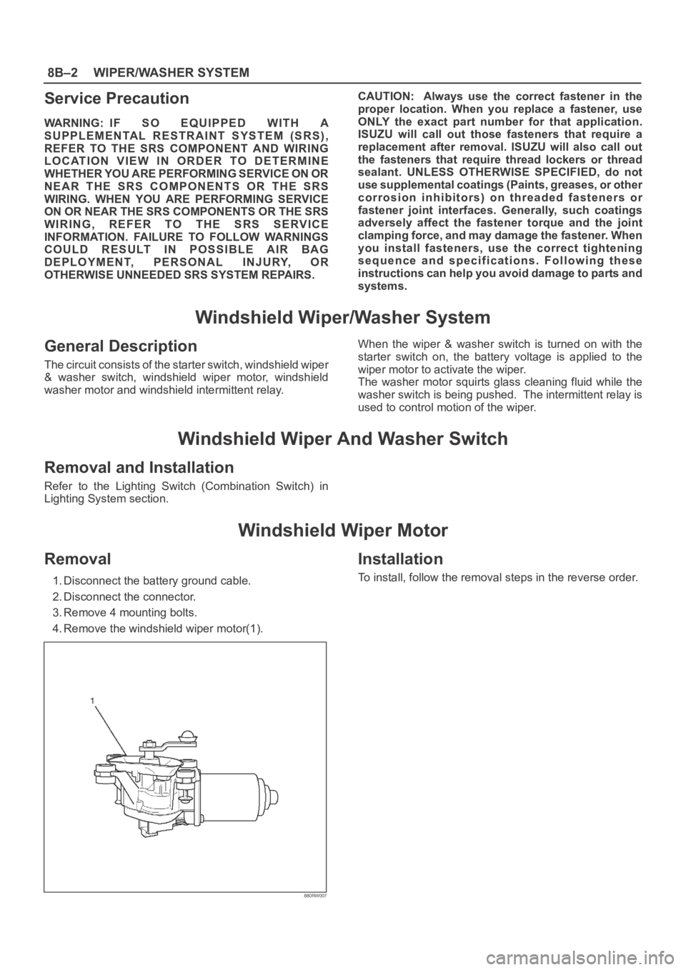
Windshield Wiper Motor
Removal
1. Disconnect the battery ground cable.
2. Disconnect the connector.
3. Remove 4 mounting bolts.
4. Remove the windshield wiper motor(1).
880RW007
Installation
To install, follow the removal steps in the reverse order.
Page 2597 of 6000

The chassis electrical system is a 12–volt system with a
negative ground polarity.
Wire size are appropriate to respective circuits, and
classified by color. (The classification of harnesses by
color is shown on the circuit diagram for ease of harness
identification.)
The wire size is determined by load capacity and the
length of wire required.
The vehicle harnesses are: body harness, chassis
harness, engine room harness, instrument harness,
transmission harness, engine ECGI harness, dome light
harness, door harness, rear body harness, tailgate
harness, SRS harness and battery cables.
The harnesses are protected either by tape or corrugated
tube, depending on harness location.
The circuit for each system consists of the power source,
wire, fuse, relay, switch, load parts and ground, all of
which are shown on the circuit diagram.
In this section, each electrical device is classified by
system.
For major parts shown on the circuit based on the circuit
diagram for each system, a summary, diagnosis of
troubles and inspection procedures are detailed.
Notes for Working on Electrical
Items
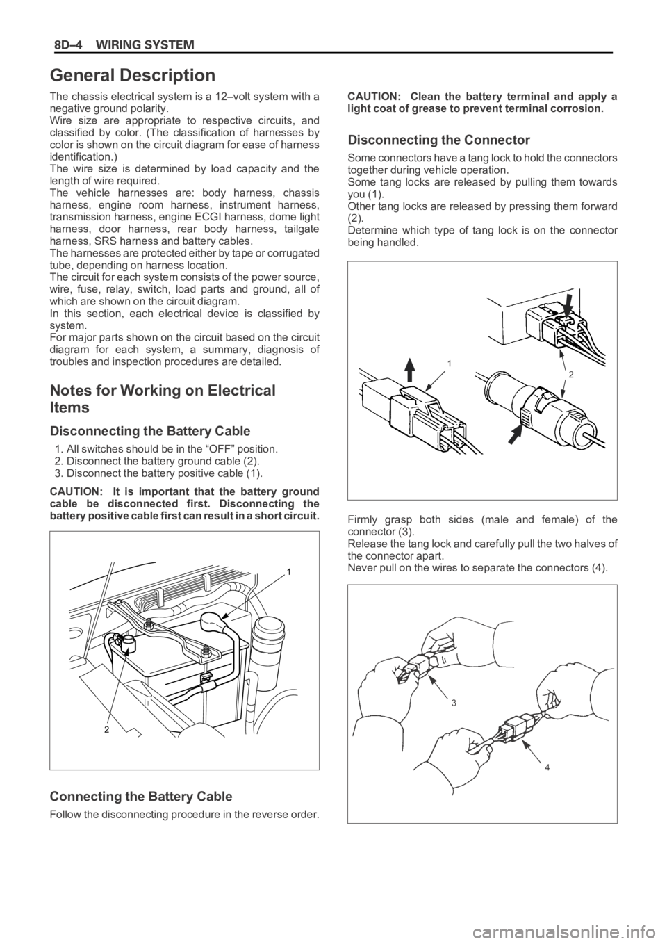
Disconnecting the Battery Cable
1. All switches should be in the “OFF” position.
2. Disconnect the battery ground cable (2).
3. Disconnect the battery positive cable (1).
CAUTION: It is important that the battery ground
cable be disconnected first. Disconnecting the
battery positive cable first can result in a short circuit.
Connecting the Battery Cable
Follow the disconnecting procedure in the reverse order.CAUTION: Clean the battery terminal and apply a
light coat of grease to prevent terminal corrosion.
Disconnecting the Connector
Some connectors have a tang lock to hold the connectors
together during vehicle operation.
Some tang locks are released by pulling them towards
you (1).
Other tang locks are released by pressing them forward
(2).
Determine which type of tang lock is on the connector
being handled.
Firmly grasp both sides (male and female) of the
connector (3).
Release the tang lock and carefully pull the two halves of
the connector apart.
Never pull on the wires to separate the connectors (4).
2
1
General Description
1
2
3
4
Page 2609 of 6000

Circuit Breaker
The circuit breaker is a protective device designed to
open the circuit when a current load is in excess of rated
breaker capacity. If there is a short or other type of
overload condition in the circuit, the excessive current will
open the circuit between the circuit breaker terminals.
The reset knob (1) pops out when the circuit is open. Push
the reset knob in place to restore the circuit after repairing
it.
Relay
Battery and load location may require that a switch be
placed some distance from either component. This
means a longer wire and a higher voltage drop (1).
The installation of a relay between the battery and the
load reduces the voltage drop (2).
Because the switch controls the relay, amperage through
the switch can be reduced.
LOAD
12LOAD
RELAY
D08RW404
1
Page 3205 of 6000

8F–10BODY STRUCTURE
Parts Location (W/Rear Combination Light and License Light)
690RW010
Legend
(1) Back Bar
(2) Rear Combination Light Back Plate
(3) Rear Bumper Retainer
(4) Reinforce Assembly
(5) Rear Bumper Slider Brackets
(6) Rear Combination Light Assembly
(7) License Light
(8) Reinforce Lower Screws(9) Reinforce Upper Bolts
(10) Rear Step
(11) Rear Step Clips
(12) Rear Bumper Fascia Bracket Screws
(13) Rear Bumper Assembly
(14) Rear Bumper Side Covers
(15) Rear Bumper Fascia Brackets
(16) Mud Flaps
(17) Rear Bumper Assembly Fixing Bolts
Removal
1. Disconnect battery ground cable.
2. Remove rear bumper side covers.3. Remove mud flaps.Remove three screws.
4. Remove rear bumper fascia bracket screws.
Page 3207 of 6000

8F–12BODY STRUCTURE
Parts Location (W/Rear Combination Light)
690RW012
Legend
(1) Back Bar
(2) Rear Combination Light Back Plate
(3) Rear Bumper Retainer
(4) Reinforce Assembly
(5) Rear Bumper Slider Brackets
(6) Rear Combination Light Assembly
(7) Rear Step Clips
(8) Reinforce Upper Bolts(9) Reinforce Lower Screws
(10) Rear Bumper Fascia Bracket Screws
(11) Rear Bumper Assembly
(12) Rear Bumper Side Covers
(13) Rear Bumper Fascia Brackets
(14) Mud Flaps
(15) Clips
(16) Rear Bumper Assembly Fixing Bolts
Removal
1. Disconnect battery ground cable.
2. Remove rear bumper side covers.3. Remove mud flaps.Remove three screws.
4. Remove rear bumper fascia bracket screws.
Page 3217 of 6000

8F–22BODY STRUCTURE
Front Fender Panel
Parts Location
605RW008
Legend
(1) Cowl Cover
(2) Front Mud Flap
(3) Antenna Bezel(4) Side Flasher Light
(5) Front Fender Panel
(6) Front Combination Lamp Assembly
(7) Inner Liner
Removal
1. Open the hood.
2. Support the hood.
3. Disconnect the battery ground cable.
4. Remove cowl cover.
Refer to Cowl Cover in this section.
5. Remove front combination lamp assembly.
Disconnect fixing screw and connector.6. Remove front mud flap.
Disconnect three fixing screws and four clips.
7. Remove inner liner.
8. Remove antenna bezel.
Refer to Entertainment in this section.
9. Remove side flasher light.
Refer to Lighting System in this section.
Page 3249 of 6000

8F–54BODY STRUCTURE
Cross Beam Assembly
Parts Location
This illustration es based on RHD and W/SRS
740RW100
Legend
(1) Instrument Panel Assembly
(2) Cross Beam Assembly
(3) Side Support Bracket Assembly (RH)
(4) Brake Pedal Mounting Bracket Assembly(5) Steering Support Bracket Assembly
(6) Instrument Panel Center Bracket
(7) Side Support Bracket Assembly (LH)
(8) Steering Column Fixing Bolts
(9) Cross Beam Center Bracket
Removal
1. Disconnect battery ground cable.
2. Remove instrument panel assembly.
Refer to Instrument Panel Assembly in this section.
3. Remove side support bracket assembly (LH/RH).
Remove the 4 fixing bolts on both sides.
4. Remove cross beam center bracket
Remove 2 fixing nuts.5. Remove instrument panel center bracket.
Disconnect the PCM and EBCM connector.
Remove the DERM (SRS) with 3 fixing nuts.
CAUTION: For precautions on installation or
removal of SRS — air bag system, refer to
Supplemental Restraint System (SRS) — AIR BAG in
Restraint section.
Remove the 2 fixing nuts (upper) and the 4 fixing
bolts (lower).
Page 3251 of 6000

8F–56BODY STRUCTURE
Front Door Assembly
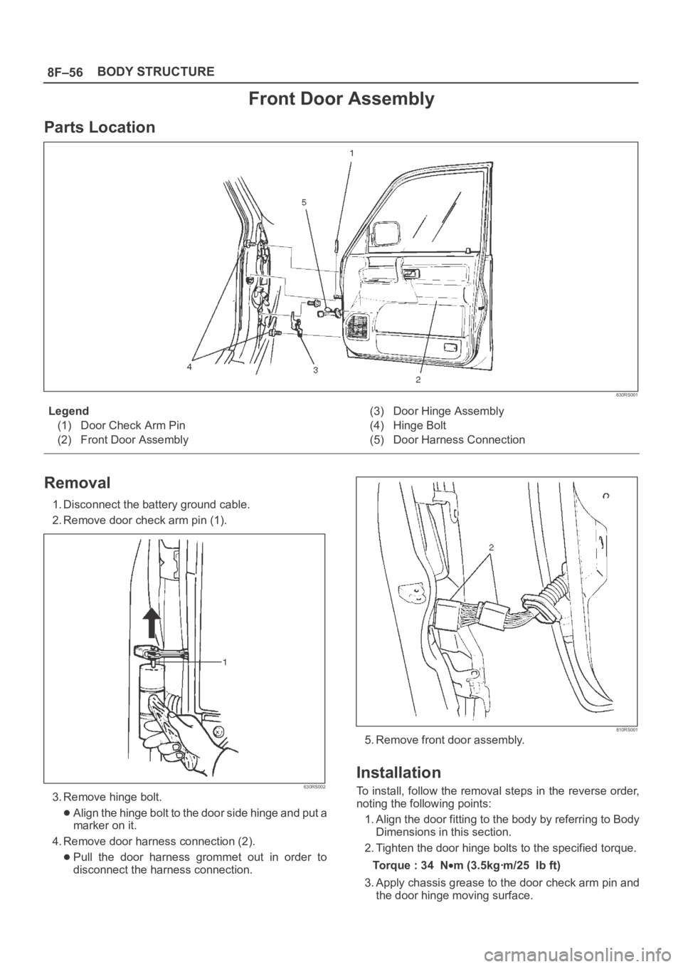
Parts Location
630RS001
Legend
(1) Door Check Arm Pin
(2) Front Door Assembly(3) Door Hinge Assembly
(4) Hinge Bolt
(5) Door Harness Connection
Removal
1. Disconnect the battery ground cable.
2. Remove door check arm pin (1).
630RS002
3. Remove hinge bolt.
Align the hinge bolt to the door side hinge and put a
marker on it.
4. Remove door harness connection (2).
Pull the door harness grommet out in order to
disconnect the harness connection.
810RS001
5. Remove front door assembly.
Installation
To install, follow the removal steps in the reverse order,
noting the following points:
1. Align the door fitting to the body by referring to Body
Dimensions in this section.
2. Tighten the door hinge bolts to the specified torque.
Torque : 34 N
m (3.5kgꞏm/25 lb ft)
3. Apply chassis grease to the door check arm pin and
the door hinge moving surface.
Page 3252 of 6000

8F–57 BODY STRUCTURE
Rear Door Assembly
Parts Location
650RW007
Legend
(1) Door Check Arm Pin
(2) Door Harness Connection(3) Rear Door Assembly
(4) Hinge Bolt
Removal
1. Disconnect the battery ground cable.
2. Apply a setting mark on the body side hinge.
3. Remove door check arm pin (1).
630RS002
4. Remove hinge bolt.
Open the front door and remove the body side hinge
bolts (2).
650RS002