stop start OPEL FRONTERA 1998 Manual Online
[x] Cancel search | Manufacturer: OPEL, Model Year: 1998, Model line: FRONTERA, Model: OPEL FRONTERA 1998Pages: 6000, PDF Size: 97 MB
Page 4649 of 6000
6D3–18STARTING AND CHARGING SYSTEM
Charging System
General Description
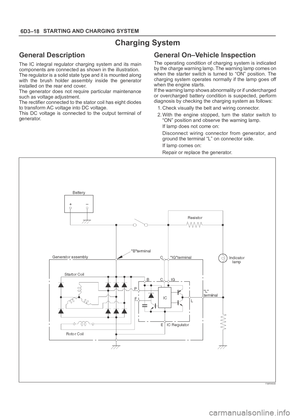
The IC integral regulator charging system and its main
components are connected as shown in the illustration.
The regulator is a solid state type and it is mounted along
with the brush holder assembly inside the generator
installed on the rear end cover.
The generator does not require particular maintenance
such as voltage adjustment.
The rectifier connected to the stator coil has eight diodes
to transform AC voltage into DC voltage.
This DC voltage is connected to the output terminal of
generator.
General On–Vehicle Inspection
The operating condition of charging system is indicated
by the charge warning lamp. The warning lamp comes on
when the starter switch is turned to “ON” position. The
charging system operates normally if the lamp goes off
when the engine starts.
If the warning lamp shows abnormality or if undercharged
or overcharged battery condition is suspected, perform
diagnosis by checking the charging system as follows:
1. Check visually the belt and wiring connector.
2. With the engine stopped, turn the stator switch to
“ON” position and observe the warning lamp.
If lamp does not come on:
Disconnect wiring connector from generator, and
ground the terminal “L” on connector side.
If lamp comes on:
Repair or replace the generator.
F06RW009
Page 4650 of 6000
6D3–19 STARTING AND CHARGING SYSTEM
Generator
Removal
1. Disconnect battery ground cable.
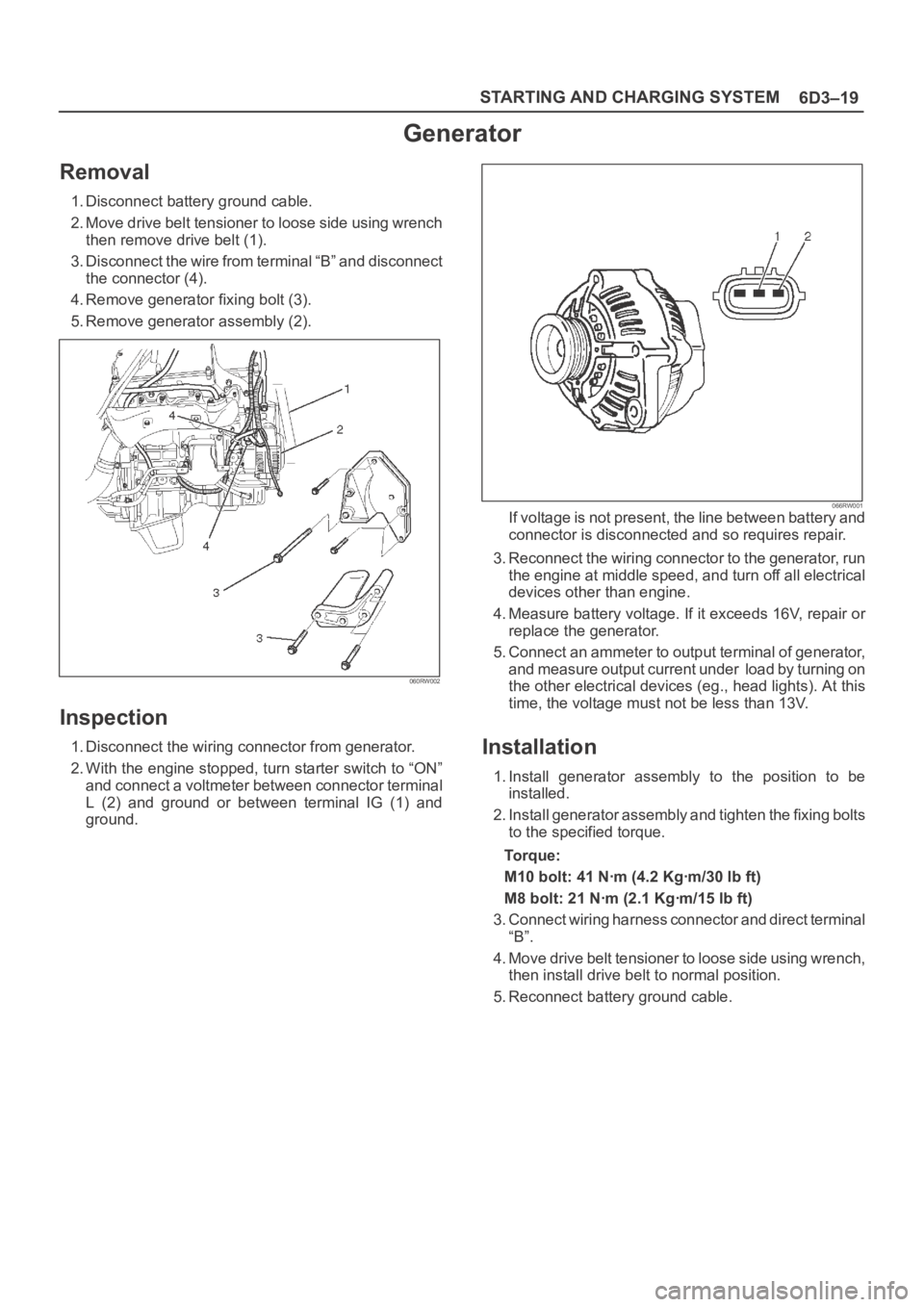
2. Move drive belt tensioner to loose side using wrench
then remove drive belt (1).
3. Disconnect the wire from terminal “B” and disconnect
the connector (4).
4. Remove generator fixing bolt (3).
5. Remove generator assembly (2).
060RW002
Inspection
1. Disconnect the wiring connector from generator.
2. With the engine stopped, turn starter switch to “ON”
and connect a voltmeter between connector terminal
L (2) and ground or between terminal IG (1) and
ground.
066RW001If voltage is not present, the line between battery and
connector is disconnected and so requires repair.
3. Reconnect the wiring connector to the generator, run
the engine at middle speed, and turn off all electrical
devices other than engine.
4. Measure battery voltage. If it exceeds 16V, repair or
replace the generator.
5. Connect an ammeter to output terminal of generator,
and measure output current under load by turning on
the other electrical devices (eg., head lights). At this
time, the voltage must not be less than 13V.
Installation
1. Install generator assembly to the position to be
installed.
2. Install generator assembly and tighten the fixing bolts
to the specified torque.
To r q u e :
M10 bolt: 41 Nꞏm (4.2 Kgꞏm/30 lb ft)
M8 bolt: 21 Nꞏm (2.1 Kgꞏm/15 lb ft)
3. Connect wiring harness connector and direct terminal
“B”.
4. Move drive belt tensioner to loose side using wrench,
then install drive belt to normal position.
5. Reconnect battery ground cable.
Page 4721 of 6000
6E–64
ENGINE DRIVEABILITY AND EMISSIONS
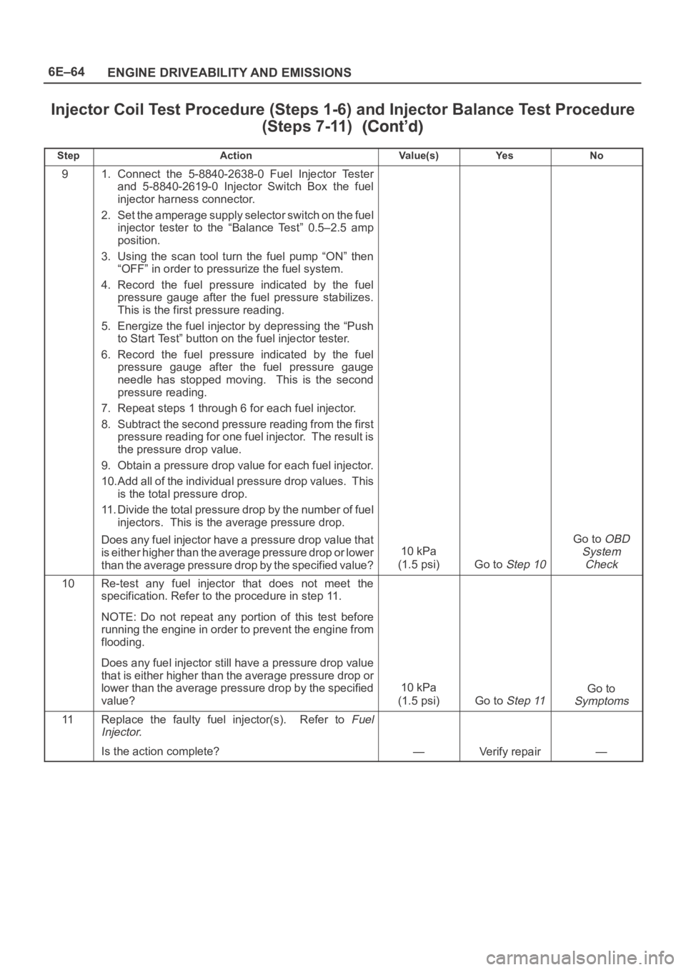
Injector Coil Test Procedure (Steps 1-6) and Injector Balance Test Procedure
(Steps 7-11)
StepNo Ye s Va l u e ( s ) Action
91. Connect the 5-8840-2638-0 Fuel Injector Tester
and 5-8840-2619-0 Injector Switch Box the fuel
injector harness connector.
2. Set the amperage supply selector switch on the fuel
injector tester to the “Balance Test” 0.5–2.5 amp
position.
3. Using the scan tool turn the fuel pump “ON” then
“OFF” in order to pressurize the fuel system.
4. Record the fuel pressure indicated by the fuel
pressure gauge after the fuel pressure stabilizes.
This is the first pressure reading.
5. Energize the fuel injector by depressing the “Push
to Start Test” button on the fuel injector tester.
6. Record the fuel pressure indicated by the fuel
pressure gauge after the fuel pressure gauge
needle has stopped moving. This is the second
pressure reading.
7. Repeat steps 1 through 6 for each fuel injector.
8. Subtract the second pressure reading from the first
pressure reading for one fuel injector. The result is
the pressure drop value.
9. Obtain a pressure drop value for each fuel injector.
10.Add all of the individual pressure drop values. This
is the total pressure drop.
11. Divide the total pressure drop by the number of fuel
injectors. This is the average pressure drop.
Does any fuel injector have a pressure drop value that
is either higher than the average pressure drop or lower
than the average pressure drop by the specified value?
10 kPa
(1.5 psi)
Go to Step 10
Go to OBD
System
Check
10Re-test any fuel injector that does not meet the
specification. Refer to the procedure in step 11.
NOTE: Do not repeat any portion of this test before
running the engine in order to prevent the engine from
flooding.
Does any fuel injector still have a pressure drop value
that is either higher than the average pressure drop or
lower than the average pressure drop by the specified
value?
10 kPa
(1.5 psi)
Go to Step 11
Go to
Symptoms
11Replace the faulty fuel injector(s). Refer to Fuel
Injector.
Is the action complete?—Verify repair—
Page 4725 of 6000
6E–68
ENGINE DRIVEABILITY AND EMISSIONS
Exhaust Gas Recirculation (EGR)
Diagnosis (For except EXPORT and
SOUTH AFRICA)
Pintle position error diagnosis is covered by DTC P0402,
P0404, P1404, P0405, P0406. If EGR diagnostic trouble
codes P0402, P0404, P1404, P0405, P0406 are
encountered, refer to the DTC charts.
Engine Tech 2 Data Definitions and
Ranges
A/C CLUTCH – Tech 2 Displays ON or OFF –
Indicates whether the PCM has commanded the A/C
clutch ON. Used in A/C system diagnostic.
A/C REQUEST — Tech 2 Displays YES or NO —
Indicates the state of the A/C request input circuit from the
HVAC controls. The PCM uses the A/C request signal to
determine whether A/C compressor operation is being
requested.
AIR/FUEL RATIO — Tech 2 Range 0.0-25.5 —
Air/fuel ratio indicates the PCM commanded value. In
closed loop, the air/fuel ratio should normally be
displayed around “14.2-14.7.” A lower air/fuel ratio
indicates a richer commanded mixture, which may be
seen during power enrichment or TWC protection modes.
A higher air/fuel ratio indicates a leaner commanded
mixture. This can be seen during deceleration fuel mode.
BAROMETRIC PRESSURE — Tech 2 Range 10-105
kPa/0.00-5.00 Volts —
The barometric pressure reading is determined from the
MAP sensor signal monitored during key up and wide
open throttle (WOT) conditions. The barometric pressure
is used to compensate for altitude differences and is
normally displayed around “61-104” depending on
altitude and barometric pressure.
CHECK TRANS LAMP — AUTO TRANSMISSION —
Indicates the need to check for a DTC with the Tech 2
when the lamp is flashing 0.2 seconds ON and 0.2
seconds OFF.
CMP ACT. COUNTER – Cam Position Activity
DECEL FUEL MODE — Tech 2 Display ACTIVE or
INACTIVE —
“ACTIVE” displayed indicates that the PCM has detected
conditions appropriate to operate in deceleration fuel
mode. The PCM will command the deceleration fuel
mode when it detects a closed throttle position while the
vehicle is traveling over 20 mph. While in the deceleration
fuel delivered by entering open loop and decreasing the
injector pulse width.
DESIRED EGR POS. — Tech 2 Range 0%-100% —
Represents the EGR pintle position that the PCM is
commanding.
DESIRED IDLE — Tech 2 Range 0-3187 RPM —
The idle speed that the PCM is commanding. The PCM
will compensate for various engine loads based on engine
coolant temperature, to keep the engine at the desired
speed.ECT — (Engine Coolant Temperature) Tech 2
Range –40
C to 151C (–40F to 304F) —
The engine coolant temperature (ECT) is mounted in the
coolant stream and sends engine temperature
information to the PCM. The PCM applies 5 volts to the
ECT sensor circuit. The sensor is a thermistor which
changes internal resistance as temperature changes.
When the sensor is cold (high resistance), the PCM
monitors a high signal voltage and interprets that as a cold
engine. As the sensor warms (decreasing resistance),
the voltage signal will decrease and the PCM will interpret
the lower voltage as a warm engine.
EGR DUTY CYCLE — Tech 2 Range 0%-100% —
Represents the EGR valve driver PWM signal from the
PCM. A duty cycle of 0% indicates that no EGR flow is
being commanded; a 100% duty cycle indicates
maximum EGR flow commanded.
EGR FEEDBACK — Tech 2 Range 0.00-5.00 Volts —
Indicates the EGR pintle position sensor signal voltage
being monitored by the PCM. A low voltage indicates a
fully extended pintle (closed valve); a voltage near 5 volts
indicates a retracted pintle (open valve).
ENGINE LOAD — Tech 2 Range 0%-100% —
Engine load is calculated by the PCM from engine speed
and MAF sensor readings. Engine load should increase
with an increase in RPM or air flow.
ENGINE RUN TIME — Tech 2 Range
00:00:00-99:99:99 Hrs:Min:Sec —
Indicates the time elapsed since the engine was started.
If the engine is stopped, engine run time will be reset to
00:00:00.
ENGINE SPEED — Range 0-9999 RPM —
Engine speed is computed by the PCM from the 58X
reference input. It should remain close to desired idle
under various engine loads with engine idling.
FUEL PUMP — Tech 2 Displays ON or OFF —
Indicates the PCM commanded state of the fuel pump
relay driver circuit.
FUEL TRIM CELL — Tech 2 Range 0-21 —
The fuel trim cell is dependent upon engine speed and
MAF sensor readings. A plot of RPM vs. MAF is divided
into 22 cells. Fuel trim cell indicates which cell is currently
active.
FUEL TRIM LEARN — Tech 2 Displays NO or YES
—
When conditions are appropriate for enabling long term
fuel trim corrections, fuel trim learn will display “YES.”
This indicates that the long term fuel trim is responding to
the short term fuel trim. If the fuel trim learn displays
“NO,” then long term fuel trim will not respond to changes
in short term fuel trim.
HO2S BANK 1, SEN. 1 — Tech 2 Range 0-1132 mV
—
Represents the fuel control exhaust oxygen sensor
output voltage. Should fluctuate constantly within a range
between 10 mV (lean exhaust) and 1000 mV (rich
exhaust) while operating in closed loop.
Page 4731 of 6000
6E–74
ENGINE DRIVEABILITY AND EMISSIONS
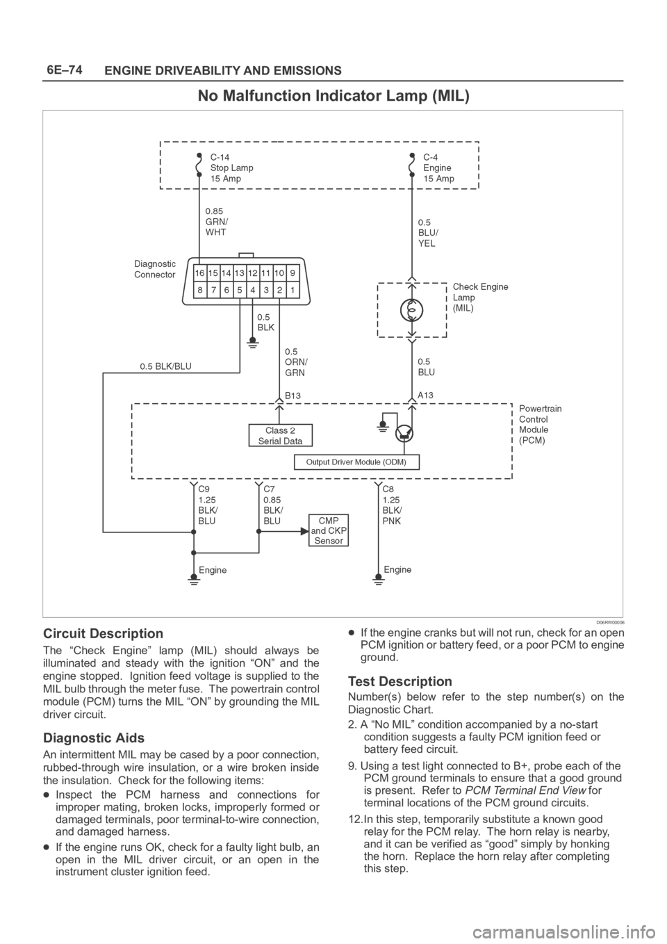
No Malfunction Indicator Lamp (MIL)
D06RW00006
Circuit Description
The “Check Engine” lamp (MIL) should always be
illuminated and steady with the ignition “ON” and the
engine stopped. Ignition feed voltage is supplied to the
MIL bulb through the meter fuse. The powertrain control
module (PCM) turns the MIL “ON” by grounding the MIL
driver circuit.
Diagnostic Aids
An intermittent MIL may be cased by a poor connection,
rubbed-through wire insulation, or a wire broken inside
the insulation. Check for the following items:
Inspect the PCM harness and connections for
improper mating, broken locks, improperly formed or
damaged terminals, poor terminal-to-wire connection,
and damaged harness.
If the engine runs OK, check for a faulty light bulb, an
open in the MIL driver circuit, or an open in the
instrument cluster ignition feed.
If the engine cranks but will not run, check for an open
PCM ignition or battery feed, or a poor PCM to engine
ground.
Test Description
Number(s) below refer to the step number(s) on the
Diagnostic Chart.
2. A “No MIL” condition accompanied by a no-start
condition suggests a faulty PCM ignition feed or
battery feed circuit.
9. Using a test light connected to B+, probe each of the
PCM ground terminals to ensure that a good ground
is present. Refer to
PCM Terminal End View for
terminal locations of the PCM ground circuits.
12.In this step, temporarily substitute a known good
relay for the PCM relay. The horn relay is nearby,
and it can be verified as “good” simply by honking
the horn. Replace the horn relay after completing
this step.
Page 4746 of 6000
6E–89 ENGINE DRIVEABILITY AND EMISSIONS
The valve or valve seat within the fuel pressure
regulator.
The fuel injector(s).
4. Fuel pressure that drops off during acceleration,
cruise, or hard cornering may case a lean condition.
A lean condition can cause a loss of power, surging,
or misfire. A lean condition can be diagnosed using
a Tech II Tech 2. If an extremely lean condition
occurs, the oxygen sensor(s) will stop toggling. The
oxygen sensor output voltage(s) will drop below 500
mV. Also, the fuel injector pulse width will increase.
IMPORTANT:Make sure the fuel system is not
operating in the “Fuel Cut-Off Mode.”
When the engine is at idle, the manifold pressure is
low (high vacuum). This low pressure (high vacuum)
is applied to the fuel pressure regulator diaphragm.
The low pressure (high vacuum) will offset the
pressure being applied to the fuel pressure regulator
diaphragm by the spring inside the fuel pressure
regulator. When this happens, the result is lower fuel
pressure. The fuel pressure at idle will vary slightly as
the barometric pressure changes, but the fuel
pressure at idle should always be less than the fuel
pressure noted in step 2 with the engine “OFF.”
16.Check the spark plug associated with a particular
fuel injector for fouling or saturation in order to
determine if that particular fuel injector is leaking. If
checking the spark plug associated with a particular
fuel injector for fouling or saturation does not
determine that a particular fuel injector is leaking,
use the following procedure:
Remove the fuel rail, but leave the fuel lines and
injectors connected to the fuel rail. Refer to
Fuel Rail
Assembly
in On-Vehicle Service.
Lift the fuel rail just enough to leave the fuel injector
nozzles in the fuel injector ports.
CAUTION: In order to reduce the risk of fire and
personal injury that may result from fuel spraying on
the engine, verify that the fuel rail is positioned over
the fuel injector ports and verify that the fuel injector
retaining clips are intact.
Pressurize the fuel system by connecting a 10 amp
fused jumper between B+ and the fuel pump relay
connector.
Visually and physically inspect the fuel injector
nozzles for leaks.
17.A rich condition may result from the fuel pressure
being above 376 kPa (55 psi). A rich condition may
cause a DTC P0132 or a DTC P0172 to set.
Driveability conditions associated with rich
conditions can include hard starting (followed by
black smoke) and a strong sulfur smell in the
exhaust.20.This test determines if the high fuel pressure is due
to a restricted fuel return line or if the high fuel
pressure is due to a faulty fuel pressure regulator.
21.A lean condition may result from fuel pressure
below 333 kPa (48 psi). A lean condition may
cause a DTC P0131 or a DTC P0171 to set.
Driveability conditions associated with lean
conditions can include hard starting (when the
engine is cold ), hesitation, poor driveability, lack of
power, surging , and misfiring.
22.Restricting the fuel return line causes the fuel
pressure to rise above the regulated fuel pressure.
Command the fuel pump “ON” with Tech 2. The fuel
pressure should rise above 376 kPa (55 psi) as the
fuel return line becomes partially closed.
NOTE: Do not allow the fuel pressure to exceed 414 kPa
( 6 0 p s i ) . F u e l p r e s s u r e i n e x c e s s o f 4 1 4 k P a ( 6 0 p s i ) m a y
damage the fuel pressure regulator.
CAUTION: To reduce the risk of fire and personal
injury:
It is necessary to relieve fuel system pressure
before connecting a fuel pressure gauge. Refer to
Fuel Pressure Relief Procedure, below.
A small amount of fuel may be released when
disconnecting the fuel lines. Cover fuel line
fittings with a shop towel before disconnecting, to
catch any fuel that may leak out. Place the towel in
an approved container when the disconnect is
completed.
Fuel Pressure Relief Procedure
1. Remove the fuel cap.
2. Remove the fuel pump relay from the underhood
relay center.
3. Start the engine and allow it to stall.
4. Crank the engine for an additional 3 seconds.
Fuel Gauge Installation
1. Remove the shoulder fitting cap.
2. Install fuel gauge 5-8840-0378-0 to the fuel feed line
located in front of and above the right side valve train
cover.
3. Reinstall the fuel pump relay.
Page 4747 of 6000
6E–90
ENGINE DRIVEABILITY AND EMISSIONS
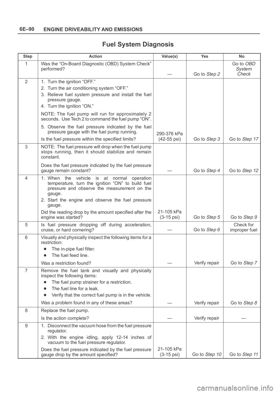
Fuel System Diagnosis
StepActionVa l u e ( s )Ye sNo
1Was the “On-Board Diagnostic (OBD) System Check”
performed?
—Go to Step 2
Go to OBD
System
Check
21. Turn the ignition “OFF.”
2. Turn the air conditioning system “OFF.”
3. Relieve fuel system pressure and install the fuel
pressure gauge.
4. Turn the ignition “ON.”
NOTE: The fuel pump will run for approximately 2
seconds. Use Tech 2 to command the fuel pump “ON”.
5. Observe the fuel pressure indicated by the fuel
pressure gauge with the fuel pump running.
Is the fuel pressure within the specified limits?
290-376 kPa
(42-55 psi)
Go to Step 3Go to Step 17
3NOTE: The fuel pressure will drop when the fuel pump
stops running, then it should stabilize and remain
constant.
Does the fuel pressure indicated by the fuel pressure
gauge remain constant?
—Go to Step 4Go to Step 12
41. When the vehicle is at normal operation
temperature, turn the ignition “ON” to build fuel
pressure and observe the measurement on the
gauge.
2. Start the engine and observe the fuel pressure
gauge.
Did the reading drop by the amount specified after the
engine was started?
21-105 kPa
(3-15 psi)
Go to Step 5Go to Step 9
5Is fuel pressure dropping off during acceleration,
cruise, or hard cornering?
—Go to Step 6
Check for
improper fuel
6Visually and physically inspect the following items for a
restriction:
The in-pipe fuel filter.
The fuel feed line.
Was a restriction found?
—Verify repairGo to Step 7
7Remove the fuel tank and visually and physically
inspect the following items:
The fuel pump strainer for a restriction.
The fuel line for a leak.
Verify that the correct fuel pump is in the vehicle.
Was a problem found in any of these areas?
—Verify repairGo to Step 8
8Replace the fuel pump.
Is the action complete?
—Verify repair—
91. Disconnect the vacuum hose from the fuel pressure
regulator.
2. With the engine idling, apply 12-14 inches of
vacuum to the fuel pressure regulator.
Does the fuel pressure indicated by the fuel pressure
gauge drop by the amount specified?
21-105 kPa
(3-15 psi)
Go to Step 10Go to Step 11
Page 4750 of 6000
6E–93 ENGINE DRIVEABILITY AND EMISSIONS
Idle Air Control (IAC) System Check
Circuit Description
The powertrain control module (PCM) controls engine
idle speed with the idle air control (IAC) valve. To increase
idle speed, the PCM retracts the IAC valve pintle away
from its seat, allowing more air to bypass the throttle bore.
To decrease idle speed, it extends the IAC valve pintle
towards its seat, reducing by pass air flow. Tech 2 will
read the PCM commands to the IAC valve in counts.
Higher counts indicate more air bypass (higher idle).
Lower counts indicate less air is allowed to bypass (lower
idle).
Diagnostic Aids
A slow, unstable, or fast idle may be caused by a non-IAC
system problem that cannot be overcome by the IAC
valve. Out of control range IAC Tech 2 counts will be
above 60 if idle is too low, and zero counts if idle is too
high. The following checks should be made to repair a
non-IAC system problem:
Vacuum leak (high idle) – If idle is too high, stop the
engine. Fully extend (low) IAC with the Tech 2. Start
the engine. If idle speed is above 800 RPM, locate and
correct the vacuum leak, including the PCV system.
Check for binding of the throttle blade or linkage.
Lean heated oxygen sensor signal (high air/fuel ratio) –
The idle speed may be too high or too low. Engine
speed may vary up and down, and disconnecting the
IAC valve does not help. Diagnostic trouble codes
P0131, P0151, P0171, or P0174 may be set. Tech 2
oxygen (O2) voltage will be less than 100 mV (0.1 V).
Check for low regulated fuel pressure, water in fuel, or
a restricted injector.
Rich heated oxygen sensor signal (low air/fuel ratio) –
The idle speed will be too low. Tech 2 IAC counts will
usually be above 80. The system is obviously rich and
may exhibit black smoke in the exhaust.
Tech 2 O2 voltage will be fixed at about 750 mV (0.75
V). Check for high fuel pressure, or a leaking or
sticking injector. A silicon-contaminated heated
oxygen sensor will show an O2 voltage slow to
respond on Tech 2.
Throttle body – Remove the IAC valve and inspect the
bore for foreign material.
IAC valve electrical connections – IAC valve
connections should be carefully checked for proper
contact.
PCV valve – An incorrect or faulty PCV valve may
result in an incorrect idle speed. Refer to
Diagnosis,
Rough Idle, Stalling.
If intermittent poor driveability or
idle symptoms are resolved by disconnecting the IAC,
carefully recheck the connections and valve terminal
resistance, or replace the IAC.
Test Description
Number(s) below refer to the step number(s) on the
Diagnostic Chart.
1. The Tech 2 is used to extend and retract the IAC
valve. Valve movement is verified by an engine
speed change. If no change in engine speed
occurs, the valve can be resettled when removed
from the throttle body.
2. This step checks the quality of the IAC movement in
step 1. Between 700 revolutions per minute (RPM)
and about 1500 RPM, the engine speed should
change smoothly with each flash of the tester light
in both extend and retract. If the IAC valve is
retracted beyond the control range (about 1500
RPM), it may take many flashes to extend the IAC
valve before engine speed will begin to drop. This
is normal on certain engines. Fully extending the
IAC may cause engine stall. This may be normal.
Page 4909 of 6000
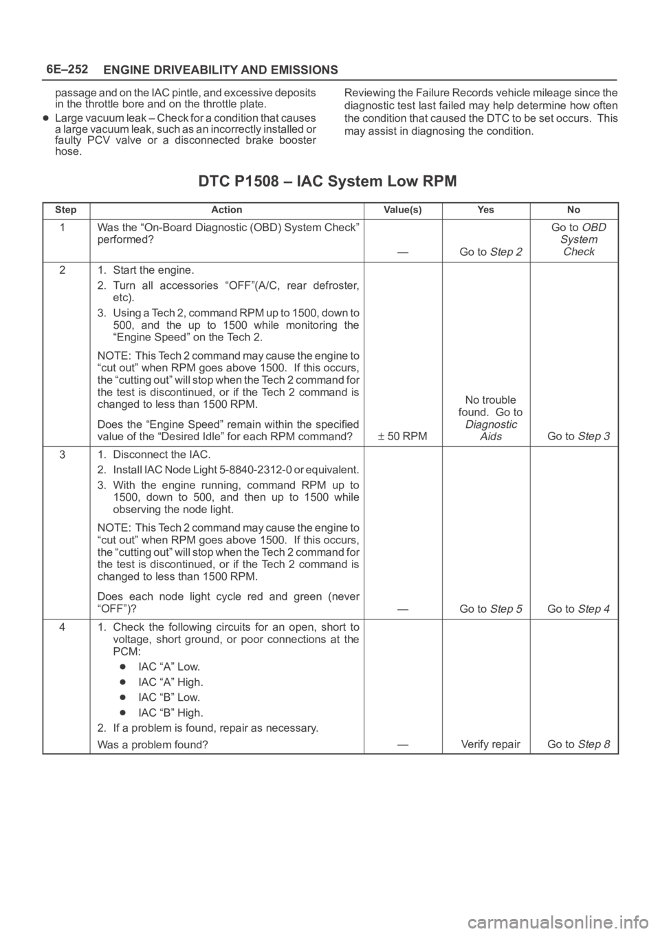
6E–252
ENGINE DRIVEABILITY AND EMISSIONS
passage and on the IAC pintle, and excessive deposits
in the throttle bore and on the throttle plate.
Large vacuum leak – Check for a condition that causes
a large vacuum leak, such as an incorrectly installed or
faulty PCV valve or a disconnected brake booster
hose.Reviewing the Failure Records vehicle mileage since the
diagnostic test last failed may help determine how often
the condition that caused the DTC to be set occurs. This
may assist in diagnosing the condition.
DTC P1508 – IAC System Low RPM
StepActionVa l u e ( s )Ye sNo
1Was the “On-Board Diagnostic (OBD) System Check”
performed?
—Go to Step 2
Go to OBD
System
Check
21. Start the engine.
2. Turn all accessories “OFF”(A/C, rear defroster,
etc).
3. Using a Tech 2, command RPM up to 1500, down to
500, and the up to 1500 while monitoring the
“Engine Speed” on the Tech 2.
NOTE: This Tech 2 command may cause the engine to
“cut out” when RPM goes above 1500. If this occurs,
the “cutting out” will stop when the Tech 2 command for
the test is discontinued, or if the Tech 2 command is
changed to less than 1500 RPM.
Does the “Engine Speed” remain within the specified
value of the “Desired Idle” for each RPM command?
50 RPM
No trouble
found. Go to
Diagnostic
Aids
Go to Step 3
31. Disconnect the IAC.
2. Install IAC Node Light 5-8840-2312-0 or equivalent.
3. With the engine running, command RPM up to
1500, down to 500, and then up to 1500 while
observing the node light.
NOTE: This Tech 2 command may cause the engine to
“cut out” when RPM goes above 1500. If this occurs,
the “cutting out” will stop when the Tech 2 command for
the test is discontinued, or if the Tech 2 command is
changed to less than 1500 RPM.
Does each node light cycle red and green (never
“OFF”)?
—Go to Step 5Go to Step 4
41. Check the following circuits for an open, short to
voltage, short ground, or poor connections at the
PCM:
IAC “A” Low.
IAC “A” High.
IAC “B” Low.
IAC “B” High.
2. If a problem is found, repair as necessary.
Was a problem found?
—Verify repairGo to Step 8
Page 4912 of 6000
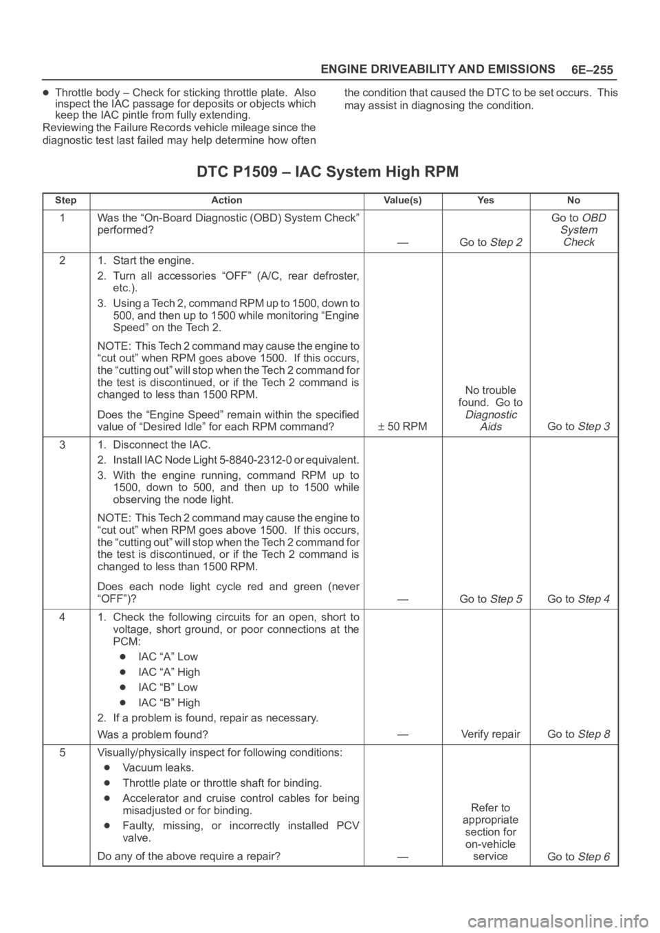
6E–255 ENGINE DRIVEABILITY AND EMISSIONS
Throttle body – Check for sticking throttle plate. Also
inspect the IAC passage for deposits or objects which
keep the IAC pintle from fully extending.
Reviewing the Failure Records vehicle mileage since the
diagnostic test last failed may help determine how oftenthe condition that caused the DTC to be set occurs. This
may assist in diagnosing the condition.
DTC P1509 – IAC System High RPM
StepActionVa l u e ( s )Ye sNo
1Was the “On-Board Diagnostic (OBD) System Check”
performed?
—Go to Step 2
Go to OBD
System
Check
21. Start the engine.
2. Turn all accessories “OFF” (A/C, rear defroster,
etc.).
3. Using a Tech 2, command RPM up to 1500, down to
500, and then up to 1500 while monitoring “Engine
Speed” on the Tech 2.
NOTE: This Tech 2 command may cause the engine to
“cut out” when RPM goes above 1500. If this occurs,
the “cutting out” will stop when the Tech 2 command for
the test is discontinued, or if the Tech 2 command is
changed to less than 1500 RPM.
Does the “Engine Speed” remain within the specified
value of “Desired Idle” for each RPM command?
50 RPM
No trouble
found. Go to
Diagnostic
Aids
Go to Step 3
31. Disconnect the IAC.
2. Install IAC Node Light 5-8840-2312-0 or equivalent.
3. With the engine running, command RPM up to
1500, down to 500, and then up to 1500 while
observing the node light.
NOTE: This Tech 2 command may cause the engine to
“cut out” when RPM goes above 1500. If this occurs,
the “cutting out” will stop when the Tech 2 command for
the test is discontinued, or if the Tech 2 command is
changed to less than 1500 RPM.
Does each node light cycle red and green (never
“OFF”)?
—Go to Step 5Go to Step 4
41. Check the following circuits for an open, short to
voltage, short ground, or poor connections at the
PCM:
IAC “A” Low
IAC “A” High
IAC “B” Low
IAC “B” High
2. If a problem is found, repair as necessary.
Was a problem found?
—Verify repairGo to Step 8
5Visually/physically inspect for following conditions:
Vacuum leaks.
Throttle plate or throttle shaft for binding.
Accelerator and cruise control cables for being
misadjusted or for binding.
Faulty, missing, or incorrectly installed PCV
valve.
Do any of the above require a repair?
—
Refer to
appropriate
section for
on-vehicle
service
Go to Step 6