stop start OPEL FRONTERA 1998 Repair Manual
[x] Cancel search | Manufacturer: OPEL, Model Year: 1998, Model line: FRONTERA, Model: OPEL FRONTERA 1998Pages: 6000, PDF Size: 97 MB
Page 4049 of 6000
4B1–4
DRIVE LINE CONTROL SYSTEM (SHIFT ON THE FLY)
Inspection and Repair
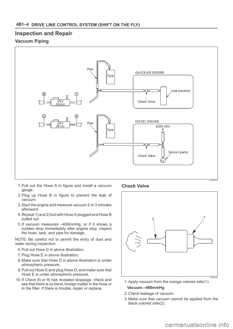
Va c u u m P i p i n g
C04RW016
1. Pull out the Hose A in figure and install a vacuum
gauge.
2. Plug up Hose B in figure to prevent the leak of
vacuum.
3. Start the engine and measure vacuum 2 or 3 minutes
afterward.
4. Repeat 1) and 2) but with Hose A plugged and Hose B
pulled out.
5. If vacuum measures –400mmHg, or if it shows a
sudden drop immediately after engine stop, inspect
the hose, tank, and pipe for damage.
NOTE: Be careful not to permit the entry of dust and
water during inspection.
6. Pull out Hose D in above illustration.
7. Plug Hose E in above illustration.
8. Make sure that Hose D in above illustration is under
atmospheric pressure.
9. Pull out Hose E and plug Hose D, and make sure that
Hose E is under atmospheric pressure.
10. If Check 8) or 9) has revealed stoppage, check and
see that there is no bend, foreign matter in the hose or
in the filter. If there is trouble, repair or replace.Check Valve
C04RS004
1. Apply vacuum from the orange colored side(1).
Vacuum:–400mmHg
2. Check leakage of vacuum.
3. Make sure that vacuum cannot be applied from the
black colored side(2).
Page 4054 of 6000
4B1–9 DRIVE LINE CONTROL SYSTEM (SHIFT ON THE FLY)
Retrial
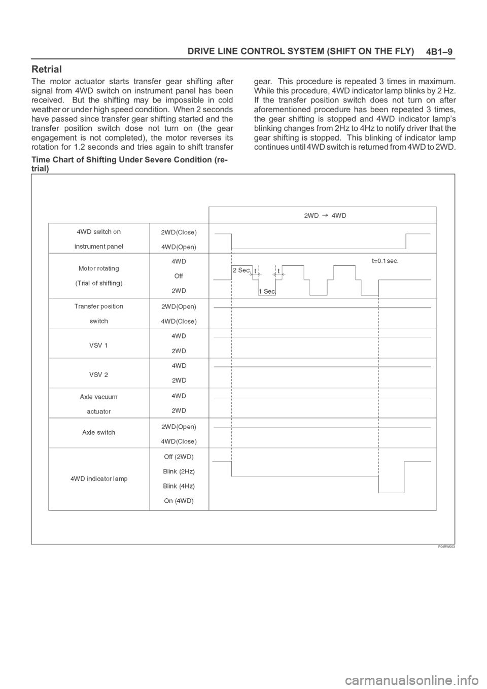
The motor actuator starts transfer gear shifting after
signal from 4WD switch on instrument panel has been
received. But the shifting may be impossible in cold
weather or under high speed condition. When 2 seconds
have passed since transfer gear shifting started and the
transfer position switch dose not turn on (the gear
engagement is not completed), the motor reverses its
rotation for 1.2 seconds and tries again to shift transfergear. This procedure is repeated 3 times in maximum.
While this procedure, 4WD indicator lamp blinks by 2 Hz.
If the transfer position switch does not turn on after
aforementioned procedure has been repeated 3 times,
the gear shifting is stopped and 4WD indicator lamp’s
blinking changes from 2Hz to 4Hz to notify driver that the
gear shifting is stopped. This blinking of indicator lamp
continues until 4WD switch is returned from 4WD to 2WD.
Time Chart of Shifting Under Severe Condition (re-
trial)
F04RW003
Page 4056 of 6000
4B1–11 DRIVE LINE CONTROL SYSTEM (SHIFT ON THE FLY)
Functions of Indicator Lamp
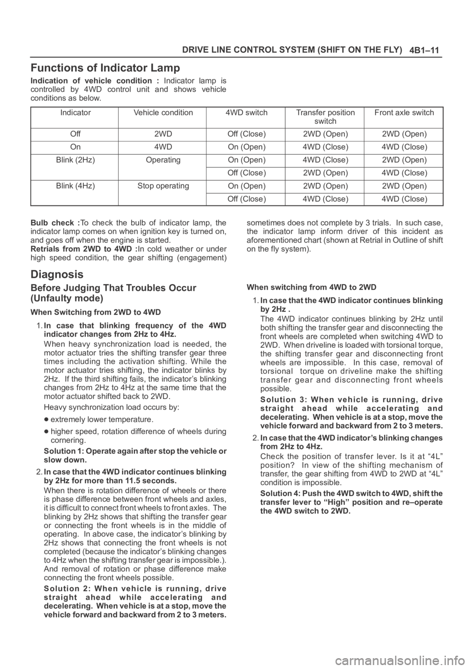
Indication of vehicle condition : Indicator lamp is
controlled by 4WD control unit and shows vehicle
conditions as below.
Indicator
Vehicle condition4WD switchTransfer position
switchFront axle switch
Off2WDOff (Close)2WD (Open)2WD (Open)
On4WDOn (Open)4WD (Close)4WD (Close)
Blink (2Hz)OperatingOn (Open)4WD (Close)2WD (Open)
Off (Close)2WD (Open)4WD (Close)
Blink (4Hz)Stop operatingOn (Open)2WD (Open)2WD (Open)
Off (Close)4WD (Close)4WD (Close)
Bulb check :To check the bulb of indicator lamp, the
indicator lamp comes on when ignition key is turned on,
and goes off when the engine is started.
Retrials from 2WD to 4WD :In cold weather or under
high speed condition, the gear shifting (engagement)sometimes does not complete by 3 trials. In such case,
the indicator lamp inform driver of this incident as
aforementioned chart (shown at Retrial in Outline of shift
on the fly system).
Diagnosis
Before Judging That Troubles Occur
(Unfaulty mode)
When Switching from 2WD to 4WD
1.In case that blinking frequency of the 4WD
indicator changes from 2Hz to 4Hz.
When heavy synchronization load is needed, the
motor actuator tries the shifting transfer gear three
times including the activation shifting. While the
motor actuator tries shifting, the indicator blinks by
2Hz. If the third shifting fails, the indicator’s blinking
changes from 2Hz to 4Hz at the same time that the
motor actuator shifted back to 2WD.
Heavy synchronization load occurs by:
extremely lower temperature.
higher speed, rotation difference of wheels during
cornering.
Solution 1: Operate again after stop the vehicle or
slow down.
2.In case that the 4WD indicator continues blinking
by 2Hz for more than 11.5 seconds.
When there is rotation difference of wheels or there
is phase difference between front wheels and axles,
it is difficult to connect front wheels to front axles. The
blinking by 2Hz shows that shifting the transfer gear
or connecting the front wheels is in the middle of
operating. In above case, the indicator’s blinking by
2Hz shows that connecting the front wheels is not
completed (because the indicator’s blinking changes
to 4Hz when the shifting transfer gear is impossible.).
And removal of rotation or phase difference make
connecting the front wheels possible.
Solution 2: When vehicle is running, drive
straight ahead while accelerating and
decelerating. When vehicle is at a stop, move the
vehicle forward and backward from 2 to 3 meters.When switching from 4WD to 2WD
1.In case that the 4WD indicator continues blinking
by 2Hz .
The 4WD indicator continues blinking by 2Hz until
both shifting the transfer gear and disconnecting the
front wheels are completed when switching 4WD to
2WD. When driveline is loaded with torsional torque,
the shifting transfer gear and disconnecting front
wheels are impossible. In this case, removal of
torsional torque on driveline make the shifting
transfer gear and disconnecting front wheels
possible.
Solution 3: When vehicle is running, drive
straight ahead while accelerating and
decelerating. When vehicle is at a stop, move the
vehicle forward and backward from 2 to 3 meters.
2.In case that the 4WD indicator’s blinking changes
from 2Hz to 4Hz.
Check the position of transfer lever. Is it at “4L”
position? In view of the shifting mechanism of
transfer, the gear shifting from 4WD to 2WD at “4L”
condition is impossible.
Solution 4: Push the 4WD switch to 4WD, shift the
transfer lever to “High” position and re–operate
the 4WD switch to 2WD.
Page 4078 of 6000
4B1–33 DRIVE LINE CONTROL SYSTEM (SHIFT ON THE FLY)
Inspection and Repair
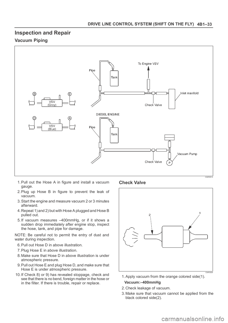
Va c u u m P i p i n g
C04RW014
1. Pull out the Hose A in figure and install a vacuum
gauge.
2. Plug up Hose B in figure to prevent the leak of
vacuum.
3. Start the engine and measure vacuum 2 or 3 minutes
afterward.
4. Repeat 1) and 2) but with Hose A plugged and Hose B
pulled out.
5. If vacuum measures –400mmHg, or if it shows a
sudden drop immediately after engine stop, inspect
the hose, tank, and pipe for damage.
NOTE: Be careful not to permit the entry of dust and
water during inspection.
6. Pull out Hose D in above illustration.
7. Plug Hose E in above illustration.
8. Make sure that Hose D in above illustration is under
atmospheric pressure.
9. Pull out Hose E and plug Hose D, and make sure that
Hose E is under atmospheric pressure.
10. If Check 8) or 9) has revealed stoppage, check and
see that there is no bend, foreign matter in the hose or
in the filter. If there is trouble, repair or replace.Check Valve
C04RS004
1. Apply vacuum from the orange colored side(1).
Vacuum:–400mmHg
2. Check leakage of vacuum.
3. Make sure that vacuum cannot be applied from the
black colored side(2).
Page 4096 of 6000
4B2–13 DRIVE LINE CONTROL SYSTEM (TOD)
Diagnosis
General Information Diagnosis
The troubles on TOD are classified into the group that can
be identified by the lighting status of the TOD indicator
lamps and those that can be recognized as abnormal
phenomena of the vehicle by the driver.
The troubles that can be identified by the lighting status of
the TOD indicator lamps are examined by the procedures
“Diagnosis from Trouble Codes” and “Trouble Diagnosis
Depending on The Status of TOD indicator”. The troubles
that can be recognized as abnormal phenomena of the
vehicle by the driver are examined by the procedure
“Diagnosis from symptom”.
Self-diagnosis
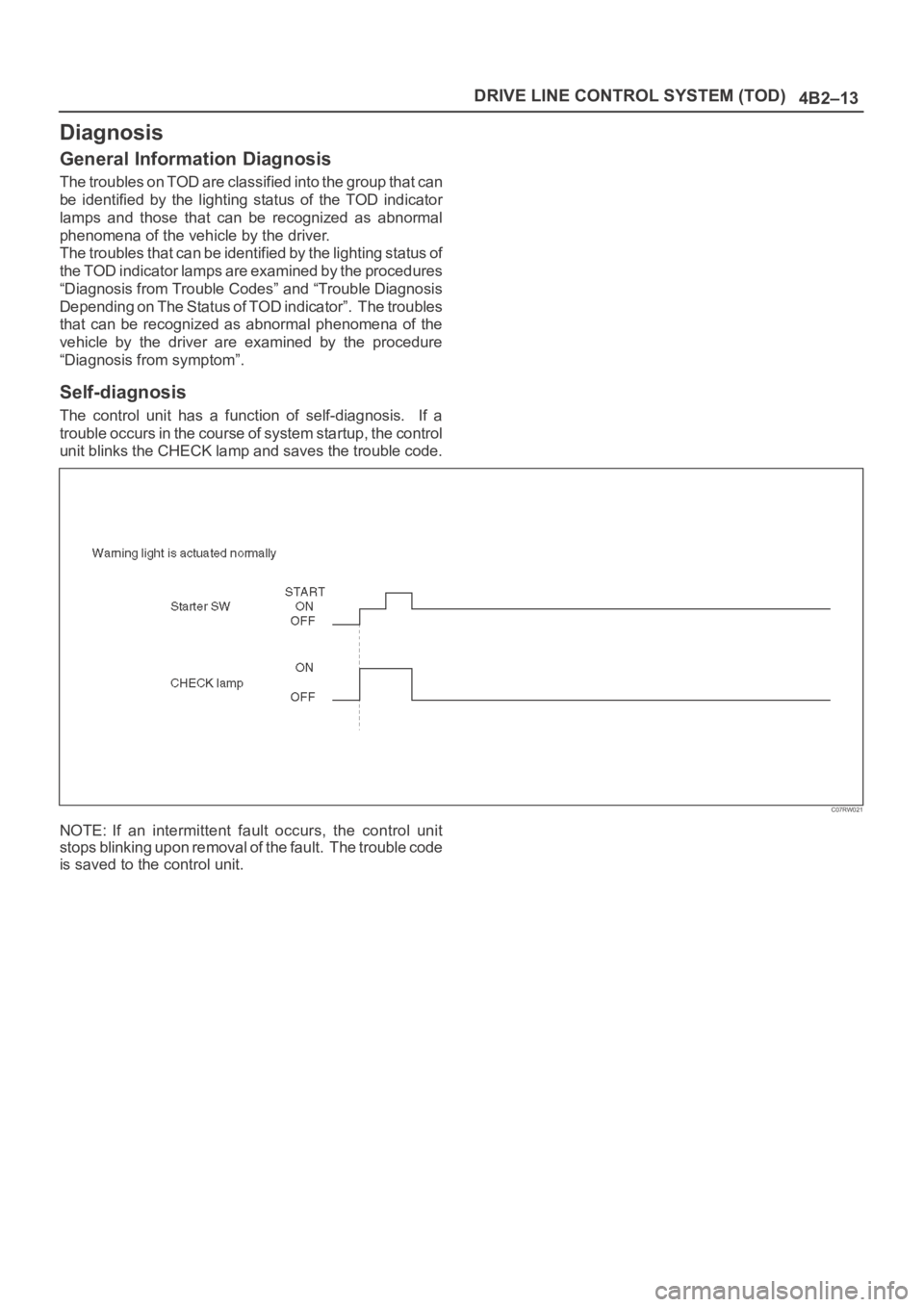
The control unit has a function of self-diagnosis. If a
trouble occurs in the course of system startup, the control
unit blinks the CHECK lamp and saves the trouble code.
C07RW021
NOTE: If an intermittent fault occurs, the control unit
stops blinking upon removal of the fault. The trouble code
is saved to the control unit.
Page 4098 of 6000
4B2–15 DRIVE LINE CONTROL SYSTEM (TOD)
How to Clear The Trouble Code
The trouble codes saved to the control unit can be deleted
by the following procedure if the starter switch is being in
the OFF position.
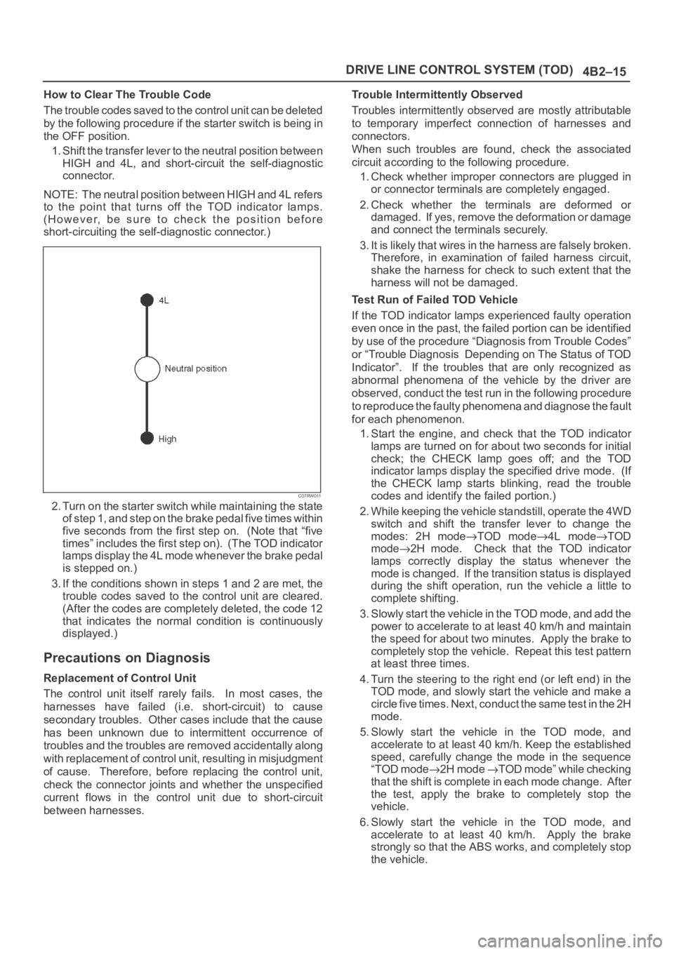
1. Shift the transfer lever to the neutral position between
HIGH and 4L, and short-circuit the self-diagnostic
connector.
NOTE: The neutral position between HIGH and 4L refers
to the point that turns off the TOD indicator lamps.
(However, be sure to check the position before
short-circuiting the self-diagnostic connector.)
C07RW011
2. Turn on the starter switch while maintaining the state
of step 1, and step on the brake pedal five times within
five seconds from the first step on. (Note that “five
times” includes the first step on). (The TOD indicator
lamps display the 4L mode whenever the brake pedal
is stepped on.)
3. If the conditions shown in steps 1 and 2 are met, the
trouble codes saved to the control unit are cleared.
(After the codes are completely deleted, the code 12
that indicates the normal condition is continuously
displayed.)
Precautions on Diagnosis
Replacement of Control Unit
The control unit itself rarely fails. In most cases, the
harnesses have failed (i.e. short-circuit) to cause
secondary troubles. Other cases include that the cause
has been unknown due to intermittent occurrence of
troubles and the troubles are removed accidentally along
with replacement of control unit, resulting in misjudgment
of cause. Therefore, before replacing the control unit,
check the connector joints and whether the unspecified
current flows in the control unit due to short-circuit
between harnesses.Trouble Intermittently Observed
Troubles intermittently observed are mostly attributable
to temporary imperfect connection of harnesses and
connectors.
When such troubles are found, check the associated
circuit according to the following procedure.
1. Check whether improper connectors are plugged in
or connector terminals are completely engaged.
2. Check whether the terminals are deformed or
damaged. If yes, remove the deformation or damage
and connect the terminals securely.
3. It is likely that wires in the harness are falsely broken.
Therefore, in examination of failed harness circuit,
shake the harness for check to such extent that the
harness will not be damaged.
Test Run of Failed TOD Vehicle
If the TOD indicator lamps experienced faulty operation
even once in the past, the failed portion can be identified
by use of the procedure “Diagnosis from Trouble Codes”
or “Trouble Diagnosis Depending on The Status of TOD
Indicator”. If the troubles that are only recognized as
abnormal phenomena of the vehicle by the driver are
observed, conduct the test run in the following procedure
to reproduce the faulty phenomena and diagnose the fault
for each phenomenon.
1. Start the engine, and check that the TOD indicator
lamps are turned on for about two seconds for initial
check; the CHECK lamp goes off; and the TOD
indicator lamps display the specified drive mode. (If
the CHECK lamp starts blinking, read the trouble
codes and identify the failed portion.)
2. While keeping the vehicle standstill, operate the 4WD
switch and shift the transfer lever to change the
modes: 2H mode
TOD mode4L modeTOD
mode
2H mode. Check that the TOD indicator
lamps correctly display the status whenever the
mode is changed. If the transition status is displayed
during the shift operation, run the vehicle a little to
complete shifting.
3. Slowly start the vehicle in the TOD mode, and add the
power to accelerate to at least 40 km/h and maintain
the speed for about two minutes. Apply the brake to
completely stop the vehicle. Repeat this test pattern
at least three times.
4. Turn the steering to the right end (or left end) in the
TOD mode, and slowly start the vehicle and make a
c i r c l e f i v e t i m e s . N e x t , c o n d u c t t h e s a m e t e s t i n t h e 2 H
mode.
5. Slowly start the vehicle in the TOD mode, and
accelerate to at least 40 km/h. Keep the established
speed, carefully change the mode in the sequence
“TOD mode
2H mode TOD mode” while checking
that the shift is complete in each mode change. After
the test, apply the brake to completely stop the
vehicle.
6. Slowly start the vehicle in the TOD mode, and
accelerate to at least 40 km/h. Apply the brake
strongly so that the ABS works, and completely stop
the vehicle.
Page 4099 of 6000
DRIVE LINE CONTROL SYSTEM (TOD) 4B2–16
7. Slowly start the vehicle in the 4L mode, and
accelerate to at least 20 km/h. Apply the brake to
completely stop the vehicle.
If the CHECK lamp starts blinking during the test run, read
the trouble codes and give appropriate maintenance
according to the diagnostic procedure. If the TOD
indicator lamps are lit abnormally during the run, check
the lighting condition and give appropriate maintenance
according to the diagnostic procedure. Even if the
phenomena are not observed, try to reproduce the
abnormal state reported by the customer to the possible
extent.
Post-Repair Check
As long as the starter is not turned off, the TOD indicator
lamps continue blinking even after the failed portion
repaired. Therefore, upon completion of repair, be sure to
turn off the starter switch once and then turn on it to
conduct the test run sequence specified in steps 1
through 7 above and check that the TOD indicator lamps
no longer show any faulty status.
Page 4122 of 6000
4B2–39 DRIVE LINE CONTROL SYSTEM (TOD)
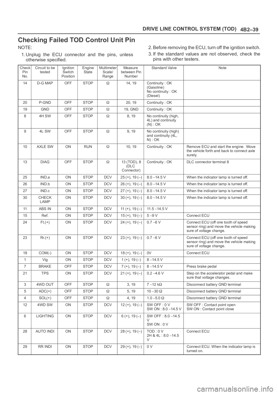
Checking Failed TOD Control Unit Pin
NOTE:
1. Unplug the ECU connector and the pins, unless
otherwise specified.2. Before removing the ECU, turn off the ignition switch.
3. If the standard values are not observed, check the
pins with other testers.
Check
Pin
No.Circuit to be
testedIgnition
Switch
PositionEngine
StateMultimeter
Scale/
RangeMeasure
between Pin
NumberStandard ValveNote
14D-G MAPOFFSTOP14, 19Continuity : OK
(Gasoline)
No continuity : OK
(Diesel)
20P-GNDOFFSTOP20, 19Continuity : OK
19GNDOFFSTOP19, GNDContinuity : OK
84H SWOFFSTOP8, 19No continuity (high,
4L) and continuity
(N) : OK
94L SWOFFSTOP9, 19No continuity (high)
and continuity (4L,
N) : OK
10AXLE SWONRUN10, 19Continuity : OKRemove ECU and start the engine. Move
the vehicle forth and back to connect axle
surely.
13DIAGOFFSTOP13 (TOD), 8
(DLC
Connector)Continuity : OKDLC connector terminal 8
25IND.aONSTOPDCV25 (+), 19 (–)8.0 14.5 VWhen the indicator lamp is turned off.
26IND.bONSTOPDCV26 (+), 19 (–)8.0 14.5 VWhen the indicator lamp is turned off.
27IND.cONSTOPDCV27 (+), 19 (–)8.0 14.5 VWhen the indicator lamp is turned off.
30CHECK
LAMPONSTOPDCV30 (+), 19 (–)8.0 14.5 VWhen the indicator lamp is turned off.
11ABS INONSTOPDCV11 (+), 19 (–)11 . 5 14.5 V
15Ref.ONSTOPDCV15 (+), 19 (–)5 9 VConnect ECU
24Ft.(+)ONSTOPDCV24 (+), 19 (–)0.7 6 VConnect ECU (off one tooth of speed
sensor ring) and move the vehicle making
sure of voltage change.
23Rr.(+)ONSTOPDCV23 (+), 19 (–)0.7 6 VConnect ECU (off one tooth of speed
sensor ring) and move the vehicle making
sure of voltage change.
18COM(-)ONSTOPDCV18 (+), 19 (–)0VConnect ECU
1VigONSTOPDCV1 (+), 19 (–)8 14.5 V
7BRAKEOFFSTOPDCV7 (+), 19 (–)8 14.5 VPress brake pedal
21TPSONSTOPDCV21 (+), 19 (–)0.2 4.6 VStep on the accelerator pedal and make
sure that voltage changes.
34WD OUTOFFSTOP3, 197 12 kDisconnect battery GND terminal
5ADC(+)OFFSTOP5, 1910 30 Disconnect battery GND terminal
4SOL(+)OFFSTOP4, 191.0 5.0 Disconnect battery GND terminal
124WD SWONSTOPDCV12 (+), 19 (–)SW OFF : 0 V
SW ON : 8.0 14.5 VSW OFF : Contact point open
SW ON : Contact point close
6LIGHTINGONSTOPDCV6 (+), 19 (–)SW OFF : 8.0 14.5
V
SW ON : 0 V
28AUTO INDIONSTOPDCV28 (+), 19 (–)TOD : 0 V
2H & 4L : 8.0 14.5
VConnect ECU
29RR INDIONSTOPDCV29 (+), 19 (–)0 VConnect ECU. When the indicator lamp is
turned on.
Page 4320 of 6000
4D2–13 TRANSFER CASE (TOD)
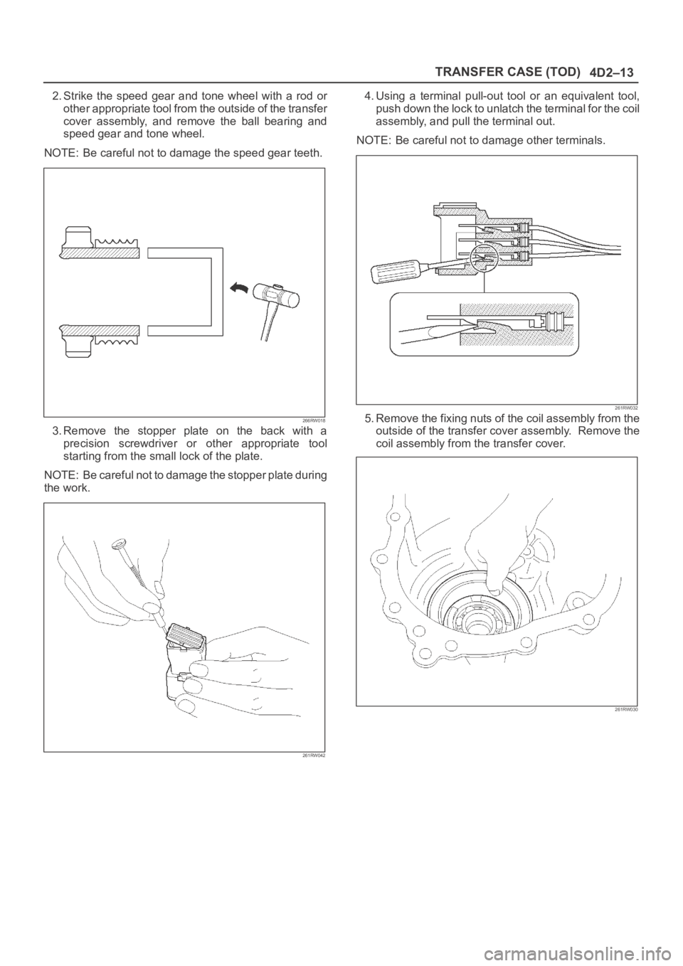
2. Strike the speed gear and tone wheel with a rod or
other appropriate tool from the outside of the transfer
cover assembly, and remove the ball bearing and
speed gear and tone wheel.
NOTE: Be careful not to damage the speed gear teeth.
266RW018
3. Remove the stopper plate on the back with a
precision screwdriver or other appropriate tool
starting from the small lock of the plate.
NOTE: Be careful not to damage the stopper plate during
the work.
261RW042
4. Using a terminal pull-out tool or an equivalent tool,
push down the lock to unlatch the terminal for the coil
assembly, and pull the terminal out.
NOTE: Be careful not to damage other terminals.
261RW032
5. Remove the fixing nuts of the coil assembly from the
outside of the transfer cover assembly. Remove the
coil assembly from the transfer cover.
261RW030
Page 4355 of 6000
5A–5 BRAKE CONTROL SYSTEM
FR
Front Right
GEN
Generator
MV
Millivolts
RL
Rear Left
RR
Rear RightRPS
Revolution per Second
VDC
Vo l t s D C
VA C
Vo l t s A C
W/L
Warning Light
WSS
Wheel Speed Sensor
General Diagnosis
General Information
ABS malfunction can be classified into two types, those
which can be detected by the ABS warning light and those
which can be detected as a vehicle abnormality by the
driver.
In either case, locate the fault in accordance with the
“BASIC DIAGNOSTIC FLOWCHART” and repair.
Please refer to Section 5C for the diagnosis of
mechanical troubles such as brake noise, brake judder
(brake pedal or vehicle vibration felt when braking),
uneven braking, and parking brake trouble.
ABS Service Precautions
Required Tools and Items:
Box Wrench
Brake Fluid
Special Tool
Some diagnosis procedures in this section require the
installation of a special tool.
J-39200 High Impedance Multimeter
When circuit measurements are requested, use a circuit
tester with high impedance.
Computer System Service Precautions
The Anti-lock Brake System interfaces directly with the
Electronic Hydraulic Control Unit (EHCU) which is a
control computer that is similar in some regards to the
Powertrain Control Module. These modules are designed
to withstand normal current draws associated with
vehicle operation. However, care must be taken to avoid
overloading any of the EHCU circuits. In testing for opens
or shorts, do not ground or apply voltage to any of the
circuits unless instructed to do so by the appropriate
diagnostic procedure. These circuits should only be
tested with a high impedance multimeter (J-39200) or
special tools as described in this section. Power should
never be removed or applied to any control module with
the ignition in the “ON” position.
Before removing or connecting battery cables, fuses or
connectors, always turn the ignition switch to the “OFF”
position.
General Service Precautions
The following are general precautions which should be
observed when servicing and diagnosing the Anti-lock
Brake System and/or other vehicle systems. Failure toobserve these precautions may result in Anti-lock Brake
System damage.
If welding work is to be performed on the vehicle using
an electric arc welder, the EHCU and valve block
connectors should be disconnected before the
welding operation begins.
The EHCU and valve block connectors should never
be connected or disconnected with the ignition “ON” .
EHCU of the Anti-lock Brake System are not
separately serviceable and must be replaced as
assemblies. Do not disassemble any component
which is designated as non-serviceable in this
Section.
If only rear wheels are rotated using jacks or drum
tester, the system will diagnose a speed sensor
malfunction and the “ABS” warning light will
illuminate. But actually no trouble exists. After
inspection stop the engine once and re-start it, then
make sure that the “ABS” warning light does not
illuminate.
If the battery has been discharged
The engine may stall if the battery has been completely
discharged and the engine is started via jumper cables.
This is because the Anti-lock Brake System (ABS)
requires a large quantity of electricity. In this case, wait
until the battery is recharged, or set the ABS to a
non-operative state by removing the fuse for the ABS
(40A). After the battery has been recharged, stop the
engine and install the ABS fuse. Start the engine again,
and confirm that the ABS warning light does not light.
Note on Intermittents
As with virtually any electronic system, it is difficult to
identify an intermittent failure. In such a case duplicating
the system malfunction during a test drive or a good
description of vehicle behavior from the customer may be
helpful in locating a “most likely” failed component or
circuit. The symptom diagnosis chart may also be useful
in isolating the failure. Most intermittent problems are
caused by faulty electrical connections or wiring. When
an intermittent failure is encountered, check suspect
circuits for:
Suspected harness damage.
Poor mating of connector halves or terminals not fully
seated in the connector body (backed out).
Improperly formed or damaged terminals.