stop start OPEL FRONTERA 1998 Repair Manual
[x] Cancel search | Manufacturer: OPEL, Model Year: 1998, Model line: FRONTERA, Model: OPEL FRONTERA 1998Pages: 6000, PDF Size: 97 MB
Page 2993 of 6000

8D–400 WIRING SYSTEM
ITEM MALFUNCTION POSSIBLE CAUSE DETECTING METHOD REMARKS
Even when door
unlocked with
key, alarm
operates.
Alarm does not
operate even with
tailgate open.
Even when
tailgate is opened
with key, alarm
does not stop.
Even when
engine hood is
opened with
remote release,
alarm does not
operate
Even when
starter switch is
turned, alarm
does not stop
Indicator light
continues
flashingRefer to “Connector
check table” in this
system.
Refer to “Connector
check table” in this
system.
Refer to “Connector
check table” in this
system. Defective contact of detect
switch, or damaged switch wiring.
Door detect switch is assembled
to wrong door.
Defective contact of tailgate
switch, or defective wiring.
Defective contact of tailgate
detect switch, or damage wiring.
Damaged engine hood switch or
wiring.
Defective contact of starter
switch.
Damaged door switch, or a short
circuit in wiring.
Damaged tamper switch, or a
short circuit in wiring.Check the control unit connector.
When key is turned to lock
position, alarm stops.
When luggage room light switch
is turned on with tailgate open,
luggage room light does not
come on.
Check the control unit connector.
With starter switch turned to
“ACC” position, audio, cigarette
lighter and door mirrors (on
“ACC” circuit) do not operate.
After closing door, dome light and
courtesy light remain on.
Check the control unit connector. F
G
H
I
J
K
Page 2994 of 6000

WIRING SYSTEM 8D–401
STEP OPERATION ITEM TO BE CHECKEDITEM OF
REMARKS
MALFUNCTION
Be sure to lock door
with locking knob.
Activate alarm
device.
All doors are
unlocked.
With key set at unlock
position, check to see
if alarm stops.
All doors are
locked.
Activate alarm
device.
Activate alarm
device.
Only left rear door
is unlocked. Check to see if engine hood,
tailgate and doors are closed and
locked.
Check to see if indicator light
remains lit off.
Check to see if indicator light
flashes.
Check to see if dome light and
courtesy light illuminate.
Check to see if indicator light
changes from flashing to steadily
on.
Check to see if indicator light
turns off in about 10 seconds.
Check to see if alarm operates
(with headlight flashing, and horn
blaring intermittently.)
Check to see if alarm stops.
Check to see if indicator light
turns on.
Check to see if indicator light
goes off after about 10 seconds.
Check to see if alarm does not
operate.
Check to see if indicator light
turns on.
Check to see if indicator light
goes off after about 10 seconds.
Check to see if alarm starts. Turn starter key to “ON” position.
Open windows fully.
Pull out starter key after turning it
back to “OFF” position.
Unlock left front door with locking
knob.
Open left front door. (And get out
of the vehicle.)
Close left front door.
Lock left front door.
Wait about 10 seconds
Unlock left front door with locking
knob.
Insert key into key cylinder of left
front door and turn it in unlock
direction.
Lock left front door.
Wait for about 10 seconds.
Unlock left front door with key.
Lock left front door with key.
Wait for about 10 seconds.
Unlock left rear door with locking
knob.K
A
B
C
D
E
B
C
F
B
C
D 1
2
3
4
5
6
7
8
9
10
11
12
13
14
15
16
Page 2997 of 6000
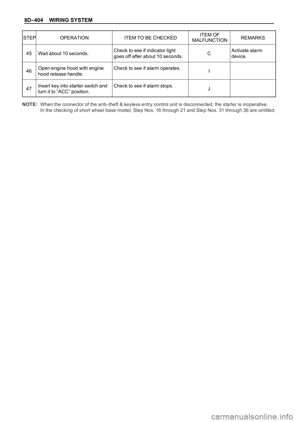
8D–404 WIRING SYSTEM
STEP OPERATION ITEM TO BE CHECKEDITEM OF
REMARKS
MALFUNCTION
Activate alarm
device. Check to see if indicator light
goes off after about 10 seconds.
Check to see if alarm operates.
Check to see if alarm stops. Wait about 10 seconds.
Open engine hood with engine
hood release handle.
Insert key into starter switch and
turn it to “ACC” position.C
I
J 45
46
47
NOTE:When the connector of the anti–theft & keyless entry control unit is disconnected, the starter is inoperative.
In the checking of short wheel base model, Step Nos. 16 through 21 and Step Nos. 31 through 36 are omitted.
Page 3078 of 6000
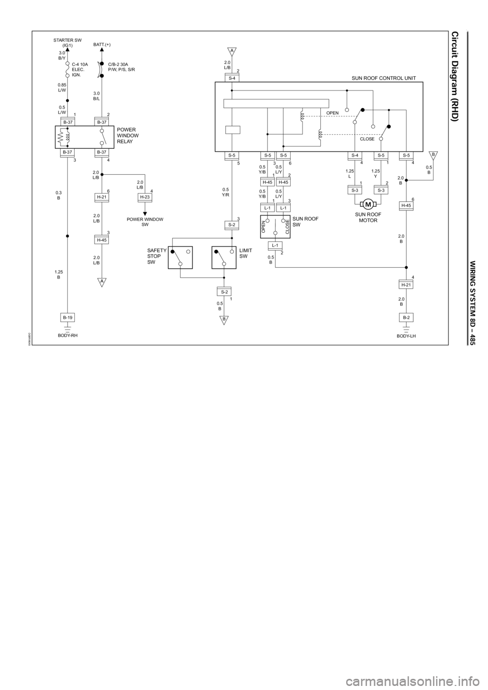
D08RW649
2
B-37
B-37
1
4 3 B-37
B-37
6
H-21
3.0
B/Y STARTER SW
(IG1)BATT.(+)
C-4 10A
ELEC.
IGN.C/B-2 30A
P/W, P/S, S/R
0.85
L/W
3.0
B/L
2.0
L/B 2.0
L/B
2.0
L/B
0.5
B0.5
Y/R0.5
Y/B
0.5
Y/B0.5
L/Y1.25
L1.25
Y
0.5
L/Y
2.0
L/B 0.5
L/W
B-19
BODY-RH 1.25
B 0.3
B
POWER
WINDOW
RELAY
SAFETY
STOP
SWLIMIT
SWSUN ROOF
SWSUN ROOF
MOTOR
3
H-45
4
H-21
2.0
B
BODY-LH 4
H-23
POWER WINDOW
SW6
H-454
S-5
0.5
B
2.0
B
2.0
B
1 S-2
3S-2
2 1 5
S-5 2.0
L/B
B-2
L-1
OPEN
CLOSE
0.5
B L-13
L-1 1
H-452H-45 2
S-4
3
S-5
6S-5OPEN
SUN ROOF CONTROL UNIT
CLOSE
1S-5
4S-4
1
S-32S-3
Page 3080 of 6000
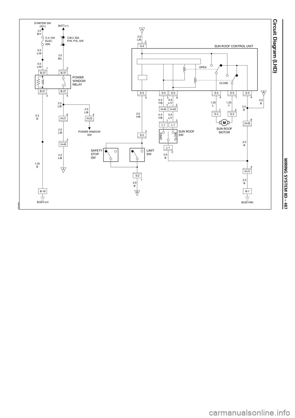
D08RW947
2
B-37
B-37
1
4 3 B-37
B-37
6
H-21
3.0
B/Y STARTER SW
(IG1)BATT.(+)
C-4 10A
ELEC.
IGN.C/B-2 30A
P/W, P/S, S/R
0.5
L/W
3.0
B/L
2.0
L/B 2.0
L/B
2.0
L/B
0.5
B0.5
Y/R0.5
Y/B
0.5
Y/B0.5
L/Y1.25
L1.25
Y
0.5
L/Y
2.0
L/B 0.5
L/W
B-18
BODY-LH 1.25
B 0.3
B
POWER
WINDOW
RELAY
SAFETY
STOP
SWLIMIT
SWSUN ROOF
SWSUN ROOF
MOTOR
A
3
H-45
4
H-21
2.0
B
BODY-RH 4
H-23
POWER WINDOW
SW6
H-454
S-5
0.5
B
2.0
B
2.0
B
B
A
B
1 S-2
3S-2
2 1 5
S-5 2.0
L/B
B-1
L-1
OPEN
CLOSE
0.5
B L-13
L-1 1
H-452H-45 2
S-4
3
S-5
6S-5OPEN
SUN ROOF CONTROL UNIT
CLOSE
1S-5
4S-4
1
S-32S-3
M
Page 3132 of 6000
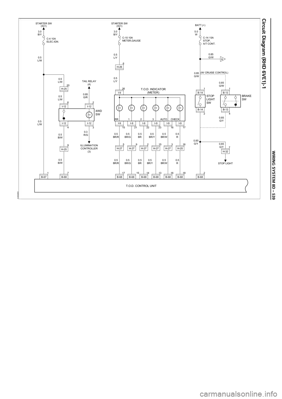
D08RW610
3.0
B/Y
0.5
L/W
0.5
L/W
0.5
L/W 0.85
G/R
0.5
B/W 0.3
R/G 0.5
BR/R 0.5
BR/G 0.5
BR 0.5
BR/Y 0.5
BR/W 0.5
R
0.5
BR/R 0.5
BR/G 0.5
BR 0.5
BR/Y 0.5
BR/W 0.5
R
0.5
B/W
0.5
L/W C-4 10A
ELEC.IGN.
4WD
SW BRAKE
SW
STOP
LIGHT
SW
T.O.D. INDICATOR
(METER)
T.O.D. CONTROL UNIT
TAIL RELAY (4)
ILLUMINATION CONTROLLER (3)
1B-67 7B-68 9
H-25
3.0
B/Y
0.5
L/Y
0.5
L/Y C-10 10A
METER,GAUGE
STARTER SW (IG1)
STARTER SW
(IG1)
6
I-12 4
I-12 2
I-12
3
I-12 20
H-25
17B-68
5.0
W
0.85
G/W
C-14 15A
STOP,
A/T CONT.
BATT.(+)
STOP LIGHT
2B-68
5
H-27 26
I-9
15
I-9
15B-68 9
H-27
21
I-9
14B-68 2
H-27
22
I-9
13B-68 15
H-27
23
I-9
16B-68 3
H-27
16
I-9
18B-68 16
H-25
7H-32
17
I-9
6
H-26
0.85
G/W
0.85
G/W (W/ CRUISE CONTROL)
0.85 G/Y
0.85 G/Y
0.85
G/Y
B-13 1
B-13
4
B-14 1
B-14
2
RR 1 2 3 AUTO CHECK
A
Page 3417 of 6000
8J–38EXTERIOR/INTERIOR TRIM
Power Door Mirror System
General Description
The circuit consists of the starter switch, door mirror
control switch, folding switch, defogger switch and door
mirrors on both sides.
The door mirror switch consists of the control switch,
folding switch and defogger switch.
When the control switch is operated with the starter
switch at either “ACC” or “ON” position, the motors
incorporated in the door mirrors on both sides rotates to
allow the horizontal and vertical adjustment of mirror
angles.
The folding switch can be used to fold the mirror and
return it to its original position.
When turning on the door mirror defogger switch with the
starter switch at “ON” position, built-in heater in the mirror
is activated to perform the defogger function.
Door Mirror Switch Assembly (Con-
trol Switch, Folding Switch and De-
fogger Switch) Removal
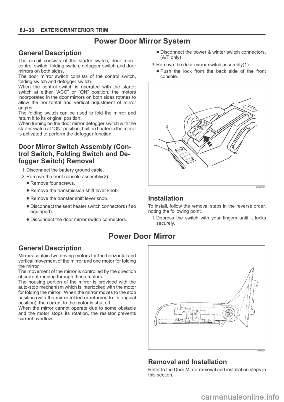
1. Disconnect the battery ground cable.
2. Remove the front console assembly(2).
Remove four screws.
Remove the transmission shift lever knob.
Remove the transfer shift lever knob.
Disconnect the seat heater switch connectors (if so
equipped).
Disconnect the door mirror switch connectors.
Disconnect the power & winter switch connectors.
(A/T only)
3. Remove the door mirror switch assembly(1).
Push the lock from the back side of the front
console.
825RS005
Installation
To install, follow the removal steps in the reverse order,
noting the following point.
1. Depress the switch with your fingers until it locks
securely.
Power Door Mirror
General Description
Mirrors contain two driving motors for the horizontal and
vertical movement of the mirror and one motor for folding
the mirror.
The movement of the mirror is controlled by the direction
of current running through these motors.
The housing portion of the mirror is provided with the
auto-stop mechanism which is interlocked with the motor
for folding the mirror. When the mirror moves to the stop
position (with the mirror folded or returned to its original
position), the current to the motor is shut off.
When the mirror cannot operate due to some obstacle
and the motor stops its rotation, the resistor prevents
current overflow.
720RS004
Removal and Installation
Refer to the Door Mirror removal and installation steps in
this section.
Page 3478 of 6000
SUPPLEMENTAL RESTRAINT SYSTEM9J–41
Installation
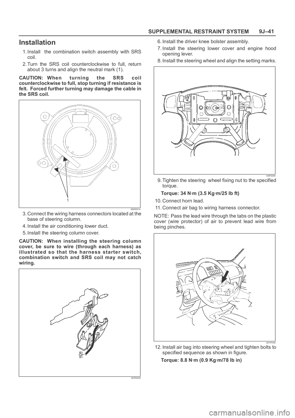
1. Install the combination switch assembly with SRS
coil.
2. Turn the SRS coil counterclockwise to full, return
about 3 turns and align the neutral mark (1).
CAUTION: W h e n t u r n i n g t h e S R S c o i l
counterclockwise to full, stop turning if resistance is
felt. Forced further turning may damage the cable in
the SRS coil.
826RW014
3. Connect the wiring harness connectors located at the
base of steering column.
4. Install the air conditioning lower duct.
5. Install the steering column cover.
CAUTION: When installing the steering column
cover, be sure to wire (through each harness) as
illustrated so that the harness starter switch,
combination switch and SRS coil may not catch
wiring.
825RS048
6. Install the driver knee bolster assembly.
7. Install the steering lower cover and engine hood
opening lever.
8. Install the steering wheel and align the setting marks.
430RS004
9. Tighten the steering wheel fixing nut to the specified
torque.
Torque: 34 Nꞏm (3.5 Kgꞏm/25 Ib ft)
10. Connect horn lead.
11. Connect air bag to wiring harness connector.
NOTE: Pass the lead wire through the tabs on the plastic
cover (wire protector) of air to prevent lead wire from
being pinches.
827RT009
12. Install air bag into steering wheel and tighten bolts to
specified sequence as shown in figure.
Torque: 8.8 Nꞏm (0.9 Kgꞏm/78 Ib in)
Page 3483 of 6000
SUPPLEMENTAL RESTRAINT SYSTEM 9J–46
NOTE: SRS coil is a part of combination switch
assembly, which cannot be replaced separately.
Therefore, be sure not to remove the SRS coil from the
combination switch assembly.
15. Remove the snap ring.
16. Remove the cushion rubber.
17. Disconnect shift lock cable (A/T only).
18. Disconnect the starter switch harness connector
located base of steering column.
19. Remove steering lock cylinder assembly.
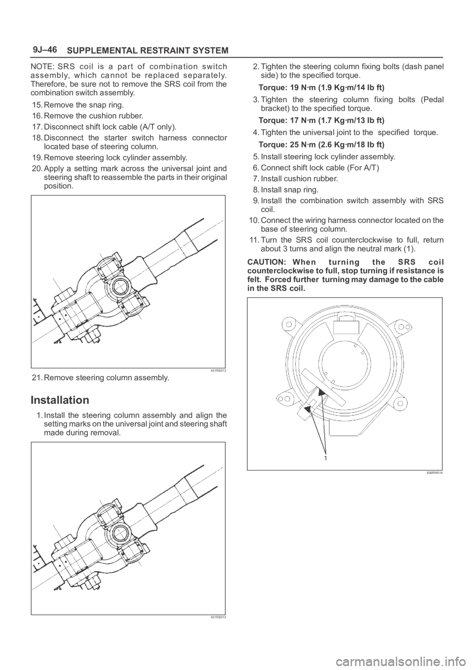
20. Apply a setting mark across the universal joint and
steering shaft to reassemble the parts in their original
position.
431RS013
21. Remove steering column assembly.
Installation
1. Install the steering column assembly and align the
setting marks on the universal joint and steering shaft
made during removal.
431RS013
2. Tighten the steering column fixing bolts (dash panel
side) to the specified torque.
Torque: 19 Nꞏm (1.9 Kgꞏm/14 Ib ft)
3. Tighten the steering column fixing bolts (Pedal
bracket) to the specified torque.
Torque: 17 Nꞏm (1.7 Kgꞏm/13 Ib ft)
4. Tighten the universal joint to the specified torque.
Torque: 25 Nꞏm (2.6 Kgꞏm/18 Ib ft)
5. Install steering lock cylinder assembly.
6. Connect shift lock cable (For A/T)
7. Install cushion rubber.
8. Install snap ring.
9. Install the combination switch assembly with SRS
coil.
10. Connect the wiring harness connector located on the
base of steering column.
11. Turn the SRS coil counterclockwise to full, return
about 3 turns and align the neutral mark (1).
CAUTION: W h e n t u r n i n g t h e S R S c o i l
counterclockwise to full, stop turning if resistance is
felt. Forced further turning may damage to the cable
in the SRS coil.
826RW014
Page 3784 of 6000

1. Perform oil return operation.
2. Discharge and recover the refrigerant and remove
the compressor.
3. Drain the compressor oil and measure the extracted
oil.
4. Check the compressor oil for contamination.
5. Adjust the oil level as required.
6. Evacuate, charge and perform the oil return
operation.
7. Check the system operation.
Contamination of Compressor Oil
Unlike engine oil, no cleaning agent is added to the
compressor oil. Even if the compressor runs for a long
period of time (approximately one season), the oil never
becomes contaminated as long as there is nothing
wrong with the compressor or its method of use.
Inspect the extracted oil for any of the following
conditions:
The capacity of the oil has increased.
The oil has changed to red.
Foreign substances, metal powder, etc., are present
in the oil.
If any of these conditions exists, the compressor
oil is contaminated. Whenever contaminated
compressor oil is discovered, the receiver/drier
must be replaced.
Oil Return Operation
There is close affinity between the oil and the
refrigerant. During normal operation, part of the oil
recirculates with the refrigerant in the system. When
checking the amount of oil in the system, or replacing
any component of the system, the compressor must be
run in advance for oil return operation. The procedure
is as follows:
1. Open all the doors and the engine hood.
2. Start the engine and air conditioning switch to "ON"
and set the fan control knob at its highest position.
3. Run the compressor for more than 20 minutes
between 800 and 1,000 rpm in order to operate the
system.
4. Stop the engine.
Replacement of Component Parts
When replacing the system component parts, supply
the following amount of oil to the component parts to be
installed.
Compressor Leak Testing (External and
Internal)
Bench-Check Procedure
1. Install test plate J-39893 on rear head of compressor.
2. Using Refrigerant Recovery System, attach center
hose of manifold gage set on charging station to a
refrigerant drum standing in an upright drum.
3. Connect charging station high and low pressure
lines to corresponding fittings on test plate J-39893.
Suction port (low-side) of compressor has large
internal opening. Discharge port (high-side) has
smaller internal opening into compressor and
deeper recess.
4. Open low pressure control, high pressure control
and refrigerant control on charging station to allow
refrigerant vapor to flow into compressor.
5. Using a leak detector, check for leaks at pressure
relief valve, rear head switch location, compressor
front and rear head seals, center cylinder seal,
through bolt head gaskets and compressor shaft
seal. After checking, shut off low pressure control
and high-pressure control on charging station.
6. If an external leak is present, perform the necessary
corrective measures and recheck for leaks to make
certain the leak has been connected.
7. Recover the refrigerant.
8. Disconnect both hoses from the test plate J-39893.
9. Add 90 ml (3 oz.) new PAG lubricant to the
compressor assembly. Rotate the complete
compressor assembly (not the crankshaft or drive
plate hub) slowly several turns to distribute oil to all
cylinder and piston areas.
10. Install a M9
1.25 threaded nut on the compressor
crankshaft if the drive plate and clutch assembly are
not installed.
11. Using a box-end wrench or socket and handle,
rotate the compressor crankshaft or clutch drive
plate on the crankshaft several turns to insure
piston assembly to cylinder wall lubrication.
12. Using Refrigerant Recovery System, connect the
charging station high-pressure line to the test plate
J-39893 high-side connector.
13. Using Refrigerant Recovery System, connect the
charging station low-pressure line to the low
pressure port of the test plate J-39893. Oil will drain
out of the compressor suction port if the compressor
is positioned with the suction port downward. (Component parts to be (Amount of Oil)
installed)
Evaporator 50 cc (1.7 fl. oz.)
Condenser 30 cc (1.0 fl. oz.)
Receiver/dryer 30 cc (1.0 fl. oz.)
Refrigerant line (one 10 cc (0.3 fl. oz.)
piece)
(Amount of oil drained (Charging amount of oil
from used compressor) to new compressor)
more than 90 cc same as drained amount
(3.0 fl.oz)
less than 90 cc (3.0 fl.oz) 90 cc (3.0 fl.oz)