stop start OPEL FRONTERA 1998 Manual PDF
[x] Cancel search | Manufacturer: OPEL, Model Year: 1998, Model line: FRONTERA, Model: OPEL FRONTERA 1998Pages: 6000, PDF Size: 97 MB
Page 4356 of 6000
5A–6
BRAKE CONTROL SYSTEM
Test Driving ABS Complaint Vehicles
In case that there has been an malfunction in the lighting
pattern of “ABS” warning light, the fault can be located in
accordance with the “DIAGNOSIS BY “ABS” WARNING
LIGHT ILLUMINATION PATTERN” . In case of such
trouble as can be detected by the driver as a vehicle
symptom, however, it is necessary to give a test drive
following the test procedure mentioned below, thereby
reproducing the symptom for trouble diagnosis on a
symptom basis:
1. Start the engine and make sure that the “ABS” W/L
goes OFF. If the W/L remains ON, it means that the
Diagnostic Trouble Code (DTC) is stored. Therefore,
read the code and locate the fault.
2. Start the vehicle and accelerate to about 30 km/h (19
mph) or more.
3. Slowly brake and stop the vehicle completely.
4. Then restart the vehicle and accelerate to about 40
km/h (25 mph) or more.
5. Brake at a time so as to actuate the ABS and stop the
vehicle.
6. Be cautious of abnormality during the test. If the W/L
is actuated while driving, read the DTC and locate the
fault.
7. If the abnormality is not reproduced by the test, make
best efforts to reproduce the situation reported by the
customer.
8. If the abnormality has been detected, repair in
accordance with the “SYMPTOM DIAGNOSIS” .NOTE:Be sure to give a test drive on a wide, even road with
little traffic.
If an abnormality is detected, be sure to suspend the
test and start trouble diagnosis at once.
“ABS” Warning Light
When ABS trouble occurs and actuates when possible
the “ABS” warning light, the trouble code corresponding
to the trouble is stored in the EHCU. Only the ordinary
brake system is available when the ABS is turned off.
When the “ABS” warning light is actuated, if the starter
switch is set ON after setting it OFF once, the EHCU
checks up on the entire system and, if there is no
abnormality, judges ABS to work currently and the
warning light works normally even though the trouble
code is stored.
NOTE: Illumination of the “ABS” warning light indicates
that anti-lock braking is no longer available. Power
assisted braking without anti-lock control is still available.
Normal Operation
“ABS” Warning Light
W h e n t h e i g n i t i o n i s f i r s t m o v e d f r o m “ O F F ” t o “ R U N ” , t h e
amber “ABS” warning light will turn “ON” . The “ABS”
warning light will turn “ON” during engine starting and will
usually stay “ON” for approximately three seconds after
the ignition switch is returned to the “ON” position. The
warning light should remain “OFF” at all other times.
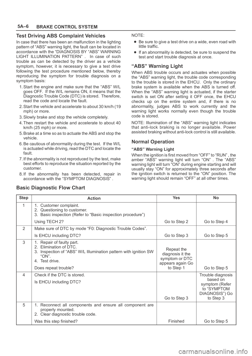
Basic Diagnostic Flow Chart
StepActionYe sNo
11. Customer complaint.
2. Questioning to customer.
3. Basic inspection (Refer to “Basic inspection procedure”)
Using TECH 2?
Go to Step 2Go to Step 4
2Make sure of DTC by mode “F0: Diagnostic Trouble Codes”.
Is EHCU including DTC?
Go to Step 3Go to Step 5
31. Repair of faulty part.
2. Elimination of DTC.
3. Inspection of “ABS” W/L Illumination pattern with ignition SW
“ON”.
4. Test drive.
Does repeat trouble?
Repeat the
diagnosis it the
symptom or DTC
appears again Go
to Step 1
Go to Step 5
4Check if the DTC is stored.
Is EHCU including DTC?
Go to Step 3
Trouble diagnosis
based on
symptom (Refer
to “SYMPTOM
DIAGNOSIS”) Go
to Step 3
51. Reconnect all components and ensure all component are
properly mounted.
2. Clear diagnostic trouble code.
Was this step finished?
FinishedGo to Step 5
Page 4361 of 6000
5A–11 BRAKE CONTROL SYSTEM
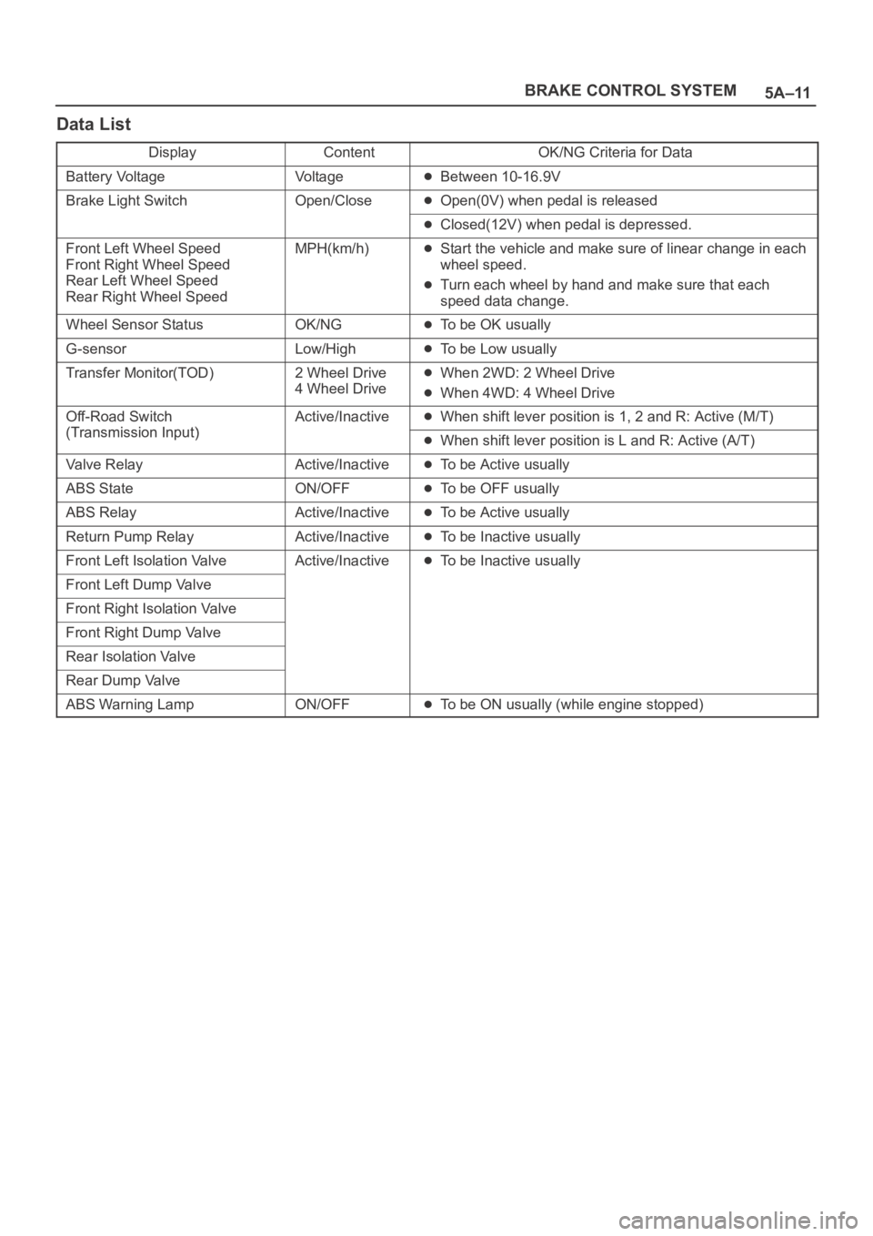
Data List
DisplayContentOK/NG Criteria for Data
Battery VoltageVo l t a g eBetween 10-16.9V
Brake Light SwitchOpen/CloseOpen(0V) when pedal is released
Closed(12V) when pedal is depressed.
Front Left Wheel Speed
Front Right Wheel Speed
Rear Left Wheel Speed
Rear Right Wheel SpeedMPH(km/h)Start the vehicle and make sure of linear change in each
wheel speed.
Turn each wheel by hand and make sure that each
speed data change.
Wheel Sensor StatusOK/NGTo be OK usually
G-sensorLow/HighTo be Low usually
Transfer Monitor(TOD)2 Wheel Drive
4 Wheel DriveWhen 2WD: 2 Wheel Drive
When 4WD: 4 Wheel Drive
Off-Road Switch
(Transmission Input)
Active/InactiveWhen shift lever position is 1, 2 and R: Active (M/T)
(Transmission Input)When shift lever position is L and R: Active (A/T)
Valve RelayActive/InactiveTo be Active usually
ABS StateON/OFFTo be OFF usually
ABS RelayActive/InactiveTo be Active usually
Return Pump RelayActive/InactiveTo be Inactive usually
Front Left Isolation ValveActive/InactiveTo be Inactive usually
Front Left Dump Valve
Front Right Isolation Valve
Front Right Dump Valve
Rear Isolation Valve
Rear Dump Valve
ABS Warning LampON/OFFTo be ON usually (while engine stopped)
Page 4390 of 6000
5A–40
BRAKE CONTROL SYSTEM
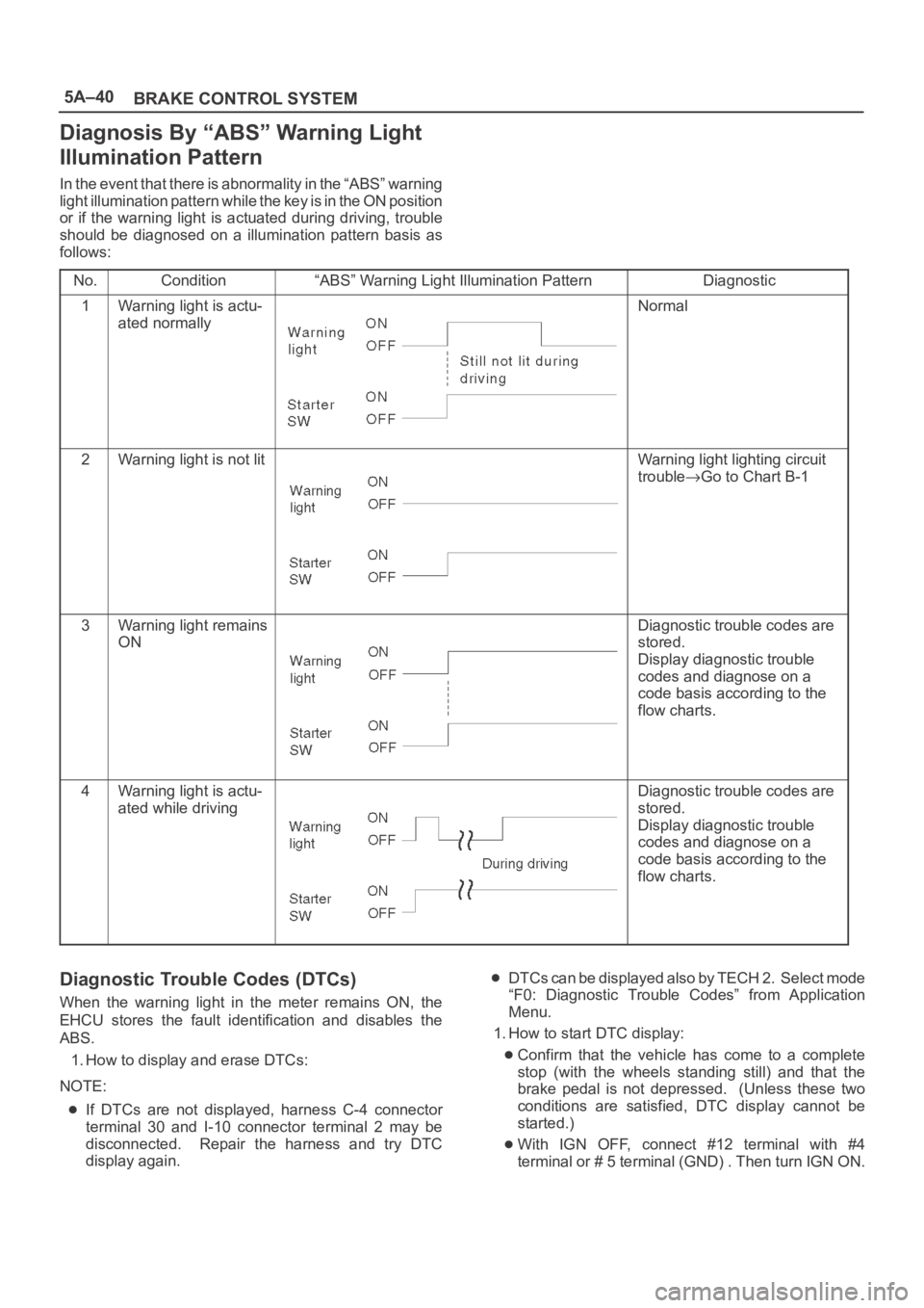
Diagnosis By “ABS” Warning Light
Illumination Pattern
In the event that there is abnormality in the “ABS” warning
light illumination pattern while the key is in the ON position
or if the warning light is actuated during driving, trouble
should be diagnosed on a illumination pattern basis as
follows:
No.
Condition“ABS” Warning Light Illumination PatternDiagnostic
1Warning light is actu-
ated normallyNormal
2Warning light is not litWarning light lighting circuit
trouble
Go to Chart B-1
3Warning light remains
ONDiagnostic trouble codes are
stored.
Display diagnostic trouble
codes and diagnose on a
code basis according to the
flow charts.
4Warning light is actu-
ated while drivingDiagnostic trouble codes are
stored.
Display diagnostic trouble
codes and diagnose on a
code basis according to the
flow charts.
Diagnostic Trouble Codes (DTCs)
When the warning light in the meter remains ON, the
EHCU stores the fault identification and disables the
ABS.
1. How to display and erase DTCs:
NOTE:
If DTCs are not displayed, harness C-4 connector
terminal 30 and I-10 connector terminal 2 may be
disconnected. Repair the harness and try DTC
display again.
DTCs can be displayed also by TECH 2. Select mode
“F0: Diagnostic Trouble Codes” from Application
Menu.
1. How to start DTC display:
Confirm that the vehicle has come to a complete
stop (with the wheels standing still) and that the
brake pedal is not depressed. (Unless these two
conditions are satisfied, DTC display cannot be
started.)
With IGN OFF, connect #12 terminal with #4
terminal or # 5 terminal (GND) . Then turn IGN ON.
Page 4391 of 6000
5A–41 BRAKE CONTROL SYSTEM
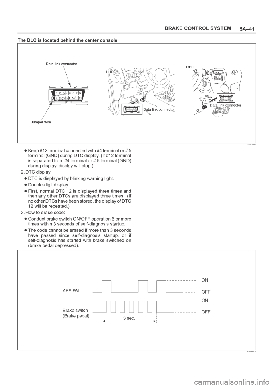
The DLC is located behind the center console
350RV010
Keep #12 terminal connected with #4 terminal or # 5
terminal (GND) during DTC display. (If #12 terminal
is separated from #4 terminal or # 5 terminal (GND)
during display, display will stop.)
2. DTC display:
DTC is displayed by blinking warning light.
Double-digit display.
First, normal DTC 12 is displayed three times and
then any other DTCs are displayed three times. (If
no other DTCs have been stored, the display of DTC
12 will be repeated.)
3. How to erase code:
Conduct brake switch ON/OFF operation 6 or more
times within 3 seconds of self-diagnosis startup.
The code cannot be erased if more than 3 seconds
have passed since self-diagnosis startup, or if
self-diagnosis has started with brake switched on
(brake pedal depressed).
B05RW005
Page 4507 of 6000
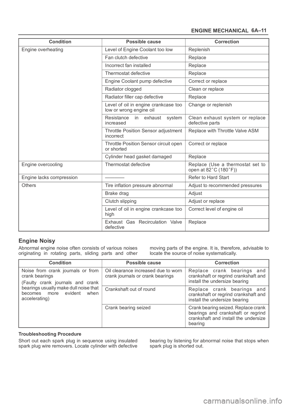
6A–11
ENGINE MECHANICAL
Condition CorrectionPossible cause
Engine overheatingLevel of Engine Coolant too lowReplenish
Fan clutch defectiveReplace
Incorrect fan installedReplace
Thermostat defectiveReplace
Engine Coolant pump defectiveCorrect or replace
Radiator cloggedClean or replace
Radiator filler cap defectiveReplace
Level of oil in engine crankcase too
low or wrong engine oilChange or replenish
Resistance in exhaust system
increasedClean exhaust system or replace
defective parts
Throttle Position Sensor adjustment
incorrectReplace with Throttle Valve ASM
Throttle Position Sensor circuit open
or shortedCorrect or replace
Cylinder head gasket damagedReplace
Engine overcoolingThermostat defectiveReplace (Use a thermostat set to
open at 82
C (180F))
Engine lacks compression————Refer to Hard Start
OthersTire inflation pressure abnormalAdjust to recommended pressures
Brake dragAdjust
Clutch slippingAdjust or replace
Level of oil in engine crankcase too
highCorrect level of engine oil
Exhaust Gas Recirculation Valve
defectiveReplace
Engine Noisy
Abnormal engine noise often consists of various noises
originating in rotating parts, sliding parts and othermoving parts of the engine. It is, therefore, advisable to
locate the source of noise systematically.
Condition
Possible causeCorrection
Noise from crank journals or from
crank bearings
(Faulty crank journals and crankOil clearance increased due to worn
crank journals or crank bearingsReplace crank bearings and
crankshaft or regrind crankshaft and
install the undersize bearing
yj
bearings usually make dull noise that
becomes more evident when
accelerating)Crankshaft out of roundReplace crank bearings and
crankshaft or regrind crankshaft and
install the undersize bearing
Crank bearing seizedCrank bearing seized. Replace crank
bearings and crankshaft or regrind
crankshaft and install the undersize
bearing
Troubleshooting Procedure
Short out each spark plug in sequence using insulated
spark plug wire removers. Locate cylinder with defectivebearing by listening for abnormal noise that stops when
spark plug is shorted out.
Page 4512 of 6000
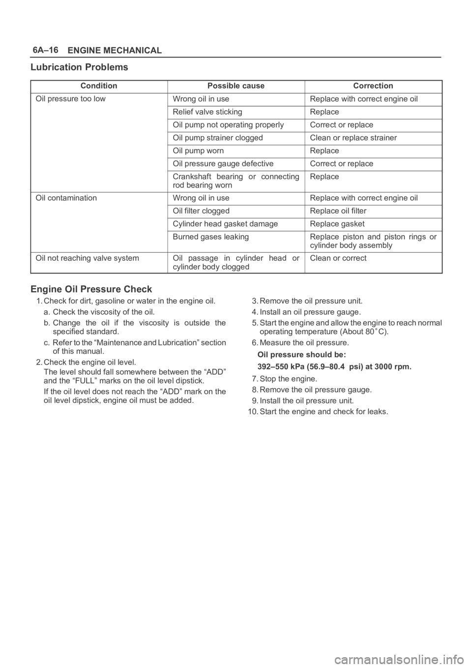
6A–16
ENGINE MECHANICAL
Lubrication Problems
ConditionPossible causeCorrection
Oil pressure too lowWrong oil in useReplace with correct engine oil
Relief valve stickingReplace
Oil pump not operating properlyCorrect or replace
Oil pump strainer cloggedClean or replace strainer
Oil pump wornReplace
Oil pressure gauge defectiveCorrect or replace
Crankshaft bearing or connecting
rod bearing wornReplace
Oil contaminationWrong oil in useReplace with correct engine oil
Oil filter cloggedReplace oil filter
Cylinder head gasket damageReplace gasket
Burned gases leakingReplace piston and piston rings or
cylinder body assembly
Oil not reaching valve systemOil passage in cylinder head or
cylinder body cloggedClean or correct
Engine Oil Pressure Check
1. Check for dirt, gasoline or water in the engine oil.
a. Check the viscosity of the oil.
b. Change the oil if the viscosity is outside the
specified standard.
c. Refer to the “Maintenance and Lubrication” section
of this manual.
2. Check the engine oil level.
The level should fall somewhere between the “ADD”
and the “FULL” marks on the oil level dipstick.
If the oil level does not reach the “ADD” mark on the
oil level dipstick, engine oil must be added.3. Remove the oil pressure unit.
4. Install an oil pressure gauge.
5. Start the engine and allow the engine to reach normal
operating temperature (About 80
C).
6. Measure the oil pressure.
Oil pressure should be:
392–550 kPa (56.9–80.4 psi) at 3000 rpm.
7. Stop the engine.
8. Remove the oil pressure gauge.
9. Install the oil pressure unit.
10. Start the engine and check for leaks.
Page 4599 of 6000
6B–6
ENGINE COOLING
Draining and Refilling Cooling
System
Before draining the cooling system, inspect the system
and perform any necessary service to ensure that it is
clean, does not leak and is in proper working order. The
engine coolant (EC) level should be between the “MIN”
and “MAX” lines of reserve tank when the engine is cold.
If low, check for leakage and add EC up to the “MAX” line.
There should not be any excessive deposit of rust or
scales around the radiator cap or radiator filler hole, and
the EC should also be free from oil.
Replace the EC if excessively dirty.
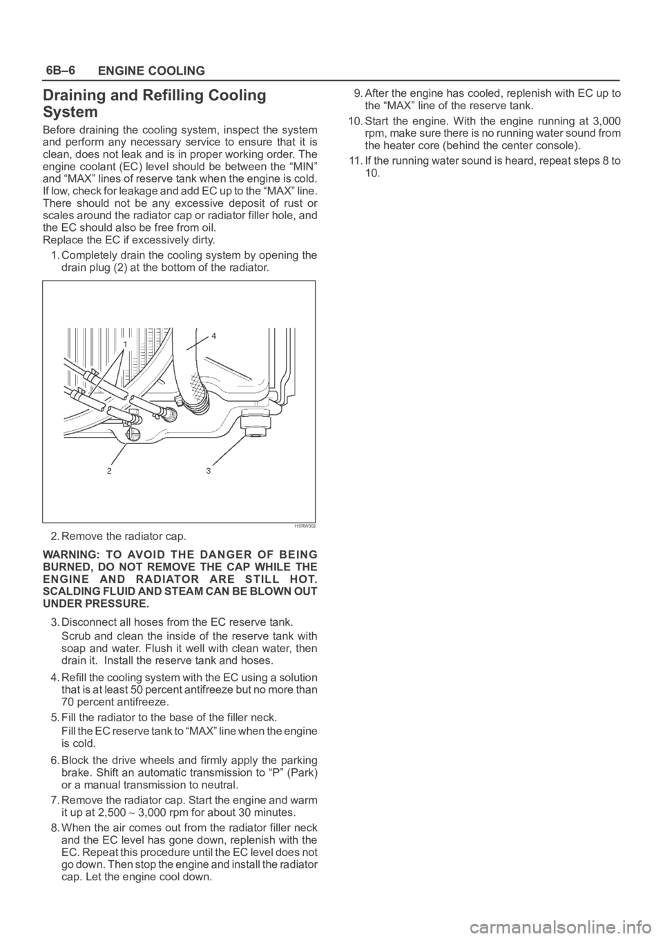
1. Completely drain the cooling system by opening the
drain plug (2) at the bottom of the radiator.
110RW002
2. Remove the radiator cap.
WARNING: TO AVOID THE DANGER OF BEING
BURNED, DO NOT REMOVE THE CAP WHILE THE
ENGINE AND RADIATOR ARE STILL HOT.
SCALDING FLUID AND STEAM CAN BE BLOWN OUT
UNDER PRESSURE.
3. Disconnect all hoses from the EC reserve tank.
Scrub and clean the inside of the reserve tank with
soap and water. Flush it well with clean water, then
drain it. Install the reserve tank and hoses.
4. Refill the cooling system with the EC using a solution
that is at least 50 percent antifreeze but no more than
70 percent antifreeze.
5. Fill the radiator to the base of the filler neck.
Fill the EC reserve tank to “MAX” line when the engine
is cold.
6. Block the drive wheels and firmly apply the parking
brake. Shift an automatic transmission to “P” (Park)
or a manual transmission to neutral.
7. Remove the radiator cap. Start the engine and warm
it up at 2,500
3,000 rpm for about 30 minutes.
8. When the air comes out from the radiator filler neck
and the EC level has gone down, replenish with the
EC. Repeat this procedure until the EC level does not
go down. Then stop the engine and install the radiator
cap. Let the engine cool down.9. After the engine has cooled, replenish with EC up to
the “MAX” line of the reserve tank.
10. Start the engine. With the engine running at 3,000
rpm, make sure there is no running water sound from
the heater core (behind the center console).
11. If the running water sound is heard, repeat steps 8 to
10.
Page 4604 of 6000
ENGINE COOLING6B–11
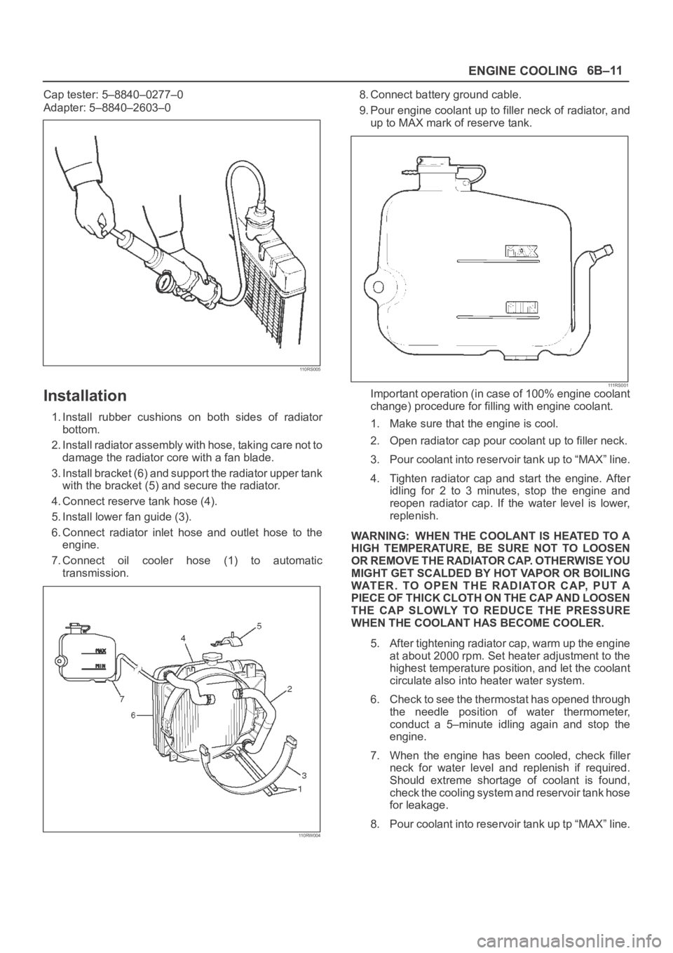
Cap tester: 5–8840–0277–0
Adapter: 5–8840–2603–0
110RS005
Installation
1. Install rubber cushions on both sides of radiator
bottom.
2. Install radiator assembly with hose, taking care not to
damage the radiator core with a fan blade.
3. Install bracket (6) and support the radiator upper tank
with the bracket (5) and secure the radiator.
4. Connect reserve tank hose (4).
5. Install lower fan guide (3).
6. Connect radiator inlet hose and outlet hose to the
engine.
7. Connect oil cooler hose (1) to automatic
transmission.
110RW004
8. Connect battery ground cable.
9. Pour engine coolant up to filler neck of radiator, and
up to MAX mark of reserve tank.
111 R S 0 0 1Important operation (in case of 100% engine coolant
change) procedure for filling with engine coolant.
1. Make sure that the engine is cool.
2. Open radiator cap pour coolant up to filler neck.
3. Pour coolant into reservoir tank up to “MAX” line.
4. Tighten radiator cap and start the engine. After
idling for 2 to 3 minutes, stop the engine and
reopen radiator cap. If the water level is lower,
replenish.
WARNING: WHEN THE COOLANT IS HEATED TO A
HIGH TEMPERATURE, BE SURE NOT TO LOOSEN
OR REMOVE THE RADIATOR CAP. OTHERWISE YOU
MIGHT GET SCALDED BY HOT VAPOR OR BOILING
WATER. TO OPEN THE RADIATOR CAP, PUT A
PIECE OF THICK CLOTH ON THE CAP AND LOOSEN
THE CAP SLOWLY TO REDUCE THE PRESSURE
WHEN THE COOLANT HAS BECOME COOLER.
5. After tightening radiator cap, warm up the engine
at about 2000 rpm. Set heater adjustment to the
highest temperature position, and let the coolant
circulate also into heater water system.
6. Check to see the thermostat has opened through
the needle position of water thermometer,
conduct a 5–minute idling again and stop the
engine.
7. When the engine has been cooled, check filler
neck for water level and replenish if required.
Should extreme shortage of coolant is found,
check the cooling system and reservoir tank hose
for leakage.
8. Pour coolant into reservoir tank up tp “MAX” line.
Page 4612 of 6000
6C–5
ENGINE FUEL
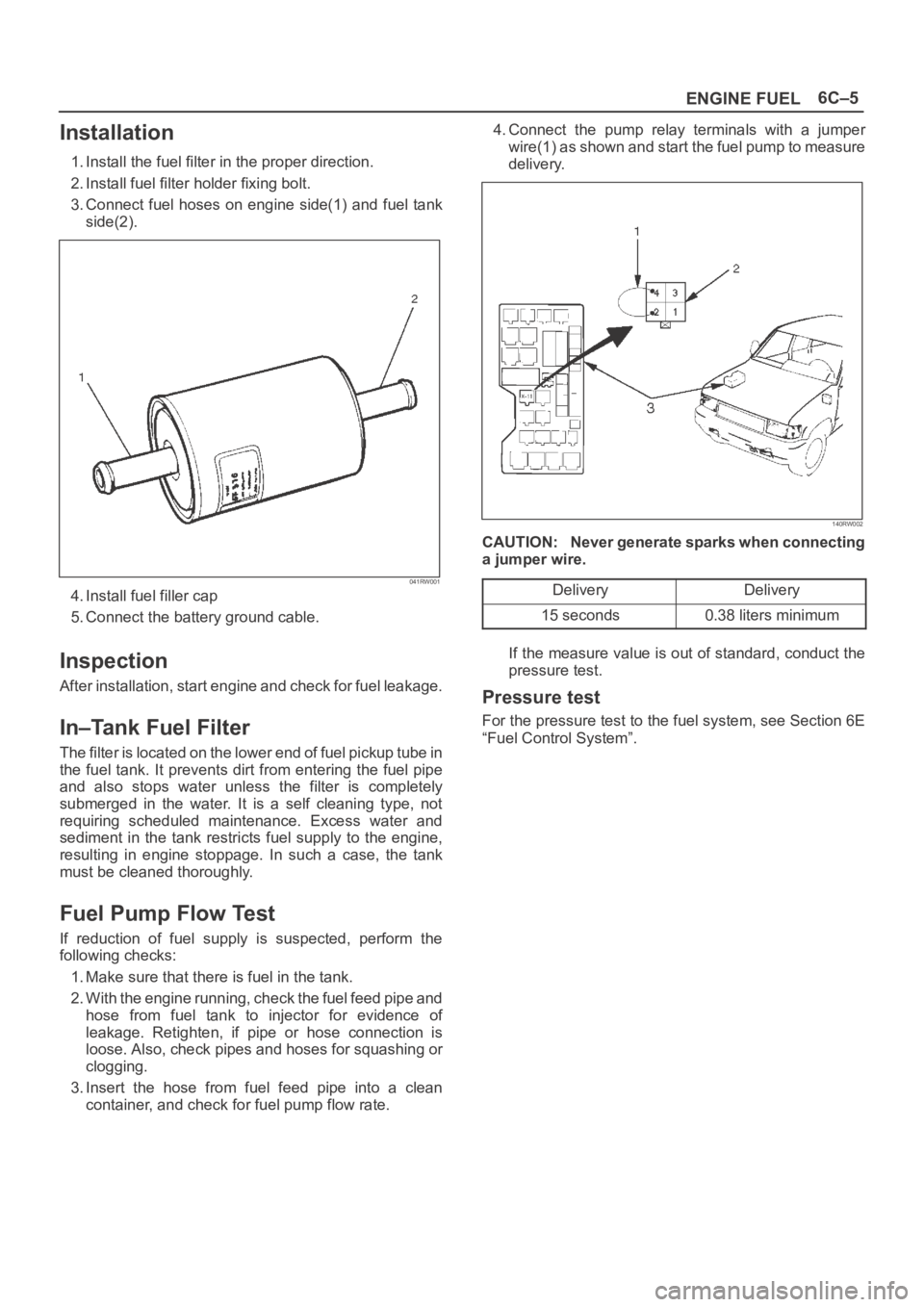
Installation
1. Install the fuel filter in the proper direction.
2. Install fuel filter holder fixing bolt.
3. Connect fuel hoses on engine side(1) and fuel tank
side(2).
041RW001
4. Install fuel filler cap
5. Connect the battery ground cable.
Inspection
After installation, start engine and check for fuel leakage.
In–Tank Fuel Filter
The filter is located on the lower end of fuel pickup tube in
the fuel tank. It prevents dirt from entering the fuel pipe
and also stops water unless the filter is completely
submerged in the water. It is a self cleaning type, not
requiring scheduled maintenance. Excess water and
sediment in the tank restricts fuel supply to the engine,
resulting in engine stoppage. In such a case, the tank
must be cleaned thoroughly.
Fuel Pump Flow Test
If reduction of fuel supply is suspected, perform the
following checks:
1. Make sure that there is fuel in the tank.
2. With the engine running, check the fuel feed pipe and
hose from fuel tank to injector for evidence of
leakage. Retighten, if pipe or hose connection is
loose. Also, check pipes and hoses for squashing or
clogging.
3. Insert the hose from fuel feed pipe into a clean
container, and check for fuel pump flow rate.4. Connect the pump relay terminals with a jumper
wire(1) as shown and start the fuel pump to measure
delivery.
140RW002
CAUTION: Never generate sparks when connecting
a jumper wire.
Delivery
Delivery
15 seconds0.38 liters minimum
If the measure value is out of standard, conduct the
pressure test.
Pressure test
For the pressure test to the fuel system, see Section 6E
“Fuel Control System”.
Page 4633 of 6000
6D3–2STARTING AND CHARGING SYSTEM
Starting System
General Description
Cranking Circuit
The cranking system consists of a battery, starter, starter
switch, starter relay, etc. These main components are
connected.
Starter
The cranking system employs a magnetic type reduction
starter in which the motor shaft is also used as a pinion
shaft. When the starter switch is turned on, the contacts of
magnetic switch are closed, and the armature rotates. At
the same time, the plunger is attracted, and the pinion is
pushed forward by the shift lever to mesh with the ring
gear.
Then, the ring gear runs to start the engine. When the
engine starts and the starter switch is turned off, the
plunger returns, the pinion is disengaged from the ring
gear, and the armature stops rotation. When the engine
speed is higher than the pinion, the pinion idles, so that
the armature is not driven.