check engine OPEL GT-R 1973 User Guide
[x] Cancel search | Manufacturer: OPEL, Model Year: 1973, Model line: GT-R, Model: OPEL GT-R 1973Pages: 625, PDF Size: 17.22 MB
Page 30 of 625
BATTERY AND CABLES - ALL MODELSlA- 9
plus 61 terminal of the voltage regulator and protects
the circuit to the generator telltale light.
BATTERY RECHARGING
There are two separate methods of recharging batter-
ies which giffer basically in the rate of charge. In the
slow-charge method, the battery is supplied a rela-
tively small amount of current for an extended
period of time. In the quick-charge method, the bat-
tery is supplied with a high current for a short period
of time.
Slow-Charging
Slow charking is the best and only method of com-
pletely ch+rging a battery. The slow-charge method,
properly applied, may be safely used under all possi-
ble conditions of the battery, provided electrolyte is at proper
wl in all cells. The battery may be fully
charged by this method, unless the battery is not
capable of taking a full charge. The normal slow
charging rate for the
12.volt battery is 5 amperes.
Full ch&e of battery is indicated when all cell spe-
cific gravities do not increase when checked at three
intervals
of one hour and all cells are gassing freely.
Due to the low rate during slow charging, plenty of
time must ,be allowed. Charge periods of 24 hours or
more are often required.
Quick-Charging
Since time!is often of most importance to the battery
owner, quick-charging must sometimes be used to
partially charge the battery so that the engine will
start and the owner can be on his way.
Charge at:50 amperes for 20 minutes (50 times 20
equals
100Q ampere minutes). If charger will not give
this rate, charge for an equal number of ampere mi-
nutes at the best rate available. Too high a current
during quick-charging will damage battery plates.
A battery cannot be brought up to a fully charged
condition
by the quick-charge method. The battery
can be substantially recharged or boosted, but in
order to bring the battery to a fully charged condi-
tion, the charging cycle must be finished by charging
at a low
oi normal rate. Some quick-chargers have
a
provisioA for finishing the charging cycle at a low
rate so
tha’t the battery can be brought up to a fully
charged condition.
Used
with:care, and employing all safeguards prov-
ided by the manufacturer, a quick-charger will not
damage a battery
which is in good condition.
BATTERY REMOVAL AND INSTALLATION
Removal
1. Disconnect battery cables (remove negative cable
first to prevent possible shorting).
2. Remove battery hold down
l&acket.
3. Remove battery.
Installation
‘1. Place battery back in hold down position.
2. Tighten hold down bracket bolts.
3. Connect battery cables (connect positive cable first
to prevent possible shorting).
FUSIBLE LINK REMOVAL AND INSTALLATION
Replace a burned out fusible link as follows:
1. Disconnect battery.
2. Disconnect connector eye on end of fusible link.
3. Cut off other end of burned out link, along with
solder joint.
4. Strip insulation from end of new fusible link and
from end of wiring harness so that each will slide into
soldering sleeve.
5. Crimp new link in soldering sleeve and solder
carefully.
6. Cover new connection tightly with electrical tape.
I. Install new link connector eye on other end of
fusible link.
A burned out fusible link connected to the starter
solenoid would be indicated by:
1. All electrical accessories dead.
2. Starter dead - will not even click. Even with a
nearly dead battery, the starter solenoid will
gener-
ally engage; therefore, no click means no solenoid
action, possibly due to a burned out fusible link.
SPECIFICATIONS
BATTERY SPECIFICATIONS
Delco-General 12 volt-44 amp hour storage battery
is installed as original equipment. Replace with a
Delco Energizer
Y55.
Page 31 of 625
1 B- 101973 OPEL SERVICE #MANUAL
STARTlhG SYSTEM
/
ALL
MODEILS
CONTENTS
Subject
DESCRIPTION AND OPERATION:
Starting SystemDescription
. . . . . . . . . . . . . . . . . . . . . . . . . . . . . . . . . . . . \
. . . . . .
DIAGNOSIS:
Starting System Diagnosis,
. . . . . . . . . . . . . . . . . , . . . . . . . . . . . . . . . . . . \
. . . . . . . .
MAINTENANCE AND ADJUSTMENTS:Starting System
Checks. . . . . . . . . . . . . . . . . . . . . . . . . . . . . . . . . . . . \
. . . . . . . . . . . . . .
MAJOR REPAIR:
Removal. . . . . . . . . . . . . . . . . . . . . . . . . . . . . . . . . . . . \
. . . . . . . . . . . . . . . . . ., . . . . . . . . . . . . . . . . . . . . . . . . . .
Disassembly. . . . . . . . . . . . . . . . . . . . . . . . . . . . . . . a.... . . . . . . . . . . . . . . . . . . . . . . . . . . . . . . . . . . . .\
CleaningandInspecting Parts. . . . . . . . . . . . . . . . . . . . . . . . . . . . . . . . . . . . \
. .
Replacing Field Coils. . . . . . . . . . . , . . . . . . . . . . . . . . . . . . . . . . . . \
. . . . . . . . . . . . . . . . . . . .
Checking and Replacing Brushes. . . . . . . . . . . . . . . . . . . . . . . . . . . . . . . .
Replacing Bushings. . . . . . . . . . . . . . . . . . . . . . . . . . . . . . . , . . . . \
. . . . . . . . . . . . . . . . . . . . . .
Assembly. . . . . . . . . . . . . . . . . . . . . . . . . . . . . . . . . . . . \
. . . . . . . . . . . . . . . . . . . . . . . . . . . . . . . . . . . . \
. . . . . .
Installation. . . . . . . . . . . . . . . . . . . . . . . . . . . . . . . . . . . . \
. . . . . . . . . . . . . . . . . . . . . . . . . . . . . . . . . . . . \
. . . .
SPECIFICATIONS:
Starter Specifications
. . . . , . , . . . . . . . . . . . . . . . . . . . . . . . . . . . . . . . . . . . . . . . . . . . . . . .
Page No.
lB-10
16-10
18-12
18-13
18-13
18-14
18-14
16-15
18-16
lB-16
18-17
18-17
DESCRIPTION AND OPERATION
STARTING SYSTEM DESCRlPTlqN
The new Delco Remy starter for 1973 is a brush-
type series wound electric motor equipped with an
overrunning clutch and operated by a
soienoid. The
field frame is enclosed by the commutator end frame
and the drive housing and carries the pole shoes and
the
field coils. The armature has a spline on the drive
end which carries the over-running clutch and pinion
assembly. The armature shaft is supported in
sin-
tered bronze bushings in the commtitator end frame
and the drive end housing. These bushings are
packed with lubricant during initial assembly
and
TROUBLE DIAGNOSIS ’
STARTING SYSTEM DIAGNOSIS/
require no additional lubrication between overhaul
periods.
As the starter is operated by turning the ignition
switch on the instrument panel, the shift lever is
moved against spring tension. By means of the guide
ring, the shift lever moves the pinion into mesh with
the flywheel ring gear.
After the pinion meshes with the flywheel ring gear
teeth, the solenoid contact disc closes the circuit and
the engine is cranked. When the engine starts, the
speed of the rotating flywheel causes the pinion to
over-run the clutch and armature. The pinion con-
tinues to be engaged as long as the shift lever is kept
in the cranking position.
In case of cranking motor breakdown, it should be kept in mind that the
relevant cause(s) for the trouble may not only lie in the cranking mot\
or itself
Page 33 of 625
19- 12 1973 OPEL SERVICE MANUAL :ConditionPosiible CauseCorrection4. Voltage drop.1. Check wiring and wiring
connections.
5. Overrun&g clutch slips.1. Replace overrunning clutch.
The cranking motor keeps
on rotating after ignition
switch is off.1. Ignition
{witch does not
cut off or solenoid switch
sticks.
1, Immediately disconnect cranking
motor cable from battery. Inspect
and/or replace or repair ignition and
solenoid switches as required.
The drive pinion does notdemesh after engine has
been cranked.1. Drive pinion or ring gear
1. Clean components as specified.
teeth clogged or flattened.Replace as required.
Return spring slack or broken.MAlNTEilANCE AND ADJUSTMENT
/
STARTING SYSTEM CHECKS
Voltage Loss ChecksWhen the starter cranks too slowly, check the bat-
tery state of charge and all electrical connections
between the battery and starter.
1. Turn on headlights and
opera’te starter. If head-
lights dim considerably when starter is engaged, the
battery may be discharged or be defective. Check the
battery.
2. If the headlights stay bright but the starter d&s
not turn over, the starter cables may be faulty or the
starter defective.
(a) Test battery voltage while cranking engine
1(9volts minimum).
(b) Check voltage from starter tkrminal of solenoid
to starter frame while cranking engine.
3. The difference in readings taken in Operations 2a
and 2b above represents the
volt& drop through the
cables and solenoid switch. Voltdge drop should
Gotexceed
.5 volt.
4. Locate excessive resistance as follows:
(a) Turn voltmeter to scale above 12 volts and con-
nect voltmeter leads
across connection or switch: to
be checked.
(b) With starter switch closed, turn voltmeter switch
to lowest scale and take reading as quickly as possi-
ble, then turn switch back to higher scale and stop
cranking engine.(c) Voltmeter must not read more than
.2 volt across
any
c:onnection. If voltmeter reads more than .2 volt,
the
d~efect must be corrected.
Starter Current Draw - Lock Test1. Make sure battery is fully charged and in good
condition.
2. Connect a volt ampere starter tester according to
manufacturer’s instructions.
3. Pull parking brake on securely, shift transmission
into 4th (direct) gear and actuate starter. (Starter will
not
t,urn engine because engine is locked through
transmission.)
4. While starter is actuated, read voltage and current.
Refer to Specification Chart.
(a) Voltage low
_ poor battery or a voltage loss in the
starter circuit.
(b) Current high
- short circuit in starter. Overhaul
starter.
(c) Current low
- commutator dirty, brushes worn,
solenoid switch contacts defective or open circuit in
starter. Overhaul starter.
Starter Current Draw. On Car1. Bring engine to normal operating temperature.
2. Stop engine and disconnect coil wire from dis-
tributor.
3. Ground coil wire to prevent excessive coil voltage
build up.
Page 38 of 625
STARTING SYSTEMlB- 17
7. Seal area between solenoid and frame. See FigurelB-17.
8. With brushes and spring in housings held in place
with a 29 @llimeter socket, slide frame assembly in
position.
9. Install i+ulating sleeves in field frame.
10. Install knd frame and replace through bolts and
tighten bolts.
11. Install bolt holding field frame to solenoid.
SPEClFltjATlONS
Starter SpecificationsStarterNumber. . . .
.._.._..._...........................RatedVoltage
. . . . . . . . . . . . . . . . . . . . . . . . .No voad Test:
...............................................EF 12V0 .8 PS
.....................................................................12Volts
................................................................................................................................10.6Amperes
........................................................................................................................30-50RPM
......................................................................................................................7300-8500Cranking Amperes Test (InCar-Engine atOperating Temp.)
..................................175-205
Lock Test:
Volts
............................................................................................................................6 Min.
Amperes
....................................................................................................................280-320Volt$geRequiredtoCloseSolenoidContacts
....................................................................7.5MinimumDiameterof Commutatorin
Inches................................................................1.46Brush Spring Pressure in Ounces
....................................................................................40-46Minimum Length of Brushes in Inches...............................................................................2812. Check starter on bench before installing.
Starter Installation
1. Hold starter in position.
2. Install two bolts, one nut and lockwashers.
Tighten securely.
3. Install support bracket. To ensure a stress-freeintitallation, install bolt and two nuts only finger
tight. First tighten the bolt at the engine, then tighten
the two nuts at the starter end frame.
Page 39 of 625
1 C- 18 1973 OPEL SERVICE MANUAL
IGNITIPN SYSTEM
CbNTENTS
Subject
DESCRIPTION AND OPERATION: Ignition System ..................................................................
Ignition
Switc,h....................................................................
Ignition Coil
..........................................................................\
Distributor
............................I...............................................
DIAGNOSIS: (Not Available)
MAINTENANCE AND ADJUSTMENTS: Contact PointReplacement ............................................
Dwell Angle Adjustment :
................................................
Ignition Timing Adjustment ..........................................
Ignition Wire Inspection :
..................................................
Check Ignition Output ......................................................
Check Distributor
..............................................................
Check Spark Plugs
............................................................
MAJOR REPAIR: Distributor Removal ..........................................................
Disassembly ........................
I...............................................
Reassembly
..........................I...............................................
Distributor Installation
....................................................
SPECIFICATIONS: /
Ignition
Coil ..........................................................................
Distributor
....‘........................i...............................................
Spark Plugs ........................................................................\
..
DESCRIPTION AND OPERATION
INGITION SYSTEM
The ignition system basically consists of an ignitipn
switch, ignition coil, distributor, battery and related
wiring. The ignition switch is located in the steering
column, the ignition coil is located left front inner fender
skirt and the distributor is located at the left
front of the engine.
IGNITION SWITCH
The combined ignition switch and steering lock ian
be switched to any one of the below listed positions.
Insert key with notch pointing upward.
Page No.
lC-18
lC-18
lC-19
lC-19
1 c-20
1 c-20
1 c-20
lC-21 r
lC-21
1 c-22
1 c-22
1 r-23
1 C-23
1 c-24
1 C-25
1 C-26
1 C-26
1 C-26
(Fully counterclockwise) Lock position. Ignition
locked, steering locked, only with key removed.
Electrical circuits disconnected except to main light-
ing switch and dome lamp. The
key can be removed.
0- (First position clockwise from lock) Garage posi-
tion. ‘The key and lock assembly must be pushed “in”
to reach this position from lock. The steering is un-
locked and the ignition is off. The electrical circuits
are the same as in lock position. The key cannot be withdrawn.
l- [Chposition.) All electrical circuits controlled by
ignition switch are completed through the switch.
The key cannot
be removed while switch is in drive
position.
Page 41 of 625
I
ilC- 201973 OPEL SERVICE MANUAL
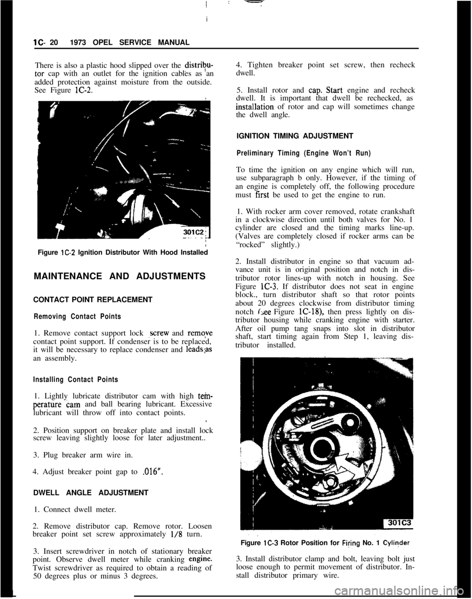
There is also a plastic hood slipped over the distrivu-tar cap with an outlet for the ignition cables as an
added protection against moisture from the outside.
See Figure lC-2.
Figure lC-2 Ignition Distributor With Hood Installed
MAINTENANCE AND ADJUSTMENTS
CONTACT POINT REPLACEMENT
Removing Contact Points1. Remove contact support lock
,screw and remqve
contact point support. If condenser is to be replaced,
it will be necessary to replace condenser and
1eads;asan assembly.
Installing Contact Points1. Lightly lubricate distributor cam with high tein-perature cam and ball bearing lubricant. Excessive
lubricant will throw off into contact points.
:
,
2. Position support on breaker plate and install lock
screw leaving slightly loose for later adjustment..
3. Plug breaker arm wire in.
4. Adjust breaker point gap to ,016”.
/
DWELL ANGLE ADJUSTMENT
1. Connect dwell meter.
2. Remove distributor cap. Remove rotor. Loosen
breaker point set screw approximately
l/8 turn.
3. Insert screwdriver in notch of stationary breaker
point. Observe dwell meter while cranking engine.
Twist screwdriver as required to obtain a reading of
50 degrees plus or minus 3 degrees.4. Tighten breaker point set screw, then recheck
dwell.
5. Install rotor and cap.~Start engine and recheck
dwell. It is important that dwell be rechecked, as
instal~lation of rotor and cap will sometimes change
the dwell angle.
IGNITION TIMING ADJUSTMENT
Preliminary Timing (Engine Won’t Run)To time the ignition on any engine which will run,
use subparagraph b only. However, if the timing of
an engine is completely off, the following procedure
must first be used to get the engine to run.
1. With rocker arm cover removed, rotate crankshaft
in a clockwise direction until both valves for No. 1
cylinder are closed and the timing marks line-up.
(Valves are completely closed if rocker arms can be
“rocked” slightly.)
2. Install distributor in engine so that vacuum ad-
vance unit is in original position and notch in dis-
tributor rotor lines-up with notch in housing. See
Figure lC-3. If distributor does not seat in engine
block., turn distributor shaft so that rotor points
about 20 degrees clockwise from distributor timing
notch
(see Figure lC-18), then press lightly on dis-
tributor housing while cranking engine with starter.
After oil pump tang snaps into slot in distributor
shaft, start timing again from Step 1, leaving dis-
tributor installed.
Figure lC-3 Rotor Position for Filing No. 1 Cyliqder
3. Install distributor clamp and bolt, leaving bolt just
loose enough to permit movement of distributor. In-
stall distributor primary wire.L
Page 42 of 625
IGNITION SYSTEMlC-214. Rota&distributor counterclockwise slightly until
contact pbints just start to open. This must be done
very carefully or engine will not start.
5. Install distributor cap. Make sure spark plug wires
are correctly installed in distributor cap, through clip
and on spark plugs.
Finish TimingIContact boint gap
(.016” at widest gap) or dwell 50
degrees plus or minus 3 degrees should always be
checked before adjusting ignition timing.
1. Connekt timing light to No. 1 spark plug.
2. Disconnect and plug vacuum advance unit and
retard u$it hoses.
3. Connect a tachometer from distributor side of coil
to
groun$l.4. Start dngine. Set idle speed to 900 RPM.
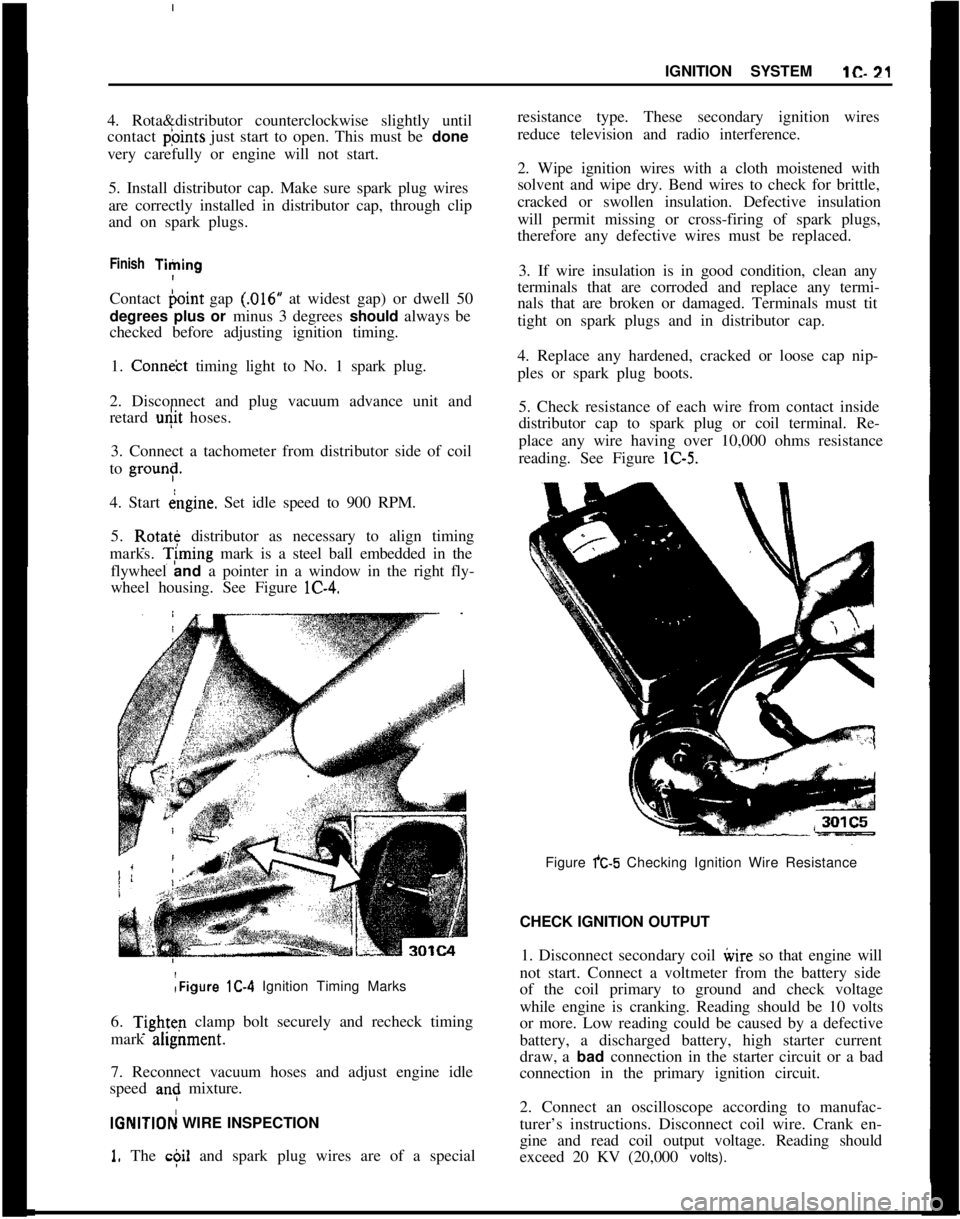
5. Rotate distributor as necessary to align timing
marks. T;ming mark is a steel ball embedded in the
flywheel and a pointer in a window in the right fly-
wheel housing. See Figure lC-4.:Figure lC-4 Ignition Timing Marks
6.
Tightq clamp bolt securely and recheck timing
mark ahgnment.
7. Reconnect vacuum hoses and adjust engine idle
speed
an: mixture.
IGNlTlOFj WIRE INSPECTION
1. The c$il and spark plug wires are of a specialresistance type. These secondary ignition wires
reduce television and radio interference.
2. Wipe ignition wires with a cloth moistened with
solvent and wipe dry. Bend wires to check for brittle,
cracked or swollen insulation. Defective insulation
will permit missing or cross-firing of spark plugs,
therefore any defective wires must be replaced.
3. If wire insulation is in good condition, clean any
terminals that are corroded and replace any termi-
nals that are broken or damaged. Terminals must tit
tight on spark plugs and in distributor cap.
4. Replace any hardened, cracked or loose cap nip-
ples or spark plug boots.
5. Check resistance of each wire from contact inside
distributor cap to spark plug or coil terminal. Re-
place any wire having over 10,000 ohms resistance
reading. See Figure lC-5.
Figure fC-5 Checking Ignition Wire Resistance
CHECK IGNITION OUTPUT
1. Disconnect secondary coil ivire so that engine will
not start. Connect a voltmeter from the battery side
of the coil primary to ground and check voltage
while engine is cranking. Reading should be 10 volts
or more. Low reading could be caused by a defective
battery, a discharged battery, high starter current
draw, a bad connection in the starter circuit or a bad
connection in the primary ignition circuit.
2. Connect an oscilloscope according to manufac-
turer’s instructions. Disconnect coil wire. Crank en-
gine and read coil output voltage. Reading should
exceed 20 KV (20,000 volts).
Page 43 of 625
lC- 22 1973 OPEL SERVICE MANUAL j
3. Start engine and disconnect a wire from a spark
plug. Read output voltage of disconnected spark
plug circuit. Reading should exceed 20 KV
(20,poO
volts).I
CHECK DISTRIBUTOR
!1. Clean distributor cap and inspect it for cracks or
tracking. Inspect inner segments for erosion and
outer sockets for corrosion.
2. Clean and inspect ignition wires. Make sure resist-
ance of each wire is less than 10,000 ohms. Replace
any defective spark plug boots or distributor
capnipples. See paragraph lC-12.
3. Inspect breaker points and replace if necessary.
Adjust breaker point gap to
,016 inch with rubbing
block on peak of cam lobe or check dwell and adjust
if not 50 degrees plus or minus 3 degrees. 4. Check
dwell variation by reading dwell at idle and at 3000
RPM. Dwell must not vary more than 3 degrees.
Excessive variation means distributor shaft, cam or
breaker plate are worn or damaged--overhaul dis-
tributor and replace defective parts.
5. Check distributor condenser for a minimum series
resistance and insulation leakage. Check for a
capacity between
.15 and .20 microfarads.
6. Check total advance (centrifugal and vacuum) at
2500 engine RPM using a timing light having a dial
for reading advance.
(a) The timing marks are aligned with both the
vacuum advance and the vacuum retard hoses dis-
connected and plugged.
Engine idle should be 900 RPM.
(b) Reconnect vacuum hoses. Run engine at
3600RPM and adjust knob until timing marks are
aligned. Read advance on dial. Maximum centrifugal
advance should be between 28-32 degrees.
7. If total advance is out of specifications, check
centrifugal advance only, at
2500 RPM. Discon+ectand plug all vacuum hoses. Maximum vacuum ad-
vance should be l-5 degrees at 4.5-5.0 in. hg.
8. Replace centrifugal or vacuum advance parts as
required to bring distributor total advance within
specifications.
9. Check operation of vacuum retard unit (rear unit)
by first making sure timing marks are aligned with
vacuum hoses disconnected and at slow idle (700
RPM). Then connect vacuum hose to vacuum retard
unit (rear unit). Timing ball should move in a retard
direction (upward).
CHEICK SPARK PLUGS1. Remove spark plugs. If electrodes are badly worn,
discard plugs. If inner or outer porcelain is cracked
or broken, discard plugs.
2. Note color and general appearance of inner end of
spark plug. Brown to grayish
- tan deposits and slight
electrode wear indicate correct spark plug heat
range. Plugs having this appearance may be cleaned,
regapped, tested and reinstalled.
3. Clean spark plugs in a sand blast type cleaner.
Clean only enough to remove deposits, not enough to
wear away porcelain. If deposits are too hard to
remove or if porcelain is glazed, discard plugs.
4. After cleaning spark plugs, clean tiring surfaces of
electrodes with a line file.
5. Test cleaned spark plugs on a pressure tester by
comparing spark of the used plugs with that of a new
plug. Install tested plugs, using new gaskets.
6. If removed spark plugs have excessive carbon foul-
ing and if the car will be driven mostly at low speeds
in city driving, it is advisable to replace plugs with
a hotter plug, AC43FS.
7. If removed plugs show rapid electrode wear or
inner porcelain breakage at low mileage. Check for
a vacuum leak such as a poor manifold to head fit.
8.
Clap spark plugs carefully (new or cleaned) using
a
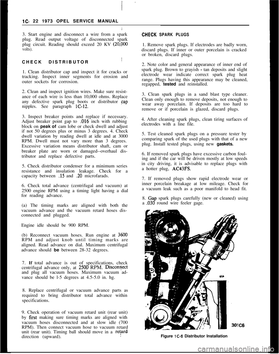
,030 round wire feeler gage.IC6
Figure lC-6 Distributor Installation
Page 51 of 625
i
1 D- 301973 OPEL SERVICE MANUAL
6. Make sure all electrical accessories are turned (lff.
Start engine with battery post adapter switch closed;
open switch as soon as engine
iS: started.
7. Adjust engine speed to 2500 RPM.
8. Turn tester control knob to “LOAD” position
aid
adjust knob to obtain highest possible ammeter r&d-
ing. Output must be 30 amperes minimum. If
outcut
is okay, proceed to voltage regulator test below. j
/.9. If output is low, defect may be in alternator or m
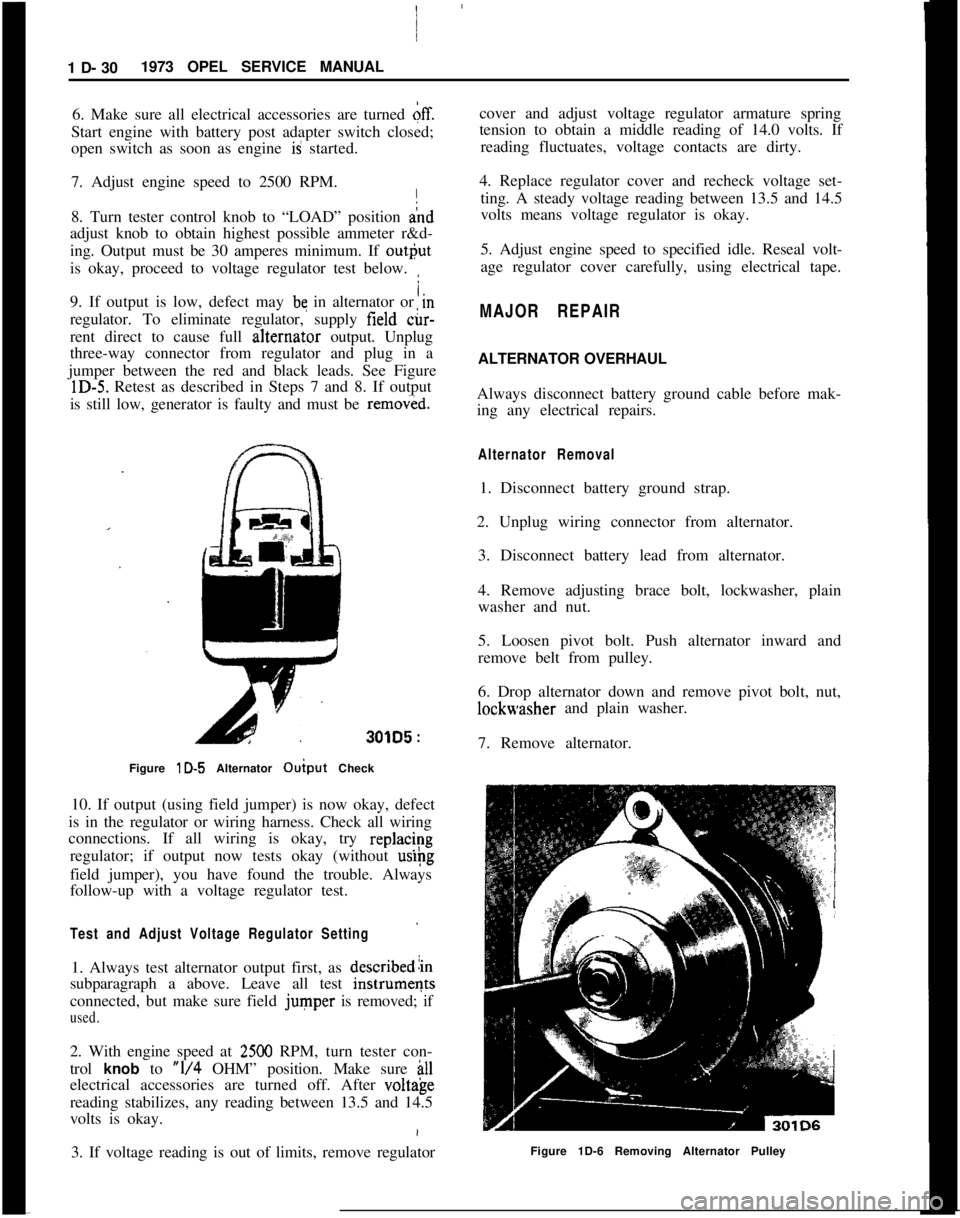
regulator. To eliminate regulator, supply field &-
rent direct to cause full alternat,or output. Unplug
three-way connector from regulator and plug in a
jumper between the red and black leads. See Figure
lD-5. Retest as described in Steps 7 and 8. If output
is still low, generator is faulty and must be
remov&d.
301D5 :
Figure lD-5 Alternator Ouiput Check I
10. If output (using field jumper) is now okay, defect
is in the regulator or wiring harness. Check all wiring
connections. If all wiring is okay, try
replac/~g
regulator; if output now tests okay (without
uslpg
field jumper), you have found the trouble. Always
follow-up with a voltage regulator test.
Test and Adjust Voltage Regulator Setting
1. Always test alternator output first, as describedlin
subparagraph a above. Leave all test
instrumeqts
connected, but make sure field
jumper is removed; if
used.
2. With engine speed at 2500 RPM, turn tester con-
trol
knob to “l/4 OHM” position. Make sure ill
electrical accessories are turned off. After volt&e
reading stabilizes, any reading between 13.5 and 14.5
volts is okay.
3. If voltage reading is out of limits, remove regulator cover and adjust voltage regulator armature spring
tension to obtain a middle reading of 14.0 volts. If
reading fluctuates, voltage contacts are dirty.
4. Replace regulator cover and recheck voltage set- ting. A steady voltage reading between 13.5 and 14.5
volts means voltage regulator is okay.
5. Adjust engine speed to specified idle. Reseal volt-
age regulator cover carefully, using electrical tape.
MAJOR REPAIR
ALTERNATOR OVERHAUL
Always disconnect battery ground cable before mak-
ing any electrical repairs.
Alternator Removal
1. Disconnect battery ground strap.
2. Unplug wiring connector from alternator. 3. Disconnect battery lead from alternator.
4. Remove adjusting brace bolt, lockwasher, plain
washer and nut.
5. Loosen pivot bolt. Push alternator inward and
remove belt from pulley.
6. Drop alternator down and remove pivot bolt, nut,
lockwasher and plain washer.
7. Remove alternator.
Figure 1D-6 Removing Alternator Pulley
Page 88 of 625
I
GAUGES1 I- 67I
I Condition
Car
&s out of gas with
gauge indicating fuel in
tank. 1
I
I
I
I
IPossible Cause
1. Tank unit misadjusted
2. Defective voltage
stabilizer.Correction
1. Follow corrective action as
stated above (obtain empty
reading on dash)
1. See corrective action above.
Temperature gauge not1. Loose dash gauge1. See corrective action above.
Iattaching nut.
I
I
I2. Defective temperature1. Install 40 ohm resistor
Isending unitbetween temperature sneding
Iunit and ground (disconnect
I
from unit). If dash unit reads
I
full scale, replace temperature
Isending unit.
I
I
I3. Open wiring.1. Follow corrective action as
Istated above (connector socket
Iwith blue wire).Tempkrature gauge indicates
hot when engine temperature1. Incorrect temperature1. Check for correct sending unit
sending unit
normal.(white porcelain) replace if
incorrect.
2. i>efective temperaturesending unit.1. See corrective action above.
3. Dkfective voltage
stabilizer.
1. See Corrective action above.
GAS
GdUGE TROUBLE DIAGNOSIS - GT4. Disconnect the tank unit lead wire (light blue with
black tracer) from the tank unit.
An inoperative gas gauge reading can normally be
found to result from a poor grounding condition
within the circuit. Using the procedure as outlined
below may lead to the correction of the inoperative
reading without replacement of either the tank unit
or the
dph unit.5. Connect ihe stock tank unit; ground unit, and
operate manually.
6. If the dash unit shows a correct reading, then
replacement of the tank unit is required as the cor-
rection.
1. Makelcertain the gas tank (ground) strap is prop-
erly secured.A correct reading will be one which resembles the
movement of the manually-operated tank unit.
2. Make’certain the ground wire (brown in color) for
gasoline/ and temperature gauges is properly con-
nected tb the windshield wiper motor and is secured.
(This
gl?ound wire is also common for the heater
blower
etor.)7. If the dash unit does not show a correct reading,
then its replacement is necessary.
If the adove procedure does not produce a satisfac-
tory gaube reading, an attempt to isolate the defec-
tive
par<, i.e. tank or dash unit should be made.
3. Rem&e a tank unit from parts stock.MAJOR
AEPAIR
OPEL 1900. MANTA
Removing Voltage Stabilizer1. Remove instrument cluster housing assembly.