transmission OPEL GT-R 1973 User Guide
[x] Cancel search | Manufacturer: OPEL, Model Year: 1973, Model line: GT-R, Model: OPEL GT-R 1973Pages: 625, PDF Size: 17.22 MB
Page 60 of 625

WINDSHIELD WIPERSlE- 39
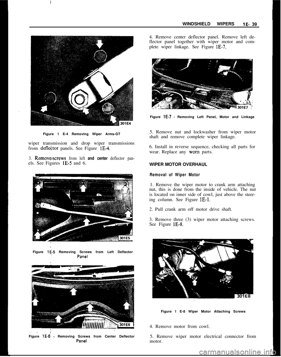
Figure 1 E-4 Removing Wiper Arms-GT
wiper transmission and drop wiper transmissions
from defleCtor panels. See Figure lE-4.3. Remowscrews from left and center deflector pan-els. See Figures lE-5 and 6.
Figure
l$-5 Removing Screws from Left Deflector
I
Pa%?1
. .;Figure
lE-6 - Removing Screws from Center Deflector
Pall-Z!14. Remove center deflector panel. Remove left de-
flector panel together with wiper motor and com-
plete wiper linkage. See Figure lE-7.
Figure
lE-7 - Removing Left Panel, Motor and Linkage
5. Remove nut and lockwasher from wiper motor
shaft and remove complete wiper linkage.
6. Install in reverse sequence, checking all parts for
wear. Replace any worn parts.
WIPER MOTOR OVERHAUL
Removal of Wiper Motor1. Remove the wiper motor to crank arm attaching
nut, this is done from the inside of vehicle. The nut
is located on inner side of cowl, just above the steer-
ing column. See Figure lE-1.
2. Pull crank arm off motor drive shaft.
3. Remove three (3) wiper motor attaching screws.
See Figure lE-8.
Figure 1 E-8 Wiper Motor Attaching Screws
4. Remove motor from cowl.
5. Remove wiper motor electrical connector from
motor.
Page 61 of 625

1 E- 40 1973 OPEL SERVICE MANUALDisassemblyI
1. Remove two (2) motor housing attaching
screw$(Item No. 4) and two (2) angle brackets (Item No.
3). See Figure lE-9.
Figure 1 E-S Removing Motor Housing Attaching
SCFS”JSFigure
1 E-l 0 Transmission and Armature Removed
from Motor Housing2. Remoyz transmission housing together with arma-
ture from motor housing. See Figure lE-10. It may
be necessary to hold armature in transmission hous-
ing with a screw driver.
3.
Rem~ove armature from transmission housing.
4. Remove five (5) transmission housing cover
screws. See Figure lE-11.Figure 1 E-l 1 Remove Transmission Housing CoverSCEWS
5. Remove cover, gasket and driven gear from trans-
mission housing. See Figure IE-12. Remove pivot
ball from driven gear. See Figure lE-15.
Figure 1 E-l 2 Remove Driven Gear
6. If required, remove brushes.
a. To remove positive brushes, cut brush leads off at
brush holder. See Figure lE-13.
b. To remove negative brush, remove brush retaining
screw from commutator end frame. See Figure
lE-
14.
Page 62 of 625

WINDSHIELD WIPERSlE-41
Figurk 1 E-l 3 Cut Off Positive Brush Leads
i
Figure iE-14 Remove Negative Brush Retaining
S.X?WI
Cleaning apd Inspection of PartsWith the ekception of electrical parts and bushings,
clean all components in a cleaning solvent.
1. Check irmatare windings for ground, or open
circuit. If
b ground or open circuit is evident, the
armature must be replaced. If the armature checks
out, the c
brushes should be 6.35 to 8.47 ounces. Spring pres-
sure of worn brushes should be at least 3.5 ounces.
In case of /ower spring pressure, replace springs.
3. Check blushes for wear and replace if necessary.
Minimum brush length should be
.24’inch.4. Check d$ven gear for wear and replace if neces-
sary.
Assembly
02383. I
2. Install
d&en gear into housing3. Apply a small amount of grease to ball cavity of
driven gear and insert ball. See Figure lE-15.
Figure lE-15 Insert Ball into Driven Gear
4. Install transmission housing cover. See Figure
lE-
16.2. DRIVEN GEAR
3. CONTACT SPRINGS
4. TRANSMISSION
HOUSING COVER
Figure 1 E-l 6 Install Transmission Housing
Cover5. Solder positive brush lead(s) to brush holder(s).
Hold brush lead with needle nose pliers to prevent
solder from running up wire strands. See Figure
lE-
17.6. Install negative brush
7. Apply a small amount of grease to end of armature
shaft. Lightly oil armature shaft.
8. Insert brush springs and brushes into brush hold-
ers. Slide armature into housing, taking care not to
damage brushes.
Page 65 of 625

1 E- 44 1973 OPEL SERVICE MANUAL)
‘30
1.2.
3.4.
5.
6.
7.
8.
9.
10.
11.
12.
13.
14.
15.ATTACHING SCREWS16. NEGATIVE BRUSH
TRANSMISSION COVER 17. ATTACHING SCREW
HEX. NUT
THREADED END ~18. RETAiNING PLATE
19. POSlilVE BRUSH
PLAY PIN20. WIRE’
GASKET21. THRUST SPRING
BALL22. RUBBFR MOUNTS
DRIVEN GEAR23. ARMATURE
WASHER24. ATTACHING SCREWS
THREADED END25. LOCKWASHER
PLAY PIN26. ANGLE BRACKE’TS
SLEEVE27. MOTOR HOUSING
MOUNTING PLATE28. MAGNET RING
GASKET29. MAGNET THREADED
TOOTHED WASHERSPi N
LOCATORSATTACHING SCREWS30. NORTH POLE PAINT
TRANSMISSIONMARKING ON
HOUSING
THISfSIDENOTE: MOTOR HOUSING
WITH MAGNET RING HAS
TO BE INSTALLED SO THAT
THE NORTH POLE MARKING
(PAINT DOT ON MAGNET
RING) FACES TOWARDS
‘IRANSMISSION.
301 E20Figure 1620 Wi$er Motor
- Exploded View
Page 76 of 625

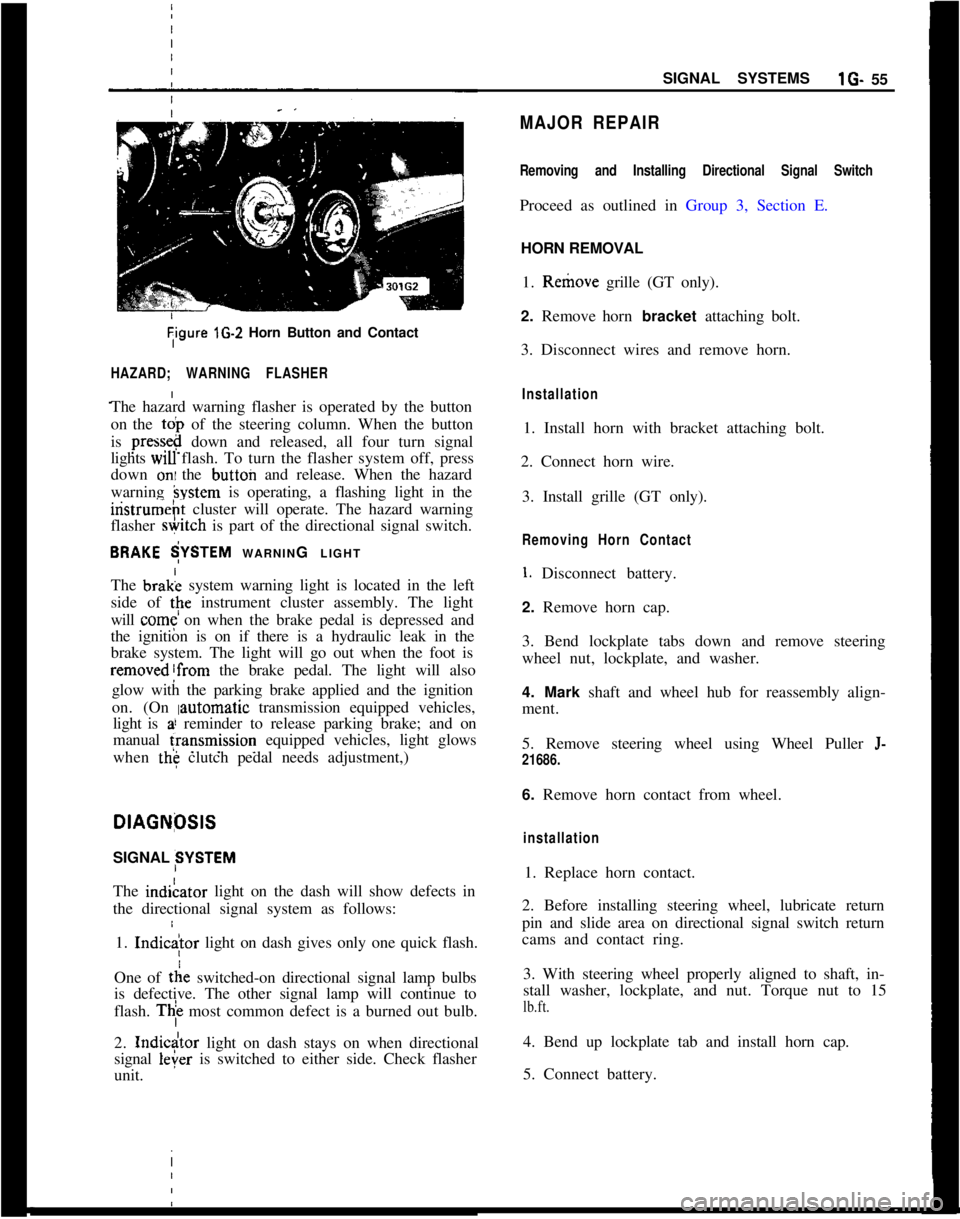
Tigure lG-2 Horn Button and Contact
HAZARD; WARNING FLASHER
The hazard warning flasher is operated by the button
on the
toi, of the steering column. When the button
is
press&@ down and released, all four turn signal
lights
WIU flash. To turn the flasher system off, press
down
oni the button and release. When the hazard
warning
hystem is operating, a flashing light in the
iristrumeht cluster will operate. The hazard warning
flasher
&itch is part of the directional signal switch.
BRAKE $YSTEM WARNING LIGHT
The brak; system warning light is located in the left
side of
tpe instrument cluster assembly. The light
will
come on when the brake pedal is depressed and
the ignition is on if there is a hydraulic leak in the
brake system. The light will go out when the foot is
removed!from the brake pedal. The light will also
glow with the parking brake applied and the ignition
on. (On
Iautomatic transmission equipped vehicles,
light is
a! reminder to release parking brake; and on
manual
fransmission equipped vehicles, light glows
when
the clutch pedal needs adjustment,)
I
DlAGNfXlS
SIGNAL SYSTEM
The indiLator light on the dash will show defects in
the directional signal system as follows:
1.
Indic
tie switched-on directional signal lamp bulbs
is defective. The other signal lamp will continue to
flash.
Thi most common defect is a burned out bulb.
2.
Indicdtor light on dash stays on when directional
signal
leier is switched to either side. Check flasher
unit. I
SIGNAL SYSTEMSlG- 55
MAJOR REPAIR
Removing and Installing Directional Signal Switch
Proceed as outlined in Group 3, Section E.
HORN REMOVAL
1. Remove grille (GT only).
2. Remove horn bracket attaching bolt.
3. Disconnect wires and remove horn.
Installation
1. Install horn with bracket attaching bolt.
2. Connect horn wire.
3. Install grille (GT only).
Removing Horn Contact
1. Disconnect battery.
2. Remove horn cap.
3. Bend lockplate tabs down and remove steering
wheel nut, lockplate, and washer.
4. Mark shaft and wheel hub for reassembly align-
ment.
5. Remove steering wheel using Wheel Puller
J-
21686.
6. Remove horn contact from wheel.
installation
1. Replace horn contact.
2. Before installing steering wheel, lubricate return
pin and slide area on directional signal switch return
cams and contact ring.
3. With steering wheel properly aligned to shaft, in-
stall washer, lockplate, and nut. Torque nut to 15
lb.ft.
4. Bend up lockplate tab and install horn cap.
5. Connect battery.
Page 93 of 625

1 J- 72 1973 OPEL SERVICE MANUAL
I
WIRING IDIAGRAMS
CONTENTS
Subject
1973 WIRING DIAGRAMS: Windshield Wiper and
Horn:- Opel 1900 -
Manta....................................I.............. ..............................
Windshield Wiper and Horn’- Rallye ..........................
Windshield Wiper
andHorn!-GT
..................................
Turn Signal and Hazard Flasher
-
Opel 1900 - Manta !
........................................................
Turn Signal and Hazard Flasher
- GT ..........................
Oil, Fuel,
Temp.: Tach, Stop and Brake
Warning Light
.GT........................................................
Blower Motor, Lighter and
Rackup Lights -
Qpel 1900.Manta ........................................................
Blower Motor and Lighter
.,GT....................................
Indicator Lights and Gauges
- Opel 1900 -
Manta ........................................................................\
........
Indicator Lights
andGauges.Rallye ..........................
Dome Light and Buzzer
- Opel 1900 - Manta..........
Dome Light, Buzzer and Clock - GT ............................
Headlamps
- Opel 1900 ’
....................................................
Headlamps
.Mantaj............................................................
Headlamps and Fog Lights
.Rallye ..............................
Headlamps, Parking, Tail and Instrument
PanelLighting.GT ........................................................
Left Parking and Tail Lights
- Opel 1900 -
Manta ..................................i.............................................
Right Parking and Tail Lights
- Opel 1900 -
Manta................. ..*............................................................
Starting, Ignition and Charging
-
Opel 1900.Manta..........i.............................................
Starting, Ignition and Charging
- GT ..........................
Instrument
Panel.GT ......................................................
A/C Generatorand Regulator
- All Models..............
Seat Belt Warning System (Manual Transmission)
-Opel1909-Manta ..........................
Seat Belt Warning System (Automatic Transmission)
.Opel 1900 - Manta..........................
Seat Belt Warning System (Manual Transmission)
- GT........................................................ Page No.
1 J-74
1 J-75
1 J-76
1 J-77
1 J-78
1 J-79
1 J-80
lJ-81
1 J-82
1 J-83
1 J-84
1 J-85
1 J-86
1 J-87
1 J-88
1 J-89
1 J-90
1 J-91
1 J-92
1 J-93
1 J-94
1 J-95
1 J-96
1 J-97
1 J-98
Page 94 of 625

I
/WIRING DIAGRAMS13-73ISeat Belt Warning System (Automatic
Page No.Transmission)
.GT.......................................................lJ-99HeatedRear Glass
.Opel1900.Manta...................15-100Heated Rear Glass
.GT..................................................*,lJ-101Opel 1900 Color Schematic.........................................
lJ-103Manta
ColorSchematic.................................................1 J-105GT
ColorSchematic
.........................................................1 J-107
Page 118 of 625

WIRING DIAGRAMSlJ- 97
cI
&N
/I
IFigure 1 J-24 Seat Belt Warning System (Automatic Transmission) Opel 1900 Manta
Page 120 of 625

WIRING DIAGRAMSlJ-99Figure
lJ-26 Seat Belt Warning System (Automatic Transmissionl - GT
Page 171 of 625

3A- 41973 OPEL SERVICE MANUAL
The two cross-members to body supports are at-
tached to the horizontal part of the cross-member
with two bolts. The oufererbolt serves simultaneously
as support for the lower control arm. As the bolt is
inserted from the front, the cross-member to body
support can be removed without the lower control
arm. The inner bolt attaches simultaneously to the
steering.
The stabilizer is U-shaped and supported in rubber
bushings in the two cross-members to body supports.
The complete front suspension is attached to the
underbody in four places.
The engine damper blocks are bolted to the inside of
the inclined parts of the cross-member.
The front wheel bearings are roller bearings.
All front suspension joints are maintenance-free.
MAINTENANCE AND ADJUSTMENTSFRONT WHEEL BEARING ADJUSTMENT
1. If wheel has not previously been removed from the
car, remove grease cap, cotter pin, and spindle nut.
Discard cotter pin.
2. Torque spindle nut to 18
lb.ft. while rotating
wheel. This will allow the bearings to settle.
3. Back offspindle nut
l/4 turn. If slot and cotter pin
hole are staggered, further back off nut
l/l2 turn,
but do not tighten, until next slot in nut is in align-
ment with hole in spindle. Install new cotter pin. A
properly adjusted wheel bearing has a small amount
of end play and a loose nut when adjusted in the
above manner.
MAJOR REPAIRREMOVAL AND INSTALLATION OF FRONT
SUSPENSION
(COMPLETE ASSEMBLY)
Removal GT1. Prior to raising front end of car, apply parking
brake and block rear wheels.
2. Raise front end of car with a jack. It is recom-
mended that a wood block be placed between thejack and the front cross member to prevent damage
to the cross member.
3. Support front end of car by placing floor standsunde:r jacking brackets.
4. Support engine-transmission assembly in upper-
most position with jack stand at rear of engine, or an
alternate method would be to use Engine Holding
Fixture, Tool J-23375. See Figure 3A-5.
Install tool by removing upper kngine mount nut and
installing fixture. Replace nut and tighten. The en-
gine will now be supported by the tool between the
frame rails.
Figure
3A-5 Engine Holding Fixture Installed
5. Loosen steering mast at the lower universal joint
and take out clamp bolt. Loosen clamp at the upper
universal joint and lift steering mast upwards until it
is free at the lower universal joint. See Figure
3A-6.6. Disconnect brake lines at brake hose.
7. Disconnect shock absorber at upper mounting. It
is necessary to remove air cleaner. See Figure
3A-24.8. Disconnect engine mounts at cross member.
9. Remove front suspension cross member attaching
nuts and lower the cross member.
Removal Opel 1900 - Manta1. Prior to raising front end of car, apply parking
brake and block rear wheels.