transmission OPEL GT-R 1973 Owner's Guide
[x] Cancel search | Manufacturer: OPEL, Model Year: 1973, Model line: GT-R, Model: OPEL GT-R 1973Pages: 625, PDF Size: 17.22 MB
Page 325 of 625
6B- 341973 OPEL SERVICE MANUAL
test by partially draining the cooling system and dis-
connecting the water outlet housing from the ther-
mostat housing which is mounted on the right front
side of cylinder head.
The standard thermostat valve should start to open
at 189 degrees F and fully open at approximately 212
degrees F. If thermostat does not operate at specified
temperatures, it should be replaced as it cannot be
repaired.MAJOR REPAIR
WATER PUMP REPAIRSThe water pump bearing outer race is shrunk fit into
the water pump cover. For this reason the cover,
shaft bearing, and hub are not repairable.
Water Pump RemovalOpel radiators do not have a drain plug. Drain radia-
tor by first, loosening radiator cap, then remove
lower hose from lower radiator tank.
1. Drain coolant into a clean container. Remove
radiator and shroud.
2. Remove fan belt.
3. Remove fan blade and pulley on water pump shaft.
4. Disconnect inlet hose and heater hose from water
pump. Remove bolts, pump assembly and gasket
from timing chain cover.
5. Check pump shaft bearing for end play or rough-
ness in operation. If bearings are not in serviceable
condition, the assembly must be replaced.
Water Pump Installation1. Make sure the gasket surfaces on pump and timing
chain covers are clean. Install pump assembly with
new gasket. Bolts must be tightened uniformly.
Torque to 11 lb. ft.
2. Install radiator and shroud. Connect radiator hose
to pump inlet and heater hose to nipple.
3. Install fan pulley and fan blade, tighten attaching
bolts securely. Install belts and adjust for proper
tension.4. Fill cooling system and check
,for leaks at pump
and hose joints.
RADIATOR REMOVAL AND INSTALLATION
RemovalI. Loosen radiator cap, then remove lower radiator
hose and drain radiator coolant into suitable con-
tainer.
2. On vehicles with automatic transmission, unscrew
oil lines from connectors on lower radiator tank and
plug lines. On GT models with automatic transmis-
sion the lines have to be disconnected at the coupling
before removing from the tank. It is essential that no
dirt enters the oil lines. When unscrewing oil lines,
hold connectors on lower radiator tank with pliers to
avoid leakages. Ensure that no dirt enters oil cooler.
3. Remove lower attaching nut and slide radiator
upward and out of engine compartment.
Installation1. Install radiat,or into engine compartment and se-
cure lower attaching nut.
2. On vehicles with automatic transmissions, fasten
oil cooler lines to lower radiator tank. It is essential
that no dirt enters the oil lines. When tightening oil
lines, hold connectors on lower radiator tank with
pliers to avoid leakages. Ensure that no dirt enters oil
cooler. Torque to 1 I-15
lbs.ft.3. Install lower radiator hose and add collected coo-
lant.
All Opels are provided with a radiator initial fill of
an antifreeze solution containing corrosion inhibitor.
The antifreeze has either a glycol or glycerin base
and protects the engine against freezing, down to
minus 22 degrees F. (minus 30 degrees C.). Before
the start of the cold season, coolant must be checked
with a hydrometer and if necessary, brought to the
necessary specific gravity by adding anti-freeze with
a glycol or glycerin base. As the specific gravities of
all anti- freeze solutions having a glycol or glycerin
base are practically the same, the hydrometer can be
used for all these types. Because of the tolerances of
the hydrometer, or slight differences in specific
gravity, variations of plus or minus 5 degrees can be
expected. Coolant must be checked at a temperature
of plus 68 degrees F. (plus 20 degrees C.)
Page 342 of 625
CARBURETOR AND THROTTLE LINKAGE6E- 51
water, adjust the throttle stop screw to read 6 inches
of water (3 inches down and 3 inches up).
4. Disconnect manometer and reconnect the vacuum
advance hose.
5. Adjust idle air speed screw and mixture screw to
obtain maximum idle at 850 to 900 R.P.M. (auto-
matic transmission) or 900 to 950 R.P.M. (manual
transmission).
6. Make final adjustment by turning idle mixture
screw in to reduce idle speed 50 R.P.M.
7. Install red plastic caps over the air speed screw
and idle mixture screw. Replace plastic cap over the
throttle valve stop screw and secure in place with
Loctite.
Fast Idle Speed Adjustment
1. Remove air cleaner cover.
2. With engine off, open the throttle halfway and
close the choke valve, release the throttle, then re-
lease the choke.
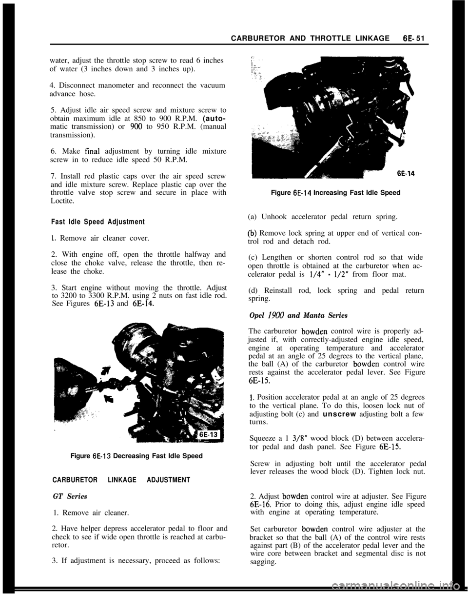
3. Start engine without moving the throttle. Adjust
to 3200 to 3300 R.P.M. using 2 nuts on fast idle rod.
See Figures 6E-13 and
6E-14.Figure
6E-13 Decreasing Fast Idle Speed
CARBURETOR LINKAGE ADJUSTMENT
GT Series1. Remove air cleaner.
2. Have helper depress accelerator pedal to floor and
check to see if wide open throttle is reached at carbu-
retor.
3. If adjustment is necessary, proceed as follows:
6E-14Figure
6E-14 Increasing Fast Idle Speed
(a) Unhook accelerator pedal return spring.
(b) Remove lock spring at upper end of vertical con-
trol rod and detach rod.
(c) Lengthen or shorten control rod so that wide
open throttle is obtained at the carburetor when ac-
celerator pedal is
l/4” - l/2” from floor mat.
(d) Reinstall rod, lock spring and pedal return
spring.
Opel 19W and Manta SeriesThe carburetor bowden control wire is properly ad-
justed if, with correctly-adjusted engine idle speed,
engine at operating temperature and accelerator
pedal at an angle of 25 degrees to the vertical plane,
the ball (A) of the carburetor bowden control wire
rests against the accelerator pedal lever. See Figure
6E-15.
1. Position accelerator pedal at an angle of 25 degrees
to the vertical plane. To do this, loosen lock nut of
adjusting bolt (c) and unscrew adjusting bolt a few
turns.
Squeeze a 1 3/S” wood block (D) between accelera-
tor pedal and dash panel. See Figure
6E-15.Screw in adjusting bolt until the accelerator pedal
lever releases the wood block (D). Tighten lock nut.
2. Adjust bowden control wire at adjuster. See Figure
6E-16. Prior to doing this, adjust engine idle speed
with engine at operating temperature.
Set carburetor bowden control wire adjuster at the
bracket so that the ball (A) of the control wire rests
against part (B) of the accelerator pedal lever and the
wire core between bracket and segmental disc is not
sagging.
Page 353 of 625
6F. 62 1973 OPEL SERVICE MANUAL
bleed into the vacuum line, allowing more manifold
vacuum to reach the vacuum motor. Whenever there
is nine inches or more of vacuum in the vacuum
motor, the diaphragm spring is compressed, the door
is opened.
When the engine is not running, the diaphragm
spring will always hold the door closed. However,
when the engine is running, the position of the door
depends on the air temperature in the air cleaner.
When starting a cold engine (air cleaner temperature
under 85 degrees), the air door will open immedi-
ately. This is because the air bleed valve in the sensor
is closed so that full manifold vacuum, is applied in
the vacuum motor. As soon as the air cleaner starts
receiving hot air from the heat stove, the sensor will
cause the air door to close partially, mixing cold air
with the hot air as necessary to regulate air cleaner
temperature within 20 degrees of the ideal 115 de-
grees air inlet temperature.
If underhood air temperature rises to 135 degrees,
the air bleed valve in the sensor will be wide open so
that vacuum to the vacuum motor approaches zero.
The diaphragm spring in the vacuum motor will hold
the air door closed tightly. If underhood temperature
rises above 135 degrees, carburetor inlet air tempera-
ture will also rise above 135 degrees.
While air cleaner temperature is being regulated, ac-
celerating the engine hard will cause the vacuum
level in the intake manifold and in the vacuum motor
to drop. Whenever vacuum drops below 5 inches, the
diaphragm spring will close the air
door in order to
get the
maxumum outside air flow required for max-
imum acceleration.
The carburetor is set by the manufacturer for
800-
850 RPM (automatic transmission) or 850-900 RPM
(manual transmission) and 1.5 to 2.5 percent CO.
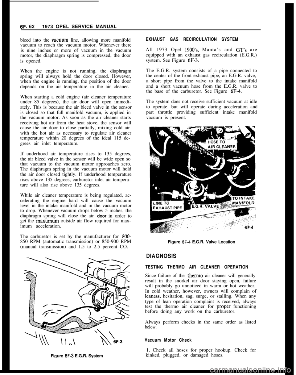
Figure 6F-3 E.G.R. System
EXHAUST GAS RECIRCULATION SYSTEM
All 1973 Opel 1900’s, Manta’s and GT’s are
equipped with an exhaust gas recirculation (E.G.R.)
system. See Figure
6F-3.
The E.G.R. system consists of a pipe connected to
the center of the front exhaust pipe, an E.G.R. valve,
a short pipe from the valve to the intake manifold
and a short vacuum hose from the E.G.R. valve to
the base of the carburetor. See Figure
6F-4.
The system does not receive sufficient vacuum at idle
to operate, but will operate during acceleration and
part throttle providing sufficient intake manifold
vacuum is present.
Figure 6F-4 E.G.R. Valve Location
DIAGNOSIS
TESTING THERMO AIR CLEANER OPERATION
Since failure of the therm0 air cleaner will generally
result in the snorkel air door staying open, failure
will probably go unnoticed in warm or hot weather.
In cold weather, however, owners will complain of
leaness, hesitation, sag, surge, or stalling. When any
type of lean operation complaint is received, always
test the thermo air cleaner for
proper functioning
before doing any work on the carburetor.
Always perform checks in the same order as listed
below.
Vacuum Motor Check
1. Check all hoses for proper hookup. Check for
kinked, plugged, or damaged hoses.
Page 360 of 625

GROUP 7
TRANSMISSION7A IClutch. . . . . . . . . . . . . . . . . . . . . . . . .7A- 1
7B IManualTransmission1 76-12 1
7c IAutomatic Transmission1 7C-36 1I
I
I
Page 362 of 625
CLUTCH7A. 1
CLUTCH
CONTENTS
Subject
DESCRIPTION AND OPERATION: Clutch andClutch
PedalMechanisms
. . . . . . . . . . . . . . . . . . . . . .
DIAGNOSIS:
Clutch
. . . . . . . . . . . . . . . . . . . . . . . . . . . . . . . . . . . . \
. . . . . . . . . . . . . . . . . . . . . . . . . . . . . . . . . . . . \
. . . . . . .
MAINTENANCE AND ADJUSTMENTS: Clutch LashAdjustment (GTOnly)
. . . . . . . . . . . . . . . . . . . . . . . . . . . . . .
Clutch Adjustment (All 1.9 Engines Except GT). . . .
Control CableAdjustment. . . . . . . . . . . . . . . . . . . . . . . . . . . . . . . . . . . . \
. . . . . . . . . .
MAJOR REPAIR:
Clutch Removal and Installation
. . . . . . . . . . . . . . . . . . . . . . . . . . . . . . . . .
Clutch Control Cable. . . . . . . . . . . . . . . . . . . . . . . . . . . . . . . . . . . . \
. . . . . . . . . . . . . . . . . . . .
SPECIFICATIONS:
Specifications
. . . . . . . . . . . . . . . . . . . . . . . . . . . . . . . . . . . . . . . . \
. . . . . . . . . . . . . . . . . . . . . . . . . . . . .
Page No.
7A-
1
7A-2
7A-4
7A-4
7A-4
IA-5
7A- 7
7A-7
DESCRIPTION AND OPERATION
CLUTCH PEDAL MECHANISM GT Only
The pedal lever pivots on a tubular steel shaft and
operates the clutch release yoke thru a sheathed ca-
ble attached directly to the upper end of the pedallever. Pedal return is accomplished thru the cable by
the clutch yoke return spring at the transmission.
The pedal return stop
is a nonadjustable rubber
bumper inserted through the upper end of the pedal leverjust below the cable attaching point. The clutch
cable is sheathed in woven steel and weather pro-
tected by a plastic and fabric covering. An eyelet is
wedged on the upper end and fits over a formed
hook on the upper end of the pedal. The lower end
is provided with a
wedged ball stud arrangement
that slips into a slot in the clutch release lever. See
Figure
7A-6.
Opel 1900 and Manta
The pedal lever pivots on a tubular steel shaft and
operates the clutch release yoke through a sheathed
cable attached directly to the upper end of the pedal
lever. Pedal return is accomplished through a spring
attached to the pedal below the pivot shaft and to the
pedal assembly mounting bracket at the bulkhead. Clutch actuation works without pedal-free travel and
a warning device is provided which actuates an in-
dicator lamp in the instrument panel indicating
necessity of clutch adjustment. The clutch cable is
sheathed in
woven steel and weather protected by a
plastic fabric covering. An eyelet is wedged on the
upper end and fits over a formed hook on the upper
end of the pedal. The lower end is provided with a
wedged ball stud arrangement that slips into a slot in the clutch release lever. See Figure
7A-7.
Clutch Mechanism
The clutch assembly is enclosed in the bell housing.
The clutch release bearing and release fork are of
conventional design, with the fork pivoting on a ball
stud located opposite the control cable attaching
point. The bearing flange tits over two vertical pins
which are riveted to and extend into the eye of the
yoke.
The clutch pressure plate is similar in design to the
Buick Century pressure plate. A radially slotted dia-
phragm pivoting on two steel wire rings is retained
to the clutch cover by eight rivets. The clutch driven
member is a
6-3/4 inches diameter single plate dry
disc with torsional damper springs and spring leaves
between facings to cushion application. Dampener
springs in clutch disc assembly are
preloaded.
Page 363 of 625
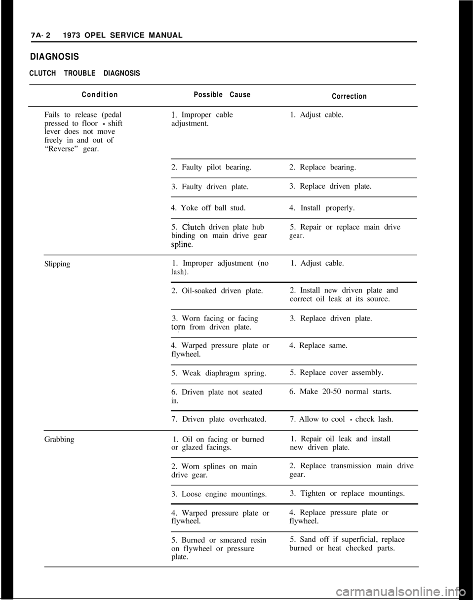
7A- 21973 OPEL SERVICE MANUALDIAGNOSIS
CLUTCH TROUBLE DIAGNOSIS
ConditionPossible Cause
CorrectionFails to release (pedal
1. Improper cable1. Adjust cable.
pressed to floor
- shiftadjustment.
lever does not move
freely in and out of
“Reverse” gear.
2. Faulty pilot bearing.2. Replace bearing.
3. Faulty driven plate.3. Replace driven plate.
4. Yoke off ball stud.4. Install properly.
5. Clutch driven plate hub5. Repair or replace main drive
binding on main drive gear
gear.spline.
Slipping1. Improper adjustment (no1. Adjust cable.
lash).2. Oil-soaked driven plate.2. Install new driven plate and
correct oil leak at its source.
3. Worn facing or facing3. Replace driven plate.tofn from driven plate.
4. Warped pressure plate or4. Replace same.
flywheel.
5. Weak diaphragm spring.5. Replace cover assembly.
6. Driven plate not seated6. Make 20-50 normal starts.
in.7. Driven plate overheated.7. Allow to cool
- check lash.
Grabbing1. Oil on facing or burned1. Repair oil leak and install
or glazed facings.new driven plate.
2. Worn splines on main2. Replace transmission main drive
drive gear.gear.
3. Loose engine mountings.3. Tighten or replace mountings.
4. Warped pressure plate or4. Replace pressure plate or
flywheel.flywheel.
5. Burned or smeared resin5. Sand off if superficial, replace
on flywheel or pressureburned or heat checked parts.
plate.
Page 364 of 625
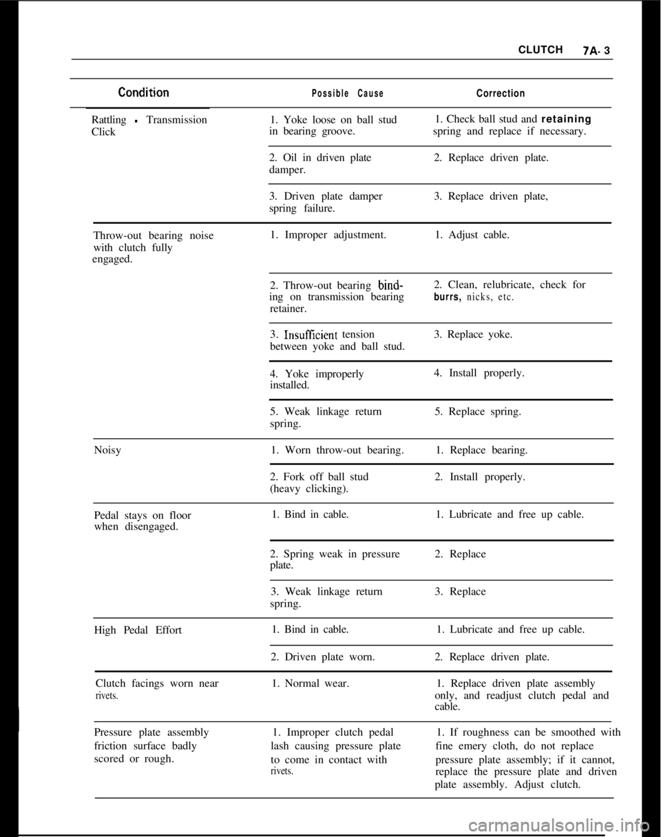
CLUTCH7A- 3Possible CauseCorrectionRattling
- Transmission
Click1. Yoke loose on ball stud
in bearing groove.1. Check ball stud and retaining
spring and replace if necessary.
2. Oil in driven plate
damper.2. Replace driven plate.
3. Driven plate damper
spring failure.3. Replace driven plate,
Throw-out bearing noise
with clutch fully
engaged.1. Improper adjustment.1. Adjust cable.
2. Throw-out bearing bind-
ing on transmission bearing
retainer.2. Clean, relubricate, check for
burrs, nicks, etc.3.
InsuffIcient tension
between yoke and ball stud.3. Replace yoke.
4. Yoke improperly
installed.4. Install properly.
5. Weak linkage return
spring.5. Replace spring.
Noisy1. Worn throw-out bearing.1. Replace bearing.
2. Fork off ball stud
(heavy clicking).2. Install properly.
Pedal stays on floor
when disengaged.1. Bind in cable.1. Lubricate and free up cable.
2. Spring weak in pressure
plate.2. Replace
3. Weak linkage return
spring.3. Replace
High Pedal Effort1. Bind in cable.
2. Driven plate worn.1. Lubricate and free up cable.
2. Replace driven plate.
Clutch facings worn near
rivets.1. Normal wear.1. Replace driven plate assembly
only, and readjust clutch pedal and
cable.
Pressure plate assembly
friction surface badly
scored or rough.1. Improper clutch pedal
lash causing pressure plate
to come in contact with
rivets.1. If roughness can be smoothed with
fine emery cloth, do not replace
pressure plate assembly; if it cannot,
replace the pressure plate and driven
plate assembly. Adjust clutch.
Page 365 of 625
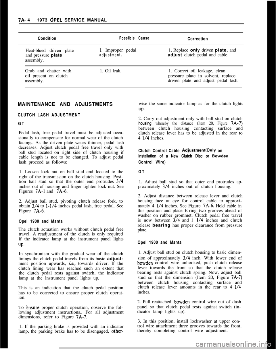
7A- 41973 dPEL SERVICE MANUALConditionPossible CauseCorrectionHeat-blued driven plate
and pressure plate
assembly.
1. Improper pedal1. Replace only driven plate, and
adjustment.adjust clutch pedal and cable.
Grab and chatter with
oil present on clutch
assembly.1. Oil leak.1. Correct oil leakage, clean
pressure plate in solvent, replace
driven plate and adjust pedal lash.
MAINTENANCE AND ADJUSTMENTS
CLUTCH LASH ADJUSTMENT
GTPedal lash, free pedal travel must be adjusted occa-
sionally to compensate for normal wear of the clutch
facings. As the driven plate wears thinner, pedal lash
decreases. Adjust clutch pedal free travel only with
ball stud located on right side of clutch housing if
cable length is not to be changed. To adjust pedal
lash proceed as follows:
1. Loosen lock nut on ball stud end located to the
right of the transmission on the clutch housing. Posi-
tion ball stud so that the outer end protrudes 3/4
inches out of housing and finger tighten lock nut. See
Figures
7A-1 and 7A-6.
2. Adjust ball stud, pivoting clutch release fork, to
obtain 3/4 to
l-1/4 inches pedal lash, free pedal. See
Figure 7A-6.
Opel 1900 and MantaThe clutch actuation works without clutch pedal free
travel. A readjustment of the clutch is only required
if the indicator lamp at the instrument panel lights
up.In synchronism with the gradual wear of the clutch
linings the clutch pedal travels from its basic adjust-
ment position upwards,
ie., towards driver. If the
clutch lining wear has reached such an extent that
the clutch pedal rests against switch, the indicator
lamp at the instrument panel lights up.
This is an indication that the clutch pedal position
has to be corrected to ensure proper clutch operat-
ion.
To
&~sure proper clutch operation, observe the fol-
lowing adjustment instructions.. For all adjustment
dimensions, refer to Figure 7A-7.
1. If the parking brake is provided with an indicator
lamp, the parking brake has to be disengaged, other-wise the same indicator lamp as for the clutch lights
UP.2. Carry out adjustment only with ball stud on clutch
housing whereby the distance (Item 20, Figure 7A-7)
between clutch housing contacting surface and
clutch release lever has to be adjusted in the rear to
4
l/4 inches.
Clutch Control Cable Adjustment(Only on
Installation of a New Clutch Disc or
Bowden
Control Wire)
GT1. Adjust ball stud so that outer end protrudes ap-
proximately 3/4 inches out of clutch housing.
2. Adjust distance between release lever and clutch
housing face at eye for control cable to approxi-
mately 4
l/4 inches. See Figure 7A-6. Hold cable in
this position and place E-ring two grooves ahead of
washer on rubber grommet. Clutch pedal free travel
is now between 3/4 and 1
l/4 inches and clutch
release bearing has proper clearance from pressure
plate.
Opel 1900 and Manta1. Adjust ball stud on clutch housing to basic dimen-
sion of approximately 3/4 inch. With lower end ofbowden control wire unhooked, push clutch release
lever towards the front so that the clutch release
bearing rests against clutch spring. Now, adjust ball
stud so that the dimension (Item 20, Figure
7A-7)between clutch housing contacting surface and
clutch release lever amounts in the rear to 4
l/4
inches.2. Pull reattached bowden control wire out of dash
panel so that clutch pedal rests against switch (in-
dicator lamp lights up).
3. In this position, install lockwasher at upper con-
trol wire attachment three grooves towards the front,
thereby completing control wire adjustment.
Page 366 of 625
CLUTCH?A- 5MAJOR REPAIR
CLUTCH REMOVAL AND INSTALLATION
Remove Clutch1. Remove transmission. Refer to Manual Transmis-
sion for removal procedure.
2. Remove bolts from engine support brackets, both
sides. Let brackets hang by front bolts.
3. Remove flywheel cover pan.
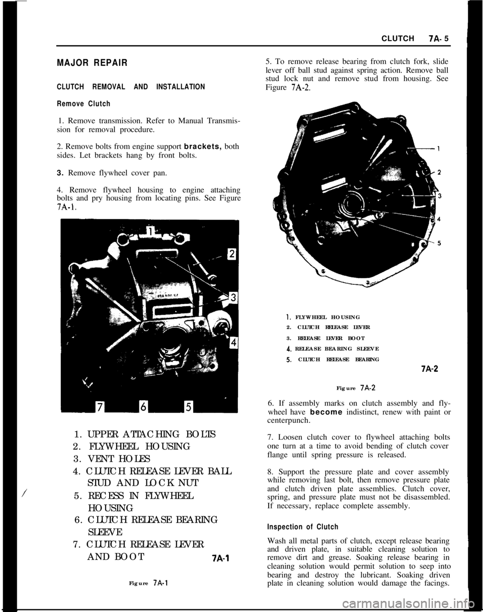
4. Remove flywheel housing to engine attaching
bolts and pry housing from locating pins. See Figure7A-1.
/1. UPPER ATTACHING BOLTS
2. FLYWHEEL HOUSING
3. VENT HOLES
4. CLUTCH RELEASE LEVER BALL
STUD AND LOCK NUT
5. RECESS IN FLYWHEEL
HOUSING
6. CLUTCH RELEASE BEARING
SLEEVE
7. CLUTCH RELEASE LEVER
AND BOOT
7A-1Figure 7A-15. To remove release bearing from clutch fork, slide
lever off ball stud against spring action. Remove ball
stud lock nut and remove stud from housing. See
Figure
7A-2.
1. FLYWHEEL HOUSING
2. CLUTCH RELEASE LEVER
3. RELEASE LEVER BOOT
4. RELEASE BEARING SLEEVES. CLUTCH RELEASE BEARINGi-A-2
Figure 7A-2
6. If assembly marks on clutch assembly and fly-
wheel have become indistinct, renew with paint or
centerpunch.
7. Loosen clutch cover to flywheel attaching bolts
one turn at a time to avoid bending of clutch cover
flange until spring pressure is released.
8. Support the pressure plate and cover assembly
while removing last bolt, then remove pressure plate
and clutch driven plate assemblies. Clutch cover,
spring, and pressure plate must not be disassembled.
If necessary, replace complete assembly.
Inspection of ClutchWash all metal parts of clutch, except release bearing
and driven plate, in suitable cleaning solution to
remove dirt and grease. Soaking release bearing in
cleaning solution would permit solution to seep into
bearing and destroy the lubricant. Soaking driven
plate in cleaning solution would damage the facings.
Page 367 of 625
7A- 61973 OPEL SERVICE MANUAL1. FIywheeI and Pressure PlateExamine friction surfaces of flywheel and pressure
plate for scoring or roughness. Slight roughness may
be smoothed with fine emery cloth, but if surface is
deeply scored or grooved the part should be re-
placed.
2.
CJutch Driven Plate
Inspect driven plate for condition of facings, loose
rivets, broken or very loose torsional springs.
If facings are worn down near rivets or are oily, the
plate assembly should be replaced. A very slight
amount of oil on clutch facings will cause clutch grab
and chatter. A large amount of oil on facings will
cause slippage. Removal of oil by solvents or by buff-
ing is not practical since oil will continue to bleed
from facing material when hot.
When oil is found on driven plate facings, examine
transmission drainback hole, pilot bushing, engine
rear main bearing and other points of possible oil
leakage.
Test the fit of driven plate hub on transmission main
drive gear for an easy sliding fit.
Regardless of whether the old plate or a new one is
to be installed, the plate should be checked for run-
out. Lateral run-out measured at disc circumference
should not exceed
.016 inch.
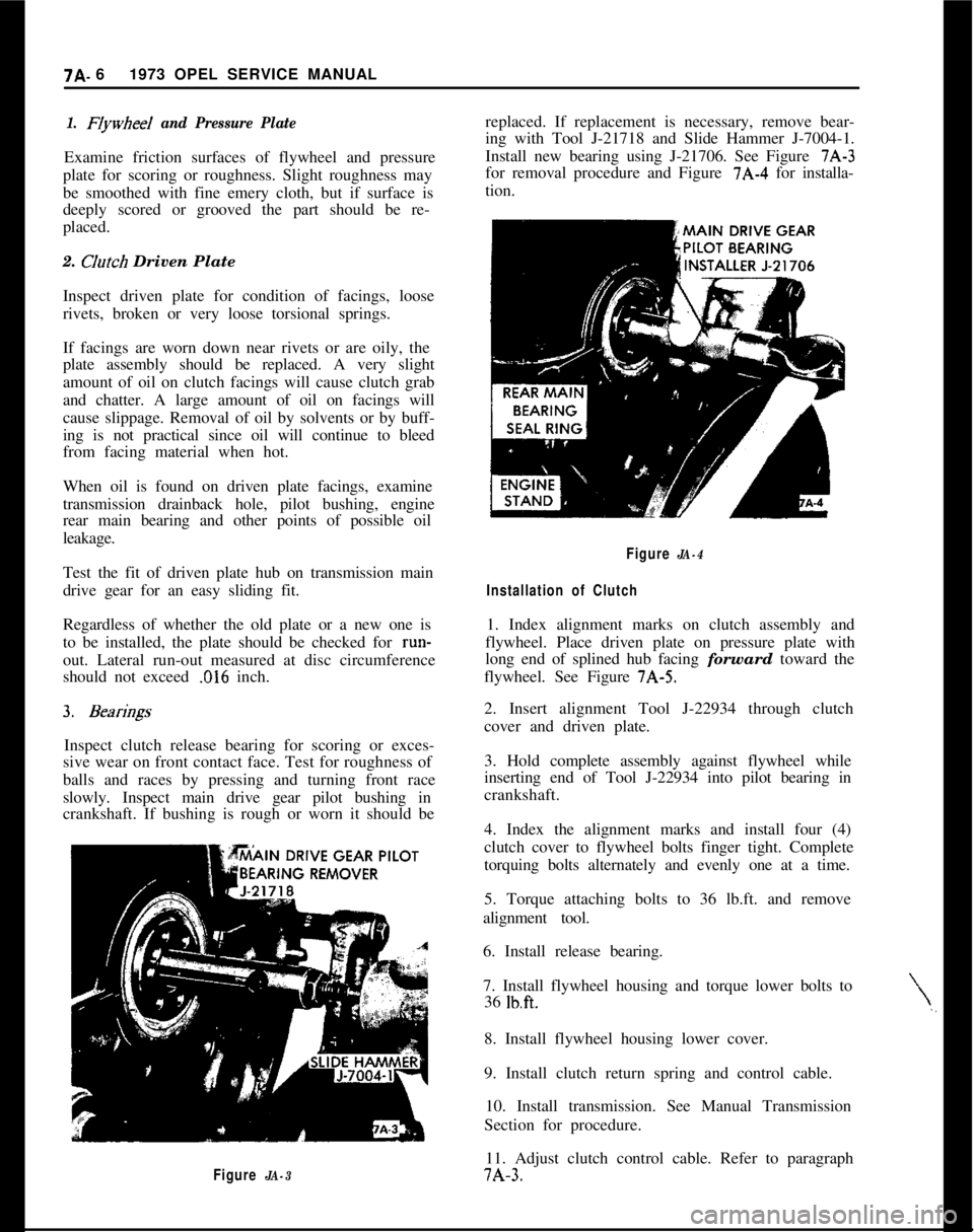
Inspect clutch release bearing for scoring or exces-
sive wear on front contact face. Test for roughness of
balls and races by pressing and turning front race
slowly. Inspect main drive gear pilot bushing in
crankshaft. If bushing is rough or worn it should be
Figure JA-3replaced. If replacement is necessary, remove bear-
ing with Tool J-21718 and Slide Hammer J-7004-1.
Install new bearing using J-21706. See Figure 7A-3
for removal procedure and Figure 7A-4 for installa-
tion.
\,,
Figure JA-4
Installation of Clutch1. Index alignment marks on clutch assembly and
flywheel. Place driven plate on pressure plate with
long end of splined hub facing forward toward the
flywheel. See Figure 7A-5.
2. Insert alignment Tool J-22934 through clutch
cover and driven plate.
3. Hold complete assembly against flywheel while
inserting end of Tool J-22934 into pilot bearing in
crankshaft.
4. Index the alignment marks and install four (4)
clutch cover to flywheel bolts finger tight. Complete
torquing bolts alternately and evenly one at a time.
5. Torque attaching bolts to 36 lb.ft. and remove
alignment tool.
6. Install release bearing.
7. Install flywheel housing and torque lower bolts to
36
lb.ft.8. Install flywheel housing lower cover.
9. Install clutch return spring and control cable.
10. Install transmission. See Manual Transmission
Section for procedure.
11. Adjust clutch control cable. Refer to paragraph7A-3.