tow OPEL GT-R 1973 Owner's Guide
[x] Cancel search | Manufacturer: OPEL, Model Year: 1973, Model line: GT-R, Model: OPEL GT-R 1973Pages: 625, PDF Size: 17.22 MB
Page 280 of 625
DISC BRAKES5B- 21caliper half collars and the clamp rings are correctly
positioned on rubber seals.
12. Install brake caliper on steering knuckle, torqu-
ing bolts to 72 lb.ft.or with an equivalent part, if replacement becomes
necessary. Do not use a replacement part of lesser
quality or substitute design. Torque values must be
used as specified during reassembly to assure proper
retention of this part.
CAUTION: This disc brake caliper attachments fas-
tener is an important attaching part in that it couldatExt the performance of vital components and sys-
tems, and/or could result in
ma@r repair expense. It
must be replaced with one of the
same part number13. Attach brake pipe to caliper and torque to 22
lb.ft.14. Bleed brakes as necessary.
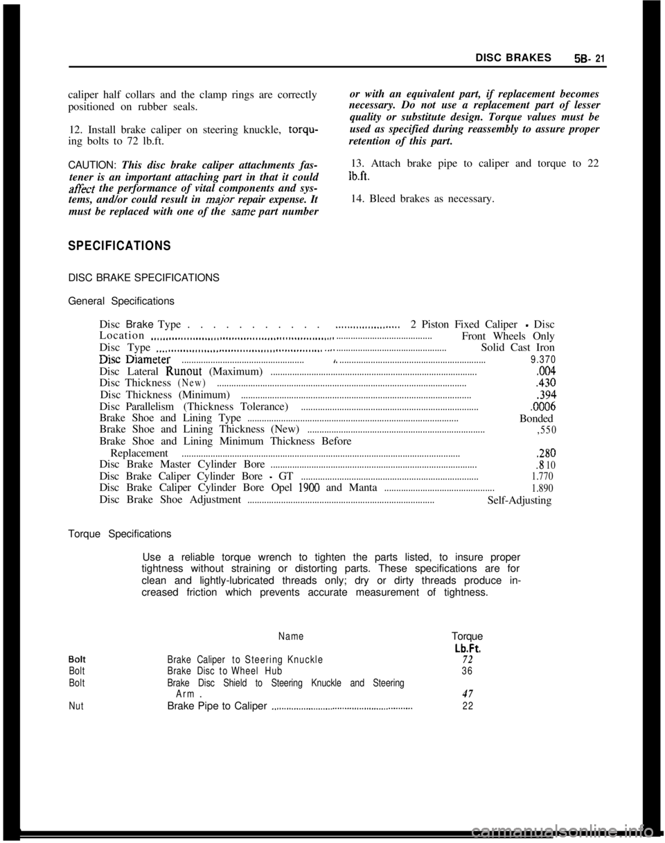
SPECIFICATIONSDISC BRAKE SPECIFICATIONS
General Specifications
DiscBrakeType. . . . . . . . . . .
Location
..,,.,..__....__.,,.,,,................,,,................,....Disc Type
.._.......................................................I.-. -.
......................2 Piston Fixed Caliper - Disc
........................................Front Wheels Only
..............................................Solid Cast Iron
useuameter...................................................,..............................................................9.370Disc Lateral Runout (Maximum)
......................................................................................,004DiscThickness
(New).........................................................................................................430DiscThickness(Minimum)
................................................................................................,394DiscParallelism(ThicknessTolerance)
...........................................................................0006Brake Shoe and Lining Type
........................................................................................Bonded
Brake Shoe and Lining Thickness (New)
..........................................................................
,550Brake Shoe and Lining Minimum Thickness Before
Replacement
....................................................................................................................,280Disc Brake Master Cylinder Bore
.......................................................................................8 10Disc Brake Caliper Cylinder Bore
- GT..........................................................................1.770Disc Brake Caliper Cylinder Bore Opel
1900 and Manta..............................................
1.890Disc Brake Shoe Adjustment
..............................................................................Self-Adjusting
Torque Specifications
Use a reliable torque wrench to tighten the parts listed, to insure proper
tightness without straining or distorting parts. These specifications are for
clean and lightly-lubricated threads only; dry or dirty threads produce in-
creased friction which prevents accurate measurement of tightness.
Bolt
Bolt
Bolt
NutName
BrakeCalipertoSteeringKnuckle
BrakeDisctoWheelHub
Brake Disc Shield to Steering Knuckle and Steering
Arm.
Brake Pipe to Caliper
.,.,...............................,......................Torque
Lb.Ft.
72
36
47
22
Page 299 of 625
6A- 8 1973 OPEL SERVICE MANUAL
Actual adjustment is made by backing off adjusting
nut at the rocker arm until clearance exists between the valve stem, rocker arm, and lifter. Then slowly
tighten adjusting nut until clearance is eliminated.
When clearance is eliminated, turn adjusting nut one
full turn (clockwise). This positions the hydraulic
piston of the hydraulic lifter mid-point in its total
available travel, and no further adjustment is re-
quired.
MAJOR REPAIR
ENGINE ASSEMBLY REMOVAL AND
INSTALLATION
Removal (Opel 1900 and Manta)’
The engine assembly on the Opel 1900 and Manta
can be removed together with the transmission
through the top of the engine compartment.
1. Remove hood (scribe hood hinge to hood mount-
ing location).
2. Disconnect battery negative cable.
3. Drain coolant at lower radiator hose.
4. Remove upper and lower radiator hoses.
5. Remove radiator and fan
shrbud.
6. Disconnect heater hoses.
7. Disconnect brake booster
vacuum hose.
8. Remove air cleaner.
9. Disconnect electrical connections and accelerator
linkage. 10. Remove console.
11. Remove shift lever boot, plate, and shift lever.
12. Raise car on hoist.
13. Disconnect fuel line at pump.
14. Remove front stone shield.
15. Disconnect speedo-cable, back-up light switch,
and clutch cable.
16. Remove drive shaft. I
17. Disconnect exhaust pipe
ar$l bell housing sup-
port.
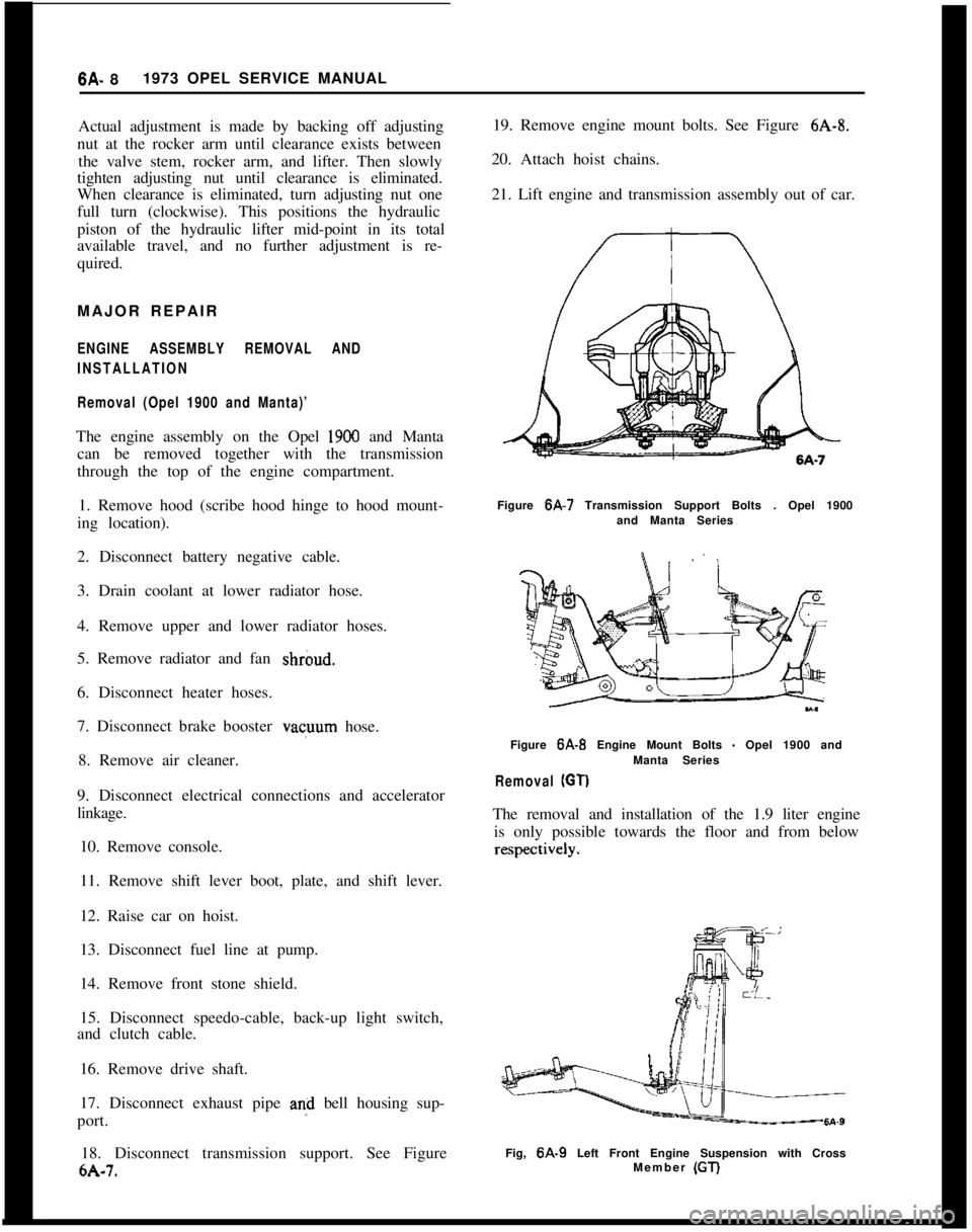
18. Disconnect transmission support. See Figure
6A-7. 19. Remove engine mount bolts. See Figure
6A-8.
20. Attach hoist chains.
21. Lift engine and transmission assembly out of car.
Figure 6A-7 Transmission Support Bolts . Opel 1900
and Manta Series
Figure
6A-B Engine Mount Bolts - Opel 1900 and
Manta Series
Removal (GT)
The removal and installation of the 1.9 liter engine is only possible towards the floor and from below
Fig, 6A-9 Left Front Engine Suspension with Cross
Member (GT)
Page 306 of 625
ENGINE MECHANICAL AND MOUNTS6A- 15New inlet valves must not be refaced or lapped with
grinding compound.The correct angle for the intake
and exhaust valve head is 44 degrees.10. Install cylinder head.
11. Adjust valve clearance. See MAINTENANCE
AND ADJUSTMENTS.
7. Inspect valve guides. Worn or pitted guides can be
reamed to accept valves with oversize stems. Over-
size valves are occasionally used in production.
Oversize valves are marked
’ 1 u “2” or “A” and are
stamped into the valve stem end and also stamped
near spark plug hole. See Figure 6A-22.
Replacing Rocker Arm Studs1. When replacing rocker arm studs become
neces-
sary, remove air cleaner, rocker arm cover and
rocker arm.
8. Reseat valve seats in cylinder head in the following
sequence:
Intake
NOTE:The rocker arm studs are screwed into the
cylinder head. A tapered part of the stem serves to
a void stud loosening.With 45 degrees cutter, remove burnt structure until
a metallic bright seat is obtained. Lightly coat valve
head with red lead, insert it into guide and turn it
under light pressure several times back and forth.
Thereby a contact pattern is obtained and the seat
width can be measured. If valve does not seat per-
fectly all around, lightly recut valve seat to the estab-
lished seat width of
,049” - .059” with 30 degrees
correction cutter.
ExhaustThe directions for reconditioning intake valve seats
apply in principle also to exhaust valve seat recondi-
tioning with the exception that the valve seat width
should be
.063-,073 in. and different cutters are em-
ployed.
NOTE:
: OTse new valve seals whenever
valves are reconditioned.9. Lube valves with engine oil and reinstall valves,
valve springs, caps and cap retainers using J-8062.
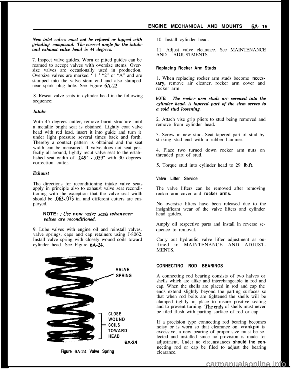
Install valve spring with closely wound coils toward
cylinder head. See Figure
6A-24.2. Attach vise grip pliers to stud being removed and
remove from cylinder head.
3. Screw in new stud. Seat tapered part of stud by
striking stud end with a rubber hammer.
4. Place two turned down rocker arm nuts on
threaded part of stud.
5. Torque stud into cylinder head to 29
lb.ft.
Valve Lifter ServiceThe valve lifters can be removed after removing
rocker arm cover and rocker arms.No oversize lifters have been released due to the
insignificant wear of the valve lifters and cylinder
head guides.
Amply oil respective parts and install in reverse se-
quence to removal.
Carry out hydraulic valve lifter adjustment as ou-
tlined in MAINTENANCE AND ADJUST-
MENTS.
VALVE
I SPRING
CLOSE
WOUND
COILS
TOWARD
HEAD6A-24
Figure 6A-24 Valve SpringCONNECTING ROD BEARINGSA connecting rod bearing consists of two halves or
shells which are alike and interchangeable in rod and
cap. When the shells are placed in rod and cap the
ends extend slightly beyond the parting surfaces so
that when rod bolts are tightened the shells will be
clamped tightly in place to insure positive seating
and to prevent turning. Theends of shells must never
be tiled flush with parting surface of rod or cap.
If a precision type connecting rod bearing becomes
noisy or is worn so that clearance on crankpin is
excessive, a new bearing of proper size must be se-
lected and installed since no provision is made for
adjustment. Under no circumstances should the con-necting rod or cap be filed to adjust the bearing
clearance.
Page 312 of 625
ENGINE MECHANICAL AND MOUNTS6A- 21
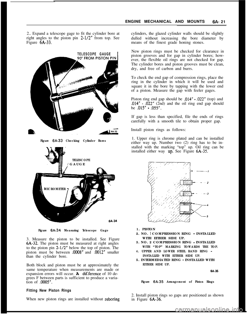
2.. Expand a telescope gage to fit the cylinder bore at
right angles to the piston pin 2-l/2” from top. See
Figure 6A-33.cylinders, the glazed cylinder walls should be slightly
dulled without increasing the bore diameter by
means of the finest grade honing stones.
TELESCOPE GAUGE1
Figure 6A-33 Checking Cylinder Bores
TELESCOPE/GAUGE
MICROMETER
Figure
6A-34 Measuring Telescope Gage3. Measure the piston to be installed. See Figure6A-32. The piston must be measured at right angles
to the piston pin
2-l/2” below the top of piston. The
piston must be between
.C008” and .0012” smaller
than the cylinder bore.
Both block and piston must be at approximately the
same temperature when measurements are made or
expansion errors will occur. A
dif.ference of 10 de-
grees F between parts is sufficient to produce a varia-
tion of .0005”.
Fitting New Piston RingsWhen new piston rings are installed without reboringNew piston rings must be checked for clearance in
piston grooves and for gap in cylinder bores; how-
ever, the flexible oil rings are not checked for gap.
The cylinder bores and piston grooves must be clean,
dry, and free of carbon and burrs.
To check the end gap of compression rings, place the
ring in the cylinder in which it will be used and
square it in the bore by tapping with the lower end
of a piston. Measure the gap with feeler gages.
Piston ring end gap should be
,014” - ,022” (top) and
,014” - ,022” (2nd) and the oil ring end gap should
be
.015” - ,055”.
If gap is less than specified, file the ends of rings
carefully with a smooth tile to obtain proper gap.
Install piston rings as follows:
1. Upper ring is chrome plated and can be installed
either way up. Number two (2) ring has to be in-
stalled with the marking “top” up. Oil ring can be
installed either way
up. See Figure 6A-35.
1. PISTON
2. NO.
I COMPRESSION RING - INSTALLED
WITH EITHER SIDE UP.
3. NO. 2 COMPRESSION RING - INSTALLED
WITH “TOP” MARKING TOWARDS THE TOP.
4. UPPER AND LOWER STEEL BAND RING
-
INSTALLED WITH EITHER SIDE UP.5. INTERMEDIATED RING
- INSTALLED WITH
EITHER SIDE UP.
6A-35
Figure 6A.35 Arrangement of Piston Rings2. Install piston rings so gaps are positioned as shown
in Figure 6A-36.
Page 313 of 625
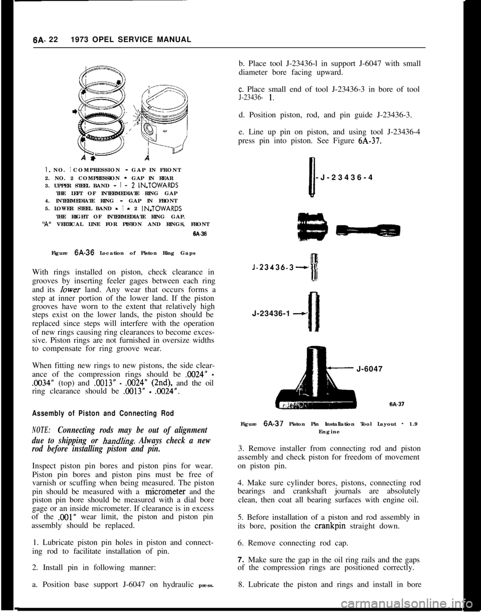
6A- 221973 OPEL SERVICE MANUALI. NO. I COMPRESSION - GAP IN FRONT
2. NO. 2 COMPRESSION - GAP IN REAR
3. UPPER STEEL BAND -
I - 2 IN.TOWARDS
THE LEFT OF INTERMEDIATE RING GAP
4. INTERMEDIATE RING - GAP IN FRONT
5. LOWER STEEL BAND -
I - 2 IN.TOWARDS
THE RIGHT OF INTERMEDIATE RING GAP.‘A” VERTICAL LINE FOR PISTON AND RINGS, FRONT
6A-36Figure 6A-36 Location of Piston Ring Gaps
With rings installed on piston, check clearance in
grooves by inserting feeler gages between each ring
and its Iower land. Any wear that occurs forms a
step at inner portion of the lower land. If the piston
grooves have worn to the extent that relatively high
steps exist on the lower lands, the piston should be
replaced since steps will interfere with the operation
of new rings causing ring clearances to become exces-
sive. Piston rings are not furnished in oversize widths
to compensate for ring groove wear.
When fitting new rings to new pistons, the side clear-
ance of the compression rings should be X024”
-
.1X34” (top) and .0013” - .OO24” (2nd), and the oil
ring clearance should be
.OO13” - .0024”.
Assembly of Piston and Connecting Rod
NOTE:Connecting rods may be out of alignment
due to shipping or
hand/i& Always check a new
rod before installing piston and pin.Inspect piston pin bores and piston pins for wear.
Piston pin bores and piston pins must be free of
varnish or scuffing when being measured. The piston
pin should be measured with a niicrometer and the
piston pin bore should be measured with a dial bore
gage or an inside micrometer. If clearance is in excess
of the
,001” wear limit, the piston and piston pin
assembly should be replaced.
1. Lubricate piston pin holes in piston and connect-
ing rod to facilitate installation of pin.
2. Install pin in following manner:
a. Position base support J-6047 on hydraulic press.b. Place tool J-23436-l in support J-6047 with small
diameter bore facing upward.
c. Place small end of tool J-23436-3 in bore of tool
J-23436- 1.d. Position piston, rod, and pin guide J-23436-3.
e. Line up pin on piston, and using tool J-23436-4
press pin into piston. See Figure 6A-37.
Ii-J-23436-4
J-23436-3--,J-23436-1
--cJ-6047
Figure 6A-37 Piston Pin Installation Tool Layout
- 1.9
Engine
3. Remove installer from connecting rod and piston
assembly and check piston for freedom of movement
on piston pin.
4. Make sure cylinder bores, pistons, connecting rod
bearings and crankshaft journals are absolutely
clean, then coat all bearing surfaces with engine oil.
5. Before installation of a piston and rod assembly in
its bore, position the crankpin straight down.
6. Remove connecting rod cap.
7. Make sure the gap in the oil ring rails and the gaps
of the compression rings are positioned correctly.
8. Lubricate the piston and rings and install in bore
Page 314 of 625
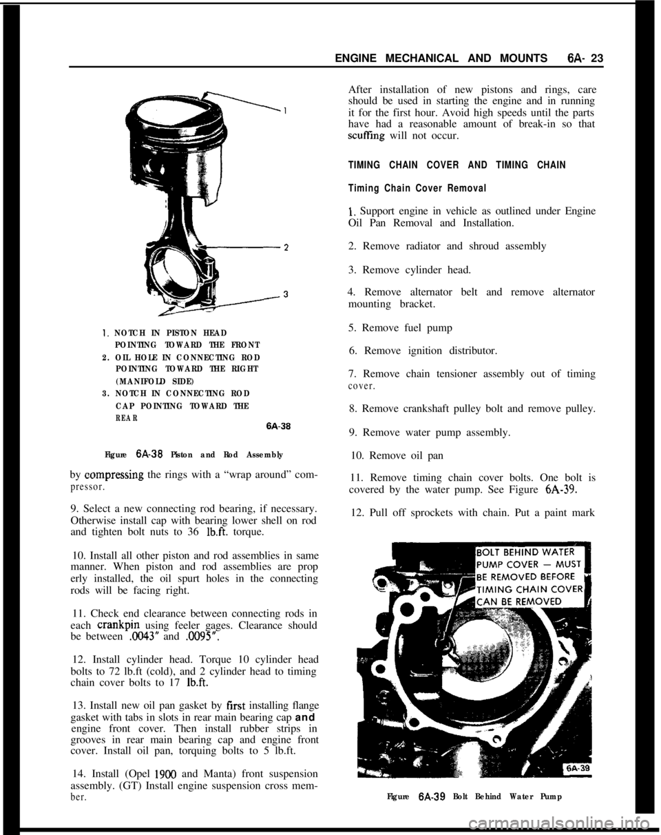
ENGINE MECHANICAL AND MOUNTS6A- 231. NOTCH IN PISTON HEAD
POINTING TOWARD THE FRONT
2. OIL HOLE IN CONNECTING ROD
POINTING TOWARD THE RIGHT
(MANIFOLD SIDE)
3. NOTCH IN CONNECTING ROD
CAP POINTING TOWARD THE
REAR6A-36
Figure
6A-39 Piston and Rod Assemblyby oompressing the rings with a “wrap around” com-
pressor.9. Select a new connecting rod bearing, if necessary.
Otherwise install cap with bearing lower shell on rod
and tighten bolt nuts to 36
lb.ft. torque.
10. Install all other piston and rod assemblies in same
manner. When piston and rod assemblies are prop
erly installed, the oil spurt holes in the connecting
rods will be facing right.
11. Check end clearance between connecting rods in
each crankpin using feeler gages. Clearance should
be between
.0043” and .0095”.
12. Install cylinder head. Torque 10 cylinder head
bolts to 72 lb.ft (cold), and 2 cylinder head to timing
chain cover bolts to 17
lb.ft.13. Install new oil pan gasket by first installing flange
gasket with tabs in slots in rear main bearing cap and
engine front cover. Then install rubber strips in
grooves in rear main bearing cap and engine front
cover. Install oil pan, torquing bolts to 5 lb.ft.
14. Install (Opel
1900 and Manta) front suspension
assembly. (GT) Install engine suspension cross mem-
ber.After installation of new pistons and rings, care
should be used in starting the engine and in running
it for the first hour. Avoid high speeds until the parts
have had a reasonable amount of break-in so that
scuffling will not occur.
TIMING CHAIN COVER AND TIMING CHAIN
Timing Chain Cover Removal
1, Support engine in vehicle as outlined under Engine
Oil Pan Removal and Installation.
2. Remove radiator and shroud assembly
3. Remove cylinder head.
4. Remove alternator belt and remove alternator
mounting bracket.
5. Remove fuel pump
6. Remove ignition distributor.
7. Remove chain tensioner assembly out of timing
cover.8. Remove crankshaft pulley bolt and remove pulley.
9. Remove water pump assembly.
10. Remove oil pan
11. Remove timing chain cover bolts. One bolt is
covered by the water pump. See Figure 6A-39.
12. Pull off sprockets with chain. Put a paint mark
Figure 6A-39 Bolt Behind Water Pump
Page 317 of 625
6A- 261973 OPEL SERVICE MANUAL
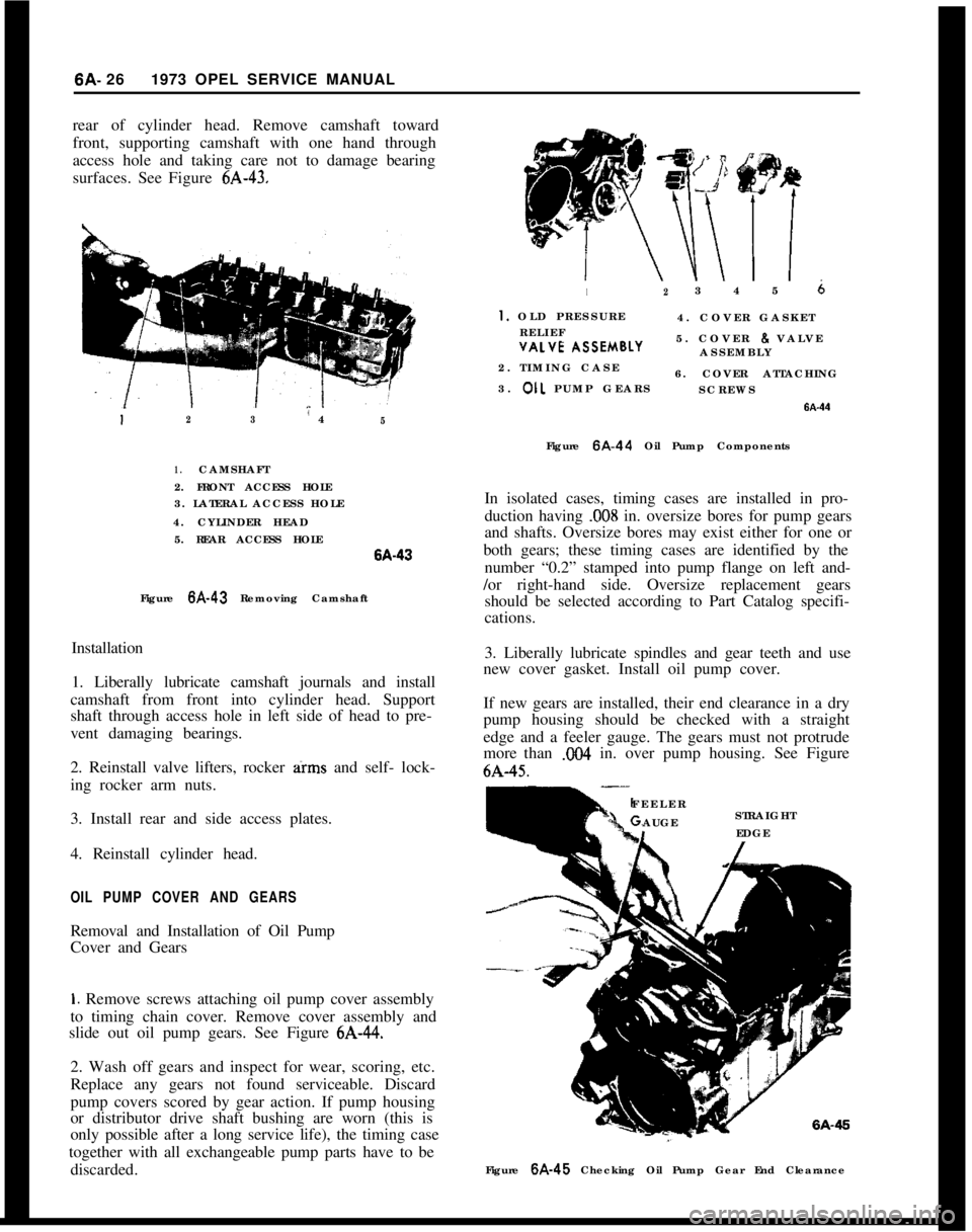
rear of cylinder head. Remove camshaft toward
front, supporting camshaft with one hand through
access hole and taking care not to damage bearing
surfaces. See Figure 6A-43.12345 6
I. OLD PRESSURE
4. COVER GASKET
RELIEF
~~- \SSEMBLY5. COVER 8 VALVE
ASSEMBLYVALVE I
2. TIMING CASE
6. COVER ATTACHING
3. OIL PUMP GEARS
SCREWS
123” 45Figure 6A-44 Oil Pump Components
1.CAMSHAFT
2. FRONT ACCESS HOLE
3. LATERAL ACCESS HOLE
4. CYLINDER HEAD
5. REAR ACCESS HOLEISA-43
Figure 6A-43 Removing Camshaft
Installation
1. Liberally lubricate camshaft journals and install
camshaft from front into cylinder head. Support
shaft through access hole in left side of head to pre-
vent damaging bearings.
2. Reinstall valve lifters, rocker arms and self- lock-
ing rocker arm nuts.
3. Install rear and side access plates.
4. Reinstall cylinder head.
OIL PUMP COVER AND GEARSRemoval and Installation of Oil Pump
Cover and Gears
1. Remove screws attaching oil pump cover assembly
to timing chain cover. Remove cover assembly and
slide out oil pump gears. See Figure 6A-44.
2. Wash off gears and inspect for wear, scoring, etc.
Replace any gears not found serviceable. Discard
pump covers scored by gear action. If pump housing
or distributor drive shaft bushing are worn (this is
only possible after a long service life), the timing case
together with all exchangeable pump parts have to be
discarded.In isolated cases, timing cases are installed in pro-
duction having
.008 in. oversize bores for pump gears
and shafts. Oversize bores may exist either for one or
both gears; these timing cases are identified by the
number “0.2” stamped into pump flange on left and-
/or right-hand side. Oversize replacement gears
should be selected according to Part Catalog specifi-
cations.
3. Liberally lubricate spindles and gear teeth and use
new cover gasket. Install oil pump cover.
If new gears are installed, their end clearance in a dry
pump housing should be checked with a straight
edge and a feeler gauge. The gears must not protrude
more than X04 in. over pump housing. See Figure6A-45.
FEELER
AUGESTRAIGHTIEDGE
Figure 6A-45 Checking Oil Pump Gear End Clearance
Page 365 of 625
7A- 41973 dPEL SERVICE MANUALConditionPossible CauseCorrectionHeat-blued driven plate
and pressure plate
assembly.
1. Improper pedal1. Replace only driven plate, and
adjustment.adjust clutch pedal and cable.
Grab and chatter with
oil present on clutch
assembly.1. Oil leak.1. Correct oil leakage, clean
pressure plate in solvent, replace
driven plate and adjust pedal lash.
MAINTENANCE AND ADJUSTMENTS
CLUTCH LASH ADJUSTMENT
GTPedal lash, free pedal travel must be adjusted occa-
sionally to compensate for normal wear of the clutch
facings. As the driven plate wears thinner, pedal lash
decreases. Adjust clutch pedal free travel only with
ball stud located on right side of clutch housing if
cable length is not to be changed. To adjust pedal
lash proceed as follows:
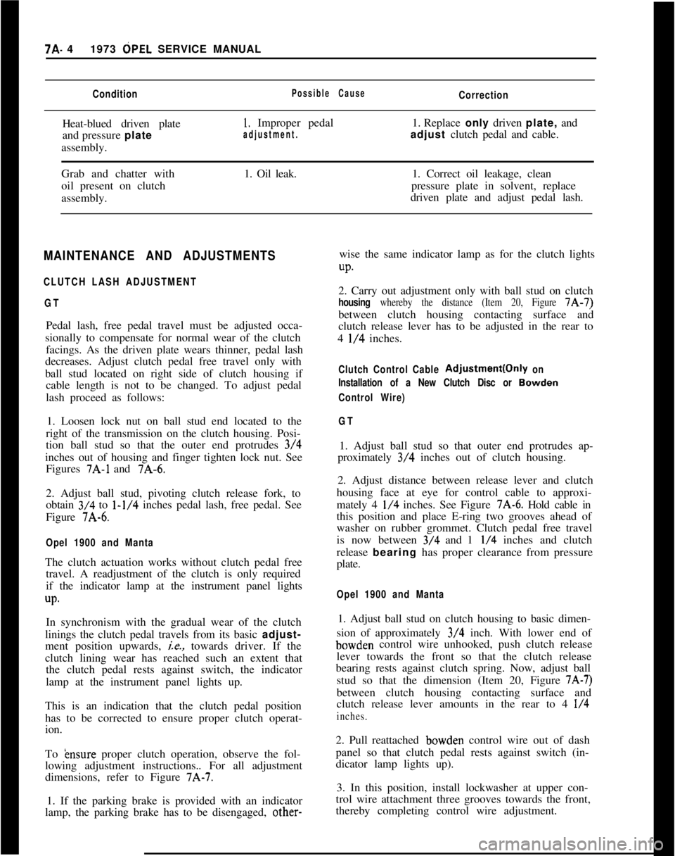
1. Loosen lock nut on ball stud end located to the
right of the transmission on the clutch housing. Posi-
tion ball stud so that the outer end protrudes 3/4
inches out of housing and finger tighten lock nut. See
Figures
7A-1 and 7A-6.
2. Adjust ball stud, pivoting clutch release fork, to
obtain 3/4 to
l-1/4 inches pedal lash, free pedal. See
Figure 7A-6.
Opel 1900 and MantaThe clutch actuation works without clutch pedal free
travel. A readjustment of the clutch is only required
if the indicator lamp at the instrument panel lights
up.In synchronism with the gradual wear of the clutch
linings the clutch pedal travels from its basic adjust-
ment position upwards,
ie., towards driver. If the
clutch lining wear has reached such an extent that
the clutch pedal rests against switch, the indicator
lamp at the instrument panel lights up.
This is an indication that the clutch pedal position
has to be corrected to ensure proper clutch operat-
ion.
To
&~sure proper clutch operation, observe the fol-
lowing adjustment instructions.. For all adjustment
dimensions, refer to Figure 7A-7.
1. If the parking brake is provided with an indicator
lamp, the parking brake has to be disengaged, other-wise the same indicator lamp as for the clutch lights
UP.2. Carry out adjustment only with ball stud on clutch
housing whereby the distance (Item 20, Figure 7A-7)
between clutch housing contacting surface and
clutch release lever has to be adjusted in the rear to
4
l/4 inches.
Clutch Control Cable Adjustment(Only on
Installation of a New Clutch Disc or
Bowden
Control Wire)
GT1. Adjust ball stud so that outer end protrudes ap-
proximately 3/4 inches out of clutch housing.
2. Adjust distance between release lever and clutch
housing face at eye for control cable to approxi-
mately 4
l/4 inches. See Figure 7A-6. Hold cable in
this position and place E-ring two grooves ahead of
washer on rubber grommet. Clutch pedal free travel
is now between 3/4 and 1
l/4 inches and clutch
release bearing has proper clearance from pressure
plate.
Opel 1900 and Manta1. Adjust ball stud on clutch housing to basic dimen-
sion of approximately 3/4 inch. With lower end ofbowden control wire unhooked, push clutch release
lever towards the front so that the clutch release
bearing rests against clutch spring. Now, adjust ball
stud so that the dimension (Item 20, Figure
7A-7)between clutch housing contacting surface and
clutch release lever amounts in the rear to 4
l/4
inches.2. Pull reattached bowden control wire out of dash
panel so that clutch pedal rests against switch (in-
dicator lamp lights up).
3. In this position, install lockwasher at upper con-
trol wire attachment three grooves towards the front,
thereby completing control wire adjustment.
Page 367 of 625
7A- 61973 OPEL SERVICE MANUAL1. FIywheeI and Pressure PlateExamine friction surfaces of flywheel and pressure
plate for scoring or roughness. Slight roughness may
be smoothed with fine emery cloth, but if surface is
deeply scored or grooved the part should be re-
placed.
2.
CJutch Driven Plate
Inspect driven plate for condition of facings, loose
rivets, broken or very loose torsional springs.
If facings are worn down near rivets or are oily, the
plate assembly should be replaced. A very slight
amount of oil on clutch facings will cause clutch grab
and chatter. A large amount of oil on facings will
cause slippage. Removal of oil by solvents or by buff-
ing is not practical since oil will continue to bleed
from facing material when hot.
When oil is found on driven plate facings, examine
transmission drainback hole, pilot bushing, engine
rear main bearing and other points of possible oil
leakage.
Test the fit of driven plate hub on transmission main
drive gear for an easy sliding fit.
Regardless of whether the old plate or a new one is
to be installed, the plate should be checked for run-
out. Lateral run-out measured at disc circumference
should not exceed
.016 inch.
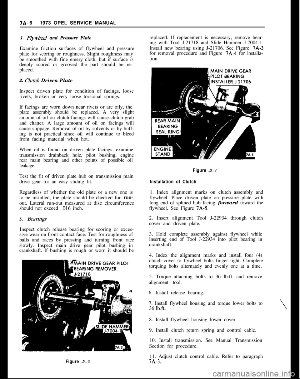
Inspect clutch release bearing for scoring or exces-
sive wear on front contact face. Test for roughness of
balls and races by pressing and turning front race
slowly. Inspect main drive gear pilot bushing in
crankshaft. If bushing is rough or worn it should be
Figure JA-3replaced. If replacement is necessary, remove bear-
ing with Tool J-21718 and Slide Hammer J-7004-1.
Install new bearing using J-21706. See Figure 7A-3
for removal procedure and Figure 7A-4 for installa-
tion.
\,,
Figure JA-4
Installation of Clutch1. Index alignment marks on clutch assembly and
flywheel. Place driven plate on pressure plate with
long end of splined hub facing forward toward the
flywheel. See Figure 7A-5.
2. Insert alignment Tool J-22934 through clutch
cover and driven plate.
3. Hold complete assembly against flywheel while
inserting end of Tool J-22934 into pilot bearing in
crankshaft.
4. Index the alignment marks and install four (4)
clutch cover to flywheel bolts finger tight. Complete
torquing bolts alternately and evenly one at a time.
5. Torque attaching bolts to 36 lb.ft. and remove
alignment tool.
6. Install release bearing.
7. Install flywheel housing and torque lower bolts to
36
lb.ft.8. Install flywheel housing lower cover.
9. Install clutch return spring and control cable.
10. Install transmission. See Manual Transmission
Section for procedure.
11. Adjust clutch control cable. Refer to paragraph7A-3.
Page 376 of 625
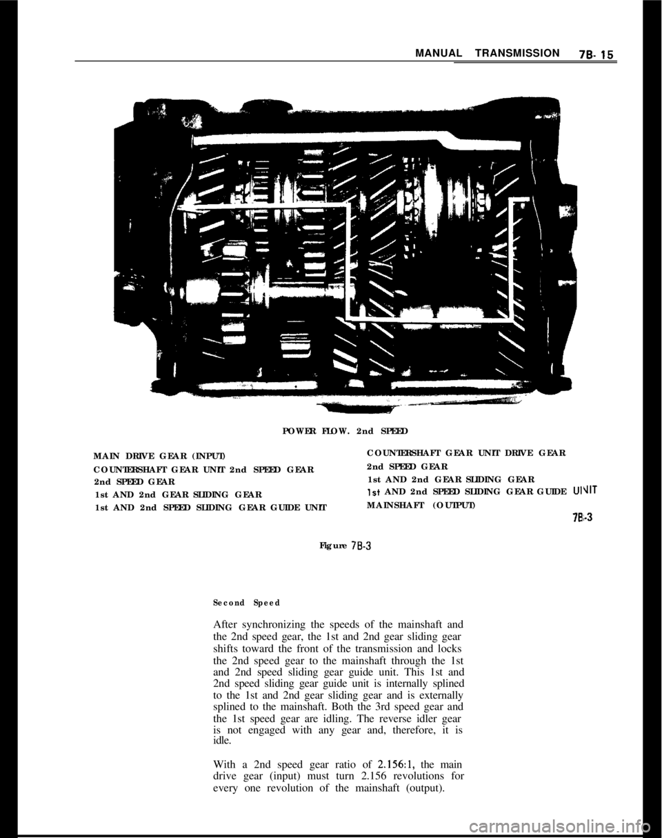
MANUAL TRANSMISSION76.15POWER FLOW. 2nd SPEED
MAIN DRIVE GEAR (INPUT)
COUNTERSHAFT GEAR UNIT 2nd SPEED GEAR
2nd SPEED GEAR
1st AND 2nd GEAR SLIDING GEAR
1st AND 2nd SPEED SLIDING GEAR GUIDE UNITCOUNTERSHAFT GEAR UNIT DRIVE GEAR
2nd SPEED GEAR
1st AND 2nd GEAR SLIDING GEAR
Ist AND 2nd SPEED SLIDING GEAR GUIDE UIMAINSHAFT (OUTPUT)
76Figure 78.3
Second SpeedAfter synchronizing the speeds of the mainshaft and
the 2nd speed gear, the 1st and 2nd gear sliding gear
shifts toward the front of the transmission and locks
the 2nd speed gear to the mainshaft through the 1st
and 2nd speed sliding gear guide unit. This 1st and
2nd speed sliding gear guide unit is internally splined
to the 1st and 2nd gear sliding gear and is externally
splined to the mainshaft. Both the 3rd speed gear and
the 1st speed gear are idling. The reverse idler gear
is not engaged with any gear and, therefore, it is
idle.
With a 2nd speed gear ratio of
2.156:1, the main
drive gear (input) must turn 2.156 revolutions for
every one revolution of the mainshaft (output).
VIT
i-3