OPEL GT-R 1973 Service Manual
Manufacturer: OPEL, Model Year: 1973, Model line: GT-R, Model: OPEL GT-R 1973Pages: 625, PDF Size: 17.22 MB
Page 491 of 625

7C-130
1973 OPEL SERVICE MANUAL
Figure 7C-2 17
into case. See Figure 7C-218. Use liberal amount of
transmission fluid on oil seal rings.
GOVERNOR
HUBFigure
7C-2 183. Install snap ring over output shaft using snap ring
pliers such as J-8059. See Figure
7C-219.4. Install new governor body gasket.
5. Bolt governor body to governor hub. Torque to 6-8
lbs. ft. The two governor valves should move freely
after governor body is torqued.
6. Install speedometer drive gear retaining clip into
output shaft. See Figure
7C-220.Figure 7C-219
Figure 7C-220
7. While depressing retaining clip, slide speedometer
gear over output shaft and install gear and retaining
clip.
Installation of Extension Housing
1. Install new extension housing gasket.
2. Slide extension housing over output shaft and
align holes.
3. Align parking
paw1 shaft into extension housing.
Page 492 of 625

AUTOMATIC TRANSMISSION 7C-1314. Bolt extension housing to rear of case. Torque to
20-30 Ibs. ft. See Figure
7C-221.
Figure 7C-22
1
Installation of Speedometer Driven Gear1. Install speedometer driven gear and housing into
extension housing. See Figure
7C-222.Figure 7C-222
2. Install speedometer driven gear housing retainer
into slot provided in speedometer driven gear hous-
ing. Bolt retainer to extension housing. Torque to
6-Slbs. ft. See Figure
7C-223.
installation of Detent Valve, Modulator Valve,
Modulator Assembly1. inspect detent valve sleeve oil seal and replace if
necessary.Figure 7C-223
2. Install detent valve, sleeve, spring, and spring seat
into case bore using liberal amount of transmission
fluid.
3. Depress detent valve spring and insert spring pin
to secure detent valve assembly. Detent valve sleeve
must be installed with slots facing oil pan. Care
should be taken so that spring pin is inserted into the
groove provided in sleeve and not into one of the oil
passage slots in the sleeve.
4. Install modulator valve and sleeve into case with
small end of modulator valve first.
5. Using new modulator assembly gasket, install
plunger and thread modulator into case and tighten
to
12-15 Ibs. ft. using tool J-23100. See Figure 7C-
224.
Installation and Adjustment of ServoAdjustment of servo can be performed with trans-
mission in vehicle.
1. Install servo apply rod, spring and piston into case,
using liberal amount of transmission fluid.
2. Compress servo piston spring using compressor
tool J-23075, lightly tapping servo piston while com-
pressing until piston is seated to avoid damage to the
oil seal ring.
3. Install servo retaining ring. See Figure
7C-225.Remove compressor tool J-23075.
Page 493 of 625

7C-1321973 OPEL SERVICE MANUAL
Figure 7C-226
Figure 7C.224
Figure 7C-225
4. Using 3/16” hex head wrench on servo adjusting
bolt, adjust servo apply rod by tightening adjusting
bolt to 40 lbs. in. Back off bolt five (5) turns. exact/u.See Figure
7C-226.5. Tighten lock nut holding adjusting bolt and sleeve
firm with hex head wrench. See Figure
7C-227.
installation of Valve Body
1. I&all steel balls in oil passages in case. See Figure
7C-228.Figure 7C-227
2. Install new case to transfer plate gasket.
3. Locate guide pins in transmission case for correct
alignment of valve body and transfer plate. See Fig-
ure
7C-229.4. Install manual valve into valve body bore using
liberal amount of transmission fluid.
5. Install long side of manual valve link pin into
manual valve. See Figure
7C-230.
Page 494 of 625

AUTOMATIC TRANSMISSION 7C-1338/Figure 7C-228
Figure 7C-229
6. Install small end of manual valve link “A” into
selector lever and install valve body and transfer
plate assembly over guide pins. See Figure
7C-23 1.
7. Install selector lever roller spring and retainer.
Torque to
13-15 lbs. ft. The valve body bolts should
be torqued starting in the center of the valve body
and working outward. Torque to 13-15
lbs. Ft.
8. Install reinforcement plate to case. Torque to
13-15 lbs. ft.9. Inspect oil strainer. If foreign matter is present,
install new strainer.
-VALV; BODY
x-220
Figure 7C-230
Figure
7C-231
10. Install oil strainer assembly using new gasket.
Torque to 13-15 Ibs. ft.
11. Install new servo cover gasket.
12. Install servo cover. Torque to 17-19 lbs. ft.
Installation of Oil Pan and Gasket1. Install new oil pan gasket.
2. Bolt oil pan to transmission case. Torque to 7-9
lbs. ft.
Page 495 of 625

7C-1341973 OPEL SERVICE MANUAL
Figure 7C-232
Torque Converter4. Rotate converter to check for free movement.
1. Place transmission on portable jack
2. Slide torque converter over stator shaft and input
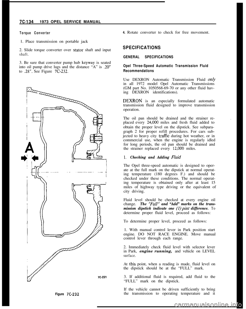
shaft.3. Be sure that converter pump hub keyway is seated
into oil pump drive lugs and the distance “A” is
.20”to
.28”. See Figure 7C-232.
SPECIFICATIONS
GENERAL SPECIFICATIONS
Opel Three-Speed Automatic Transmission Fluid
RecommendationsUse DEXRON Automatic Transmission Fluid on/y
in all 1972 model Opel Automatic Transmissions
(GM part No. 1050568-69-70 or any other fluid hav-
ing DEXRON identifications).DEXIRON is an especially formulated automatic
transmission fluid designed to improve transmission
operation.
The oil pan should be drained and the strainer re-
placed every
24,ooO miles and fresh fluid added to
obtain the proper level on the dipstick. See subpara-
graph 2 for proper refill procedures. For cars sub-
jected to heavy city
traff%z during hot weather, or in
commercial use, when the engine is regularly idled
for long periods, the oil pan should be drained and
the strainer replaced every
12,ooO miles.
.
1.Checking and Adding FluidThe Opel three-speed automatic is designed to oper-
ate at the full mark on the dipstick at normal operat-
ing temperature (180 degrees F.) and should be
checked under these conditions. The normal operat-
ing temperature is obtained only after at least 15
miles of highway type driving or the equivalent of
city driving.
Fluid level should be checked at every engine oil
change.
The “FuIl” and “Add” marks on the trans-
mission dipstick indicate one (1)pint
difference. Todetermine proper fluid level, proceed as follows:
To determine proper level, proceed as follows:
1. With manual control lever in Park position start
engine. DO NOT RACE ENGINE. Move manual
control lever through each range.
2. Immediately check fluid level with selector lever
in Park, engine running, and vehicle on LEVEL
surface.At
t,his point, when a reading is made, fluid level on
the dipstick should be at the “FULL” mark.
3. If additional fluid is required, add fluid to the
“FULL” mark on the dipstick.
If the vehicle cannot be driven sufficiently to bring
the transmission to operating temperature and it
Page 496 of 625

AUTOMATIC TRANSMISSION 7C-135
becomes necessary to check the fluid level, the trans-
mission may be checked at room temperature (70
degrees F.) as follows:
1. With manual control lever in Park position start
engine. DO NOT RACE ENGINE. Move manual
control lever through each range.
2. lmmediately check fluid level with selector lever
in Park, engine running, and vehicle on LEVEL sur-
face.At this point, when a reading is made, fluid level on
the dipstick should be I/4” below the “ADD” mark.
3. If additional fluid is required add fluid to bring
level to
l/4” below the “ADD” mark on the dip-
stick.If transmission fluid level is correctly established at
70 degrees F. it will appear at the “FULL” mark on
the dipstick when the transmission reaches normal
operating temperature (180 degrees F.) The fluid
level is set
l/4” below the “ADD” mark on the
dipstick to allow for expansion of the fluid which
occurs as transmission temperatures rise to normal
operating temperature of 180 degrees F.
Do not overfill, as foaming and loss of fluid through
the vent pipe might occur as fluid heats up. If fluid
is too low especially when cold, complete loss
of’drive may result which can cause transmission fail-
ure.
2.Draining oilpan and rep/a&g strainer assembly.
(a) Raise car on hoist or p/ace OnJxk stands, and
provide container to collect draining fluid.
(b) Remove oil pan and gasket. Discard gasket.
(c) Drain fluid from oil pan. Clean pan with solvent
and dry thoroughly with clean compressed air.
(d) Remove strainer assembly, strainer gasket and
discard.
(e) Install new oil strainer gasket. Install new strainer
assembly.
(f) Install new gasket on oil pan and install pan.
Tighten attaching bolts to 7-10 lb. ft.
(g) Lower car and add approximately three (3) pints
of transmission fluid through filler tube.
(h) With manual control lever in Park position, start
engine. DO NOT RACE ENGINE. Move manual
control lever through each range.
(i) Immediately check fluid level with selector leverin Park, engine running, and vehicle on LEVEL
sur-
face.(i) Add additional fluid to bring level to
l/4” below
the “ADD” mark on the dipstick. Do not overfill.
3.Adding Fluid to Fill Dry Transmission and Con-
verter Assembly
The fluid capacity of the Opel Three Speed Auto-
matic transmission and converter assembly is ap-
proximately IO-l/2 pints, but correct level is
determined by the mark on the dipstick rather than
by amount added. In cases of transmission overhaul,
when a complete fill is required, including a new
converter proceed as follows:
(a) Add approximately 10-l/2 pints of transmission
fluid through tiller tube.
The converter should be replaced on any major fail-
ure, such as a clutch or gearset, and an excessive
amount of foreign material is indicated in the pan. If
installation of a new converter is not required add
approximately five (5) pints of transmission fluid.
(b) With manual control lever in Park position start
engine and run at 1000 RPM. DO NOT RACE EN-
GINE. Move manual control lever through each
range.
(c) Immediately check fluid level with selector lever
in Park, engine running, and vehicle on LEVEL
sur-
face.(d) Add additional fluid to bring level to
l/4” below
the “ADD” mark on the dipstick. Do not overfill.
Opel Three Speed Automatic Transmission Towing
Instructions
If an Opel equipped with an automatic transmission
must be towed, the following precautions must be
observed:
The car may be towed safely on its rear wheels with
the shift lever in neutral position at speeds of 35 miles
per hour or less under most conditions.
However, the drive shaft must be disconnected or the
car towed on its front wheels if:
a. Tow speeds in excess of 35 mph are necessary.
b. Car must be towed for extended distances (over 50
miles).
c. Transmission is not operating properly.
If car is towed on its front wheels, the steering wheel
Page 497 of 625

7C-1361973 OPEL SERVICE MANUALshould be secured to keep the front wheels in a
straight-ahead position.sand,. mud, or snow, move the selector lever from
“D” to “R” in a repeat pattern while simultaneously
applying moderate pressure to the accelerator. DoRocking Carnot race engine. Avoid spinning wheels when trying
If it becomes necessary to rock the car to free it fromto free the car.
Model DesignationsTrans.
converterReverse Clutch
ModelAssemblyPlates Required2nd Gear
Clutch3rd Gear Clutch
Plates Required
Plates RequiredOpel
1900
OG
GT
CIHInformation
Drive
(Composition Faced:
Drive3Drive3
Green
(Composition
Faced)(CompositionFaced)
Dot ofDriven (Steel)4Driven (Steel) 4
Driven (Steel) 4
PaintWaved1Waved1Waved.1Pressure1Pressure1Pressure1-.
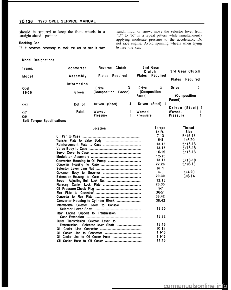
Bolt Torque Specifications
Location
Oil Pan to Case......................................................................Transfer Plate to Valve Body............................................
ReinforcementPlatetoCase..............................................
ValveBodytoCase..............................................................
ServoCovertoCase............................................................
Modulator Assembly............................................................
ConverterHousingtoOilPump........................................
Converter Housing to Case................................................
Selector Lever Jam Nut......................................................
Governor Body to Governor..............................................
ExtensionHousing to Case................................................
Servo AdjustingBolt Lock Nut..........................................
Planetary Carrier Lock Plate..............................................
OilPressureCheckPlug......................................................
Flex Plate to Crankshaft......................................................
Converter to Flex Plate........................................................
ConverterHousingtoCylinderBlock..............................
intermediate Selector Lever to Console
Selector Lever Shaft........................................................
Rear Engine Support to Transmission
CaseExtension..................................................................
Outer Transmission Selector Lever to
TransmissionSelectorLeverShaft..............................
Oil Cooler Line Connector..................................................
Oil Cooler Line to Connector............................................
Oil Cooler Line to Oil Cooler Hose..................................
Oil Cooler Hose to Oil Cooler............................................
Torque
Lb.Ft.7-10
6-8
13.15
13.1516-1812.15
13.17
22.26
8-l 1
6-8
20.30
12.15
20.35
5-736.5
138.42
38.42
Thread
Size
5/16-18
l/6-20
5/16-18
5/16-18
5/16-18
5/16-18
5/16-18
l/4-20
3/8-l 6
18.20
18.22
13.1610-13
1 l-15
1 l-15
11.15
Page 498 of 625

AUTOMATIC TRANSMISSION X-137F. OPEL AUTOMATIC TRANSMISSION LINKAGE ADJUSTMENTP
1. REMOVE LOCK CLIP
-‘\R
l2. PLACE SELECTOR LEVER IN
“r’ 0~ “1” POSITION
23. PLACE TRANSMISSION SHIFT LEVER IN “L” OR “1” POSITION
4. ADJUST CONTROL ROD (ALLOWING IT TO FIT OVER
PIN IN LOWER SELECTOR LEVER FREELY)
5. INSTALL LOCK CLIP
--_--_-SELECTORi--_-~-- GATE
\
\---
-x---i -__‘LACE SHIFT------
LEVER IN
“L” OR “I”
-.-
\/\SHIFT LEVER
L--________--7C-222Figure 7C-233 Adjusting Selector
Level
Page 499 of 625

7C.1381973 OPEL SERVICE MANUAL4
5
IFigure
7C-234 Special Tools. Automatic Transmission7C223
Page 500 of 625

AUTOMATIC TRANSMISSION 75139
SPECIAL TOOLSJ-8763-01
:: J-21369
3.J-8400-1
4.J-3289-20
5.J-23130-3
6.J-8092
7.J-21359
8.J-21426
9.J-2312910. J-7004
11. J-2590-12
12. J-21420-1
13. J-23130-7
14. J-23075
15. J-23 130-S16. J-231306
17. J-23130-1
18. J-21424-9
19.J-21465-17
20.J-23080
21.J-23 130-2
22.J-23082
23.J-23085
24.J-23 100Transmission Holding Fixture
Converter Leak Test Fixture
Cape ChiselHolding Fixture Base
Rear Case Bushing Remover and Installer
Driver Handle
Converter Housing Oil Seal Installer
Extension Housing Oil Seal Installer
Converter Housing Seal Remover
- Without Disassembling Transmission
(Use With J-7004)Slide Hammer
2nd and Reverse Clutch Piston Spring Compressor
Clutch Piston Compressor Adapter
Reaction Sun Gear Drum Bushing Sleeve Installer
Servo and 3rd Clutch Piston Spring Compressor
Oil Pump Bushing Remover
2nd Clutch Drum Bushing Remover and Installer
Oil Pump Bushing Installer
Extension Housing Bushing Remover and Installer (Use with J-8092
Driver Handle)
Converter Housing Bushing Remover and Installer (Use With J-8092)
2nd Clutch Piston Seal Installer
Reaction Sun Gear Drum Bushing Installer
Converter to Oil Pump Alignment Tool
Oil Pump to 2nd Clutch Drum Gauging Tool
Vacuum Modulator Wrench