OPEL GT-R 1973 Service Manual
Manufacturer: OPEL, Model Year: 1973, Model line: GT-R, Model: OPEL GT-R 1973Pages: 625, PDF Size: 17.22 MB
Page 531 of 625
9B-22 1973 OPEL SERVICE MANUAL
We can change a vapor back into a liquid by chilling
it, or do the same thing with pressure. When we
condense a vapor we will find that the heat removed
just exactly equals the amount of heat that was neces-
sary to make the substance vaporize in the first place.
At last the lost is found! The latent heat of vaporiza-
tion the heat that apparently disappeared when
a liquid boiled into a vapor again reappears on
the scene when that same vapor reverts back into a
liquid. It is just like putting air into a balloon to
expand it and then letting the same amount of air out
again to return the balloon to its original condition.
We know that any substance will condense at the
same temperature at which it boiled. This tempera-
ture point is a clear-cut division like a fence. On one
side, a substance is a liquid. Immediately on the
other side it is a vapor. Whichever way a substance
would go, from hot to cold or cold to hot, it will
change its character the moment it crosses over thefence.But pressure moves the fence! Water will boil at 212
degrees under normal conditions. Naturally, we ex-
pect steam to condense at the same temperature. But
whenever we put pressure on steam, it doesn’t! It will
condense at some temperature higher than 212 de-
grees. The greater the pressure, the higher the boiling
point and the temperature at which a vapor will
condense. This is the reason why pressure cookers
cook food faster, since the pressure on the water
permits it to boil out at a higher temperature. We
know that R-12 boils at 21.7 degrees below zero. A
thermometer will show us that the rising vapors,
even though they have soaked up lots of heat, are
only slightly warmer. But the vapors must be made
warmer than the room air if we expect heat to flow
out of them. Also, the condensing point temperature
must be above that of room air or else the vapors
won’t condense.This is where pressure comes to the rescue. With
pressure, we can compress the vapor, thereby con-
centrating the heat it contains. When we concentrate
heat in a vapor that way, we increase the intensity of
the heat or, in other words, we increase the tempera-ture;because temperature is merely a measurement
of heat intensity. And the most amazing part of it all
is that we’ve made the vapor hotter without actually
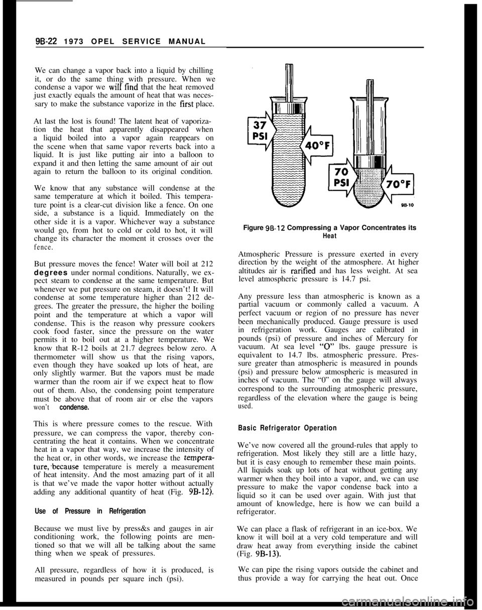
adding any additional quantity of heat (Fig.
9B-12).
Use of Pressure in RefrigerationBecause we must live by press&s and gauges in air
conditioning work, the following points are men-
tioned so that we will all be talking about the same
thing when we speak of pressures.
All pressure, regardless of how it is produced, is
measured in pounds per square inch (psi).Figure 98.12 Compressing a Vapor Concentrates its
HeatAtmospheric Pressure is pressure exerted in every
direction by the weight of the atmosphere. At higher
altitudes air is raritied and has less weight. At sea
level atmospheric pressure is 14.7 psi.
Any pressure less than atmospheric is known as a
partial vacuum or commonly called a vacuum. A
perfect vacuum or region of no pressure has never
been mechanically produced. Gauge pressure is used
in refrigeration work. Gauges are calibrated in
pounds (psi) of pressure and inches of Mercury for
vacuum. At sea level
“0” lbs. gauge pressure is
equivalent to 14.7 lbs. atmospheric pressure. Pres-
sure greater than atmospheric is measured in pounds
(psi) and pressure below atmospheric is measured in
inches of vacuum. The “0” on the gauge will always
correspond to the surrounding atmospheric pressure,
regardless of the elevation where the gauge is being
used.
Basic Refrigerator OperationWe’ve now covered all the ground-rules that apply to
refrigeration. Most likely they still are a little hazy,
but it is easy enough to remember these main points.
All liquids soak up lots of heat without getting any
warmer when they boil into a vapor, and, we can use
pressure to make the vapor condense back into a
liquid so it can be used over again. With just that
amount of knowledge, here is how we can build a
refrigerator.
We can place a flask of refrigerant in an ice-box. We
know it will boil at a very cold temperature and will
draw heat away from everything inside the cabinet
(Fig. 9B-13).
We can pipe the rising vapors outside the cabinet and
thus provide a way for carrying the heat out. Once
Page 532 of 625
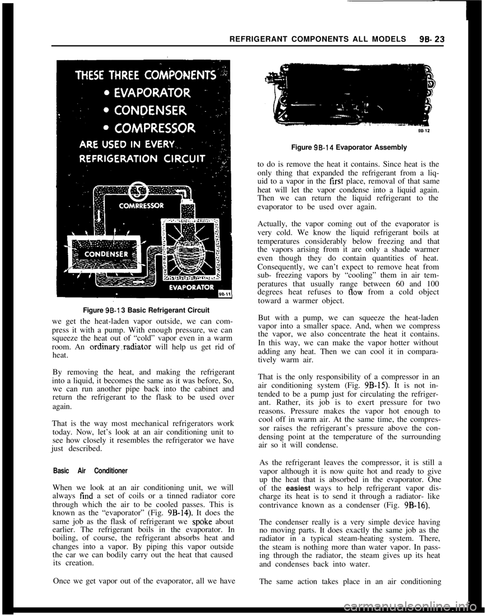
REFRIGERANT COMPONENTS ALL MODELS96.23Figure 96-l 3 Basic Refrigerant Circuit
we get the heat-laden vapor outside, we can com-
press it with a pump. With enough pressure, we can
squeeze the heat out of “cold” vapor even in a warm
room. An ordinary.radiator will help us get rid of
heat.
By removing the heat, and making the refrigerant
into a liquid, it becomes the same as it was before, So,
we can run another pipe back into the cabinet and
return the refrigerant to the flask to be used over
again.
That is the way most mechanical refrigerators work
today. Now, let’s look at an air conditioning unit to
see how closely it resembles the refrigerator we have
just described.
Basic Air ConditionerWhen we look at an air conditioning unit, we will
always find a set of coils or a tinned radiator core
through which the air to be cooled passes. This is
known as the “evaporator” (Fig.
9B-14). It does the
same job as the flask of refrigerant we
spok.e about
earlier. The refrigerant boils in the evaporator. In
boiling, of course, the refrigerant absorbs heat and
changes into a vapor. By piping this vapor outside
the car we can bodily carry out the heat that caused
its creation.
Once we get vapor out of the evaporator, all we haveFigure 98.14 Evaporator Assembly
to do is remove the heat it contains. Since heat is the
only thing that expanded the refrigerant from a liq-
uid to a vapor in the first place, removal of that same
heat will let the vapor condense into a liquid again.
Then we can return the liquid refrigerant to the
evaporator to be used over again.
Actually, the vapor coming out of the evaporator is
very cold. We know the liquid refrigerant boils at
temperatures considerably below freezing and that
the vapors arising from it are only a shade warmer
even though they do contain quantities of heat.
Consequently, we can’t expect to remove heat from
sub- freezing vapors by “cooling” them in air tem-
peratures that usually range between 60 and 100
degrees heat refuses to
flow from a cold object
toward a warmer object.
But with a pump, we can squeeze the heat-laden
vapor into a smaller space. And, when we compress
the vapor, we also concentrate the heat it contains.
In this way, we can make the vapor hotter without
adding any heat. Then we can cool it in compara-
tively warm air.
That is the only responsibility of a compressor in an
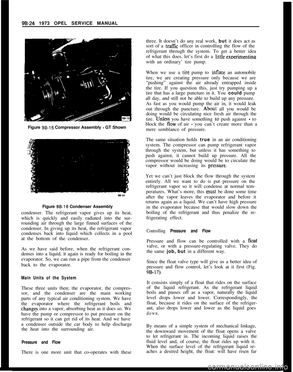
air conditioning system (Fig.
9B-15). It is not in-
tended to be a pump just for circulating the refriger-
ant. Rather, its job is to exert pressure for two
reasons. Pressure makes the vapor hot enough to
cool off in warm air. At the same time, the compres-
sor raises the refrigerant’s pressure above the con-
densing point at the temperature of the surrounding
air so it will condense.
As the refrigerant leaves the compressor, it is still a
vapor although it is now quite hot and ready to give
up the heat that is absorbed in the evaporator. One
of the easiest ways to help refrigerant vapor dis-
charge its heat is to send it through a radiator- like
contrivance known as a condenser (Fig. 9B-16).
The condenser really is a very simple device having
no moving parts. It does exactly the same job as the
radiator in a typical steam-heating system. There,
the steam is nothing more than water vapor. In pass-
ing through the radiator, the steam gives up its heat
and condenses back into water.
The same action takes place in an air conditioning
Page 533 of 625
9B-24 1973 OPEL SERVICE MANUAL
Figure 9B-15 Compressor Assembly - GT Shown
Figure 3B-16 Condenser Assembly
condenser. The refrigerant vapor gives up its heat,
which is quickly and easily radiated into the sur-
rounding air through the large finned surfaces of the
condenser. In giving up its heat, the refrigerant vapor
condenses back into liquid which collects in a pool
at the bottom of the condenser.
As we have said before, when the refrigerant con-
denses into a liquid, it again is ready for boiling in the
evaporator. So, we can run a pipe from the condenser
back to the evaporator.
Main Units of the SystemThese three units then; the evaporator, the compres-
sor, and the condenser are the main working
parts of any typical air conditioning system. We have
the evaporator where the refrigerant boils andchanges into a vapor, absorbing heat as it does so. We
have the pump or compressor to put pressure on the
refrigerant so it can get rid of its heat. And we have
a condenser outside the car body to help discharge
the heat into the surrounding air.
Pressure and FlowThere is one more unit that co-operates with thesethree. It doesn’t do any real work, but it does act as
sort of a traffic officer in controlling the flow of the
refrigerant through the system. To get a better idea
of what this does. let’s first do a li,ttle exoerimentine
with an ordinary’ tire pump.
When we use a
t,ire pump to Sate an automobile
tire, we are creating pressure only because we are
“pushing” against the air already entrapped inside
the tire. If you question this, just try pumping up a
tire that has a large puncture in it. You could pump
all day, and still not be able to build up any pressure.
As fast as you would pump the air in, it would leak
out through the puncture.
Abou~t all you would be
doing would be circulating nice fresh air through the
tire.
1Jnless you have something lo push against - to
block the tlow of air
- you can’t create more than a
mere semblance of pressure.
The same situation holds true in an air conditioning
system. The compressor can pump refrigerant vapor
through the system, but unless it has something to
push against, it cannot build up pressure. All the
compressor would be doing would be to circulate the
vapor without increasing its
pres,sure.Yet we can’t just block the flow through the system
entirely. All we want to do is put pressure on the
refrigerant vapor so it will condense at normal tem-
peratures. What’s more, this
musi: be done some time
after the vapor leaves the evaporator and before it
returns again as a liquid. We can’t have high pressure
in the evaporator because that would slow down the
boiling of the refrigerant and thus penalize the re-
frigerating effect.
Controlling Pressure and FlowPressure and flow can be controlled with a float
valve, or with a pressure-regulating valve. They do
the same job, but in a different way.
Since the float valve type will give us a better idea of
pressure and flow control, let’s look at it first (Fig.
9B-17).It consists simply of a float that rides on the surface
of the liquid refrigerant. As the refrigerant liquid
boils and passes off as a vapor, naturally the liquid
level drops lower and lower. Correspondingly, the
float, because it rides on the surface of the refriger-
ant, also drops lower and lower as the liquid goes
down.By means of a simple system of mechanical linkage,
the downward movement of the float opens a valve
to let refrigerant in. The incoming liquid raises the
fluid level and, of course, the float rides up with it.
When the surface level of the refrigerant liquid re-
aches a desired height, the float: will have risen far
Page 534 of 625
REFRIGERANT COMPONENTS ALL MODELS9B- 2596.15
Figure 95.17 Float Type Flow Valve
enough to close the valve and stop the flow of refrig-
erant liquid.
For the sake of simplicity, we have described the
float and valve action as being in a sort of definite
wide open or tight shut condition. Actually, though,
the liquid level falls rather slowly as the refrigerant
boils away. Likewise, the float goes down gradually
and gradually opens the valve just a crack. New
refrigerant liquid barely seeps in through the
“cracked” valve. At such a slow rate of flow, it raises
the liquid level in the evaporator very slowly.
With that in mind, it is easy to see how it would be
possible for a stabilized condition to exist. By that,
we mean a condition wherein the valve would be/
DIAPHRAGMACTUATINGBACK.UP PLATE
PINS \
t
>IAPHRAGM \
/
BoDyEQUALIZER\4]
PASSAGE
‘!!!ISEATSCkEEN:ARRIAGEORIFICE
AGE SPRINGIER ELEMENT:MOB”LBSPRING SEAT
OUTLET
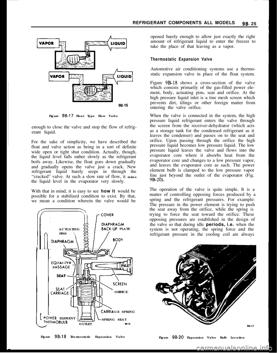
W-16opened barely enough to allow just exactly the right
amount of refrigerant liquid to enter the freezer to
take the place of that leaving as a vapor.
Thermostatic Expansion ValveAutomotive air conditioning systems use a thermo-
static expansion valve in place of the float system.
Figure 9B-18 shows a cross-section of the valve
which consists primarily of the gas-filled power ele-
ment, body, actuating pins, seat and orifice. At the
high pressure liquid inlet is a tine mesh screen which
prevents dirt, tilings or other foreign matter from
entering the valve orifice.
When the valve is connected in the system, the high
pressure liquid refrigerant enters the valve through
the screen from the receiver-dehydrator (which acts
as a storage tank for the condensed refrigerant as it
leaves the condenser) and passes on to the seat and
orifice. Upon passing through the orifice the high
pressure liquid becomes low pressure liquid. The low
pressure liquid leaves the valve and flows into the
evaporator core where it absorbs heat from the
evaporator core and changes to a low pressure vapor,
and leaves the evaporator core as such. The power
element bulb is clamped to the low pressure vapor
line just beyond the outlet of the evaporator (Fig.
9B-20).The operation of the valve is quite simple. It is a
matter of controlling opposing forces produced by a
spring and the refrigerant pressures. For example:
The pressure in the power element is trying to push
the seat away from the orifice, while the spring is
trying to force the seat toward the orifice. These
opposing pressures are established in the design of
the valve so that during idle periods, i.e. when the
system is not operating, the spring force and the
refrigerant pressure in the cooling coil are always
Figure 9B-18 Thermostatic Expansion Valve
Figure
98.20 Expansion Valve Bulb Location
Page 535 of 625
98-26 1973 OPEL SERVICE MANUAL
greater than the opposing pressure in the power ele-
ment. Therefore, the valve remains closed. When the
compressor is started, it will reduce the pressure and
temperature of the refrigerant in the cooling coil to
a point where the vapor pressure in the power ele-
ment becomes the stronger. The seat then moves off
the orifice and liquid starts to flow through the valve
orifice into the cooling coil.
The purpose of the power element is to help deter-
mine the quantity of liquid that is being metered into
the cooling coil. As the temperature of the low pres-
sure line changes at the bulb, the pressure of
the
vapor in the power element changes, resulting in a
change of the position of the seat. For example, if the
cooling coil gets more liquid than is required, the
temperature of the low pressure line is reduced and
the resultant lowering of the bulb temperature
reduces the pressure of the vapor in the power ele-
ment, allowing the seat to move closer to the orifice.
This immediately reduces the amount of liquid leav-
ing the valve. Under normal operation, the power
element provides accurate control of the quantity of
refrigerant to the cooling coil.
To employ our tire pump analogy once more for
clarity, it is the same situation that would exist if you were inflating a tire with a very slow leak. Providing
you pumped the air into the tire as fast as it leaked
out, you would be able to maintain pressure even
though the air would merely be circulating through the tire and leaking out through the puncture.
To Sum Up
So far, we’ve discussed only what each unit in an air
conditioning system does. We’ve learned that the
evaporator is the unit in which liquid refrigerant
soaks up heat from the air, the compressor is a pump
for squeezing this heat out of the vapor, the con-
denser is a radiator for getting rid of the heat, and the
thermostatic expansion valve is a device for regulat-
ing the pressure on the refrigerant. Now, let’s
find
out how the temperature of the cooled air is con-
trolled.
METHOD OF TEMPERATURE CONTROL
To achieve temperature control, the compressor is
run intermittently, automatically turning on and off
as necessary to maintain proper temperature.
Thermostatic Switch
The compressor can be started and stopped au-
tomatically through the use of an electro-magnetic
clutch and a thermostat affected by variations of temperature.
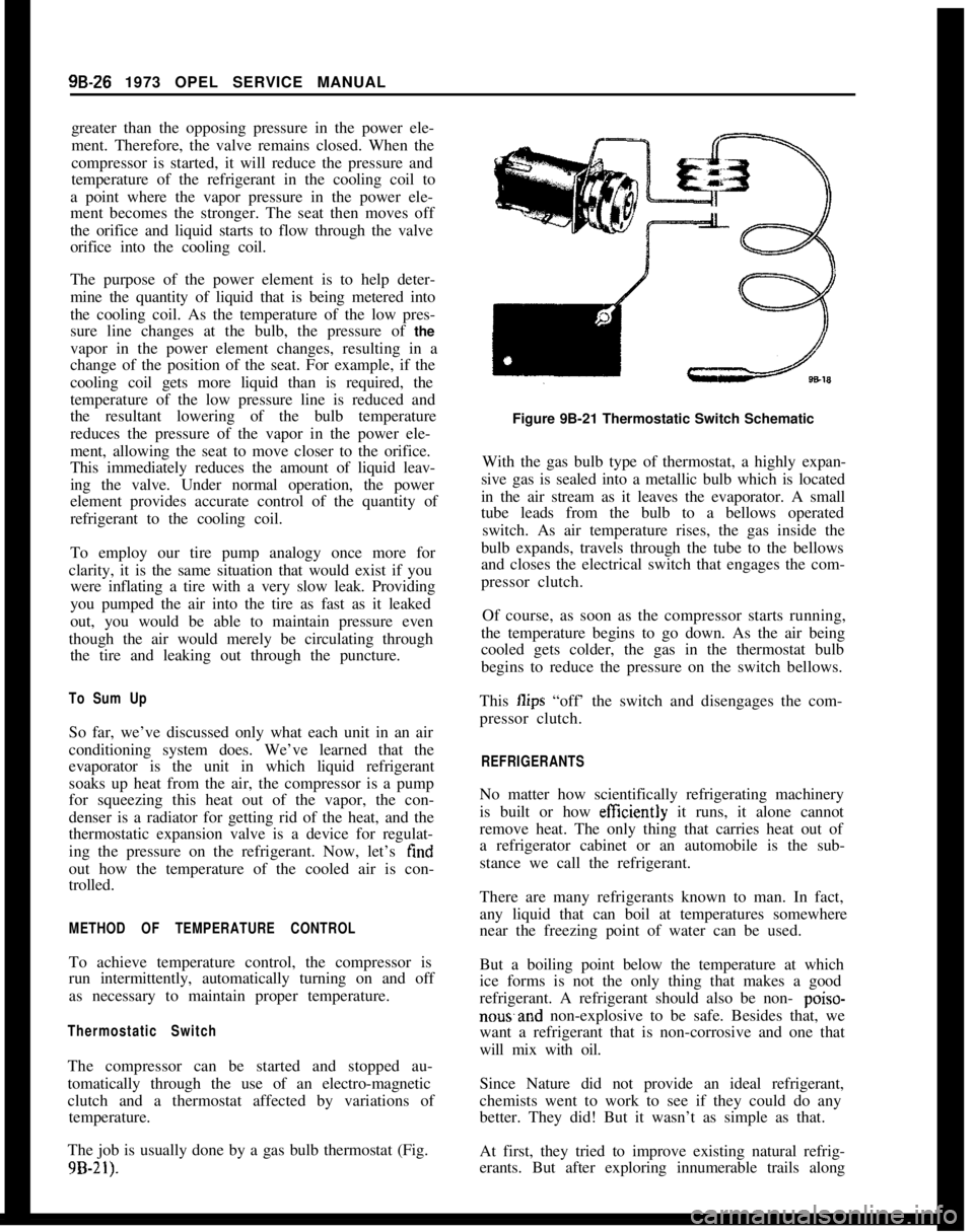
The job is usually done by a gas bulb thermostat (Fig.
9B-21).
Figure 9B-21 Thermostatic Switch Schematic
With the gas bulb type of thermostat, a highly expan-
sive gas is sealed into a metallic bulb which is located
in the air stream as it leaves the evaporator. A small
tube leads from the bulb to a bellows operated switch. As air temperature rises, the gas inside the
bulb expands, travels through the tube to the bellows
and closes the electrical switch that engages the com-
pressor clutch.
Of course, as soon as the compressor starts running,
the temperature begins to go down. As the air being
cooled gets colder, the gas in the thermostat bulb
begins to reduce the pressure on the switch bellows.
This
Ilips “off’ the switch and disengages the com-
pressor clutch.
REFRIGERANTS
No matter how scientifically refrigerating machinery
is built or how
efftciently it runs, it alone cannot
remove heat. The only thing that carries heat out of
a refrigerator cabinet or an automobile is the sub-
stance we call the refrigerant.
There are many refrigerants known to man. In fact,
any liquid that can boil at temperatures somewhere
near the freezing point of water can be used.
But a boiling point below the temperature at which
ice forms is not the only thing that makes a good
refrigerant. A refrigerant should also be non-
poiso-
nowand non-explosive to be safe. Besides that, we
want a refrigerant that is non-corrosive and one that
will mix with oil.
Since Nature did not provide an ideal refrigerant,
chemists went to work to see if they could do any
better. They did! But it wasn’t as simple as that.
At first, they tried to improve existing natural refrig-
erants. But after exploring innumerable trails along
Page 536 of 625

REFRIGERANT COMPONENTS ALL MODELS99.27that line, they still hadn’t gotten anywhere. So, they
started from scratch and juggled molecules around
to make an entirely new refrigerant. Eventually they
succeeded by remodeling the molecules in carbon
tetrachloride. This is the same fluid that is used in
fire extinguishers and dry-cleaners’ solvents.
From this fluid, the chemists removed two chlorine
atoms and replaced them with two fluorine atoms.
This newly-formed fluid carried the technical chemi-
cal name of dichlorodifluoromethane. Today, we
know it as Refrigerant-12 or R-12.
Fluorine is an extremely temperamental substance.
Under most conditions it is toxic and highly corro-
sive, and after is is manufactured, it has to be stored
in special containers because it will eat through glass
and will dissolve most metals in short order.
Despite its rambunctious character though, fluorine
is completely tamed when it is combined with the
other substances that go to make up the refrigerant.
Each is non-toxic, non-inflammable, non-explosive,
and non- poisonous; however, breathing large quan-
tities of R-12 should be avoided.
Pressure. Temperature Relationship of R-12A definite pressure and temperature relationship ex-
ists in the case of liquid refrigerants and their satu-
rated vapors. Increasing the temperature of a
substance causes it to expand. When the substance is
confined in a closed container, the increase in tem-
perature will be accompanied by an increase in pres-
sure, even though no mechanical device was used.
For every temperature, there will be a corresponding
pressure within the container of refrigerant. A table
of the temperature-pressure relationship of R-12 is
presented below. Pressures are indicated in gauge
pressure, either positive pressure (above atmos-
pheric) m pounds or negative pressure (below atmos-
pheric) in inches of vacuum.
“F-40
-35
i#Pressure
11.0*
8.3*
“F
50
50#Pressure
46.1
52.0
-30~
5.5*6057.7
-252.3*6s67 7__.
-200.6
io70.1
-152.4
76.9
-104.584.1
1;6.8 9.2tz99.6 91.71;
11.8 14.712116.9 108.1
1517.7105126.2
2021.1110136.0
2524.6115146.5
3028.5120157.1
;:
30.1
125167.5
32.6
131)179n
4037.0
4541.7*Inches of Vacuum.-. _.-
1402045
150232.0Thus if a gauge is attached to a container of R- 12 and
the room temperature is 70 degrees, the gauge will
register 70 psi pressure; in a 100 degrees room the
pressure will be 117
ps~
AIR CONDITIONINGBecause air conditioning has always been very
closely allied with mechanical refrigeration, most of
us are apt to think of it only as a process for cooling
room air.
But true air conditioning goes beyond the mere cool-
ing of the air. It controls the humidity, cleanliness,
and circulation of the air as well.
Whenever it gets warm and muggy in the summer-
time, someone is almost sure to say, “It’s not the heat
it’s the humidity.” But that is only partly right.
Actually it is a combination of the two that makes us
feel so warm temperature alone is not the only
thing that makes us uncomfortable.
Humidity is nothing more nor less that the moisture
content of the air. To a certain extent, it is tied in
with the temperature of the air. Warm air will hold
more moisture than will cold air. When air contains
all the moisture it can hold, we say it is saturated,
and the relative humidity is 100 percent. If the air
contains only half as much water as it could possibly
hold at any given temperature, we say that the rela-
tive humidity is 50 percent. If it contains only a fifth
of its maximum capacity, we say that the relative
humidity is 20 percent and so on. This amount
of water vapor, or relative humidity, affects the way
we perspire on hot days.
Nature has equipped our bodies with a network of
sweat glands that carry perspiration to the skin
sur-faces. Normally, this perspiration evaporates and, in
doing so, absorbs heat just like a refrigerant absorbs
heat when it is vaporized in a freezer. Most of the
heat thus absorbed is drawn from our bodies, giving
us a sensation of coolness. A drop of alcohol on the
back of your hand will demonstrate this principle
very convincingly. Because it is highly volatile, al-
cohol will evaporate very rapidly and absorb quite a
bit of heat in doing so, thereby making the spot on
your hand feel unusually cool.
The ease and rapidity with which evaporation takes
place, whether it be alcohol or perspiration, governs
our sensation of coolness and to a certain extent,
independently of the temperature. Of even more im-
portance, the ease and rapidity of the evaporation are
directly affected by the relative humidity or com-
parative dampness of the air. When the air is dry,
perspiration will evaporate quite readily. But when
the air contains a lot of moisture, perspiration will
evaporate more slowly; consequently less heat is car-
ried away from our body.
Page 537 of 625
9B-28 1973 OPEL SERVICE MANUAL
Thus, from the standpoint of comfort, complete air
conditioning should control the relative humidity of
the air as well as its temperature.
By reducing the humidity, we sometimes can be just
as “cool” in a higher room temperature than other-
wise would be comfortable. Laboratory tests have
shown that the average person will feel just as cool
in a temperature of 79 degrees when the relative
humidity is down around 30 percent as he will in a
cooler temperature of 72 degrees with a high relative
humidity of 90 percent.
There are practical limits though within which wemust stay when it comes to juggling humidity. For
human comfort, we can’t go much below a relative
humidity of 30 percent because anything lower than
that would cause an unpleasant and unhealthy dry-
ness in the throat and nasal passages.
Summertime temperatures of 85 degrees sometimes
bring with them relative humidities around 75 to 80
percent. Some coastal cities have relative humidities
averaging as high as 87 percent. To gain maximum
human comfort, an air conditioning system should
cool the air down and reduce the humidity to com-
fortable limits.
The cooling job usually is done just as it is in a
refrigerator. A compressor sends refrigerant through
a chilling unit where it absorbs heat. The heat is
drawn out of the air which circulates through the
chilling unit. Along with the cooling job it does, the
evaporator unit also removes much of the moisture
from the air. Everyone is familiar with the sight of
thick frost on the freezer of a refrigerator. That frost
is simply frozen moisture that has come out of the
air.
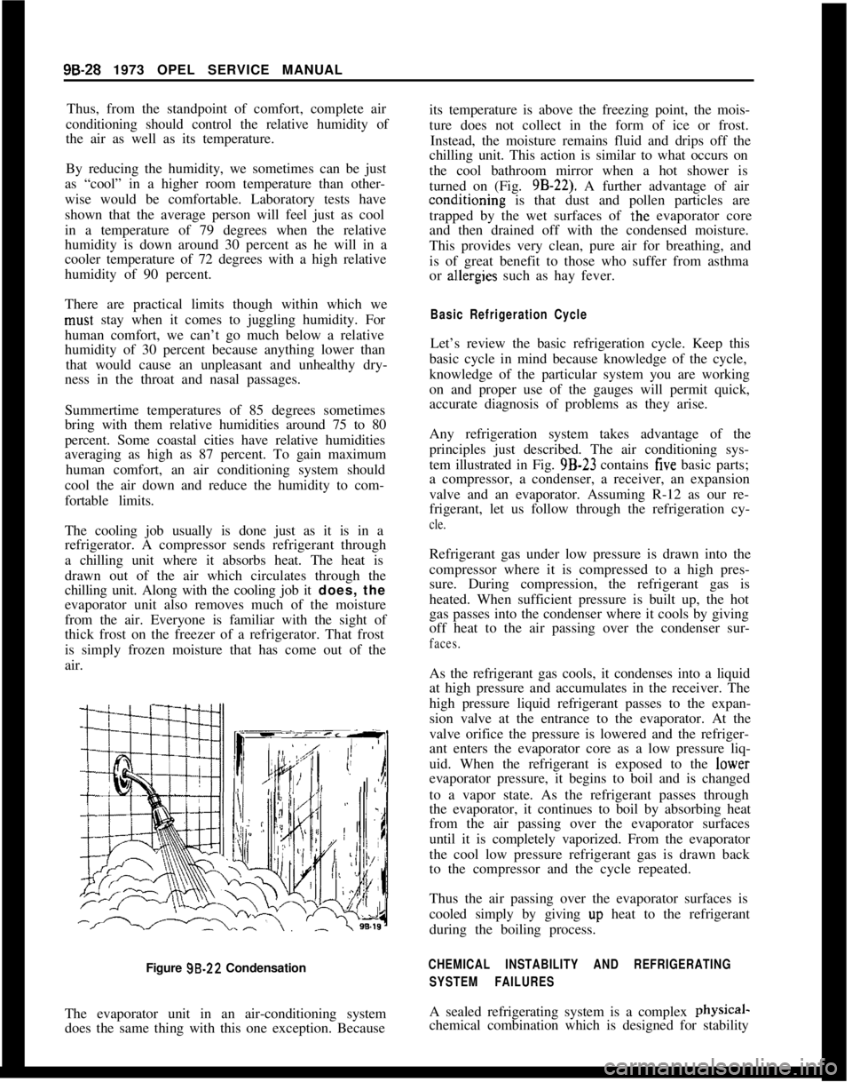
Figure 99.22 Condensation
The evaporator unit in an air-conditioning system
does the same thing with this one exception. Becauseits temperature is above the freezing point, the mois-
ture does not collect in the form of ice or frost.
Instead, the moisture remains fluid and drips off the
chilling unit. This action is similar to what occurs on
the cool bathroom mirror when a hot shower is
turned on (Fig. 9B-22). A further advantage of airconditioning is that dust and pollen particles are
trapped by the wet surfaces of
.the evaporator core
and then drained off with the condensed moisture.
This provides very clean, pure air for breathing, and
is of great benefit to those who suffer from asthma
or ahergies such as hay fever.
Basic Refrigeration CycleLet’s review the basic refrigeration cycle. Keep this
basic cycle in mind because knowledge of the cycle,
knowledge of the particular system you are working
on and proper use of the gauges will permit quick,
accurate diagnosis of problems as they arise.
Any refrigeration system takes advantage of the
principles just described. The air conditioning sys-
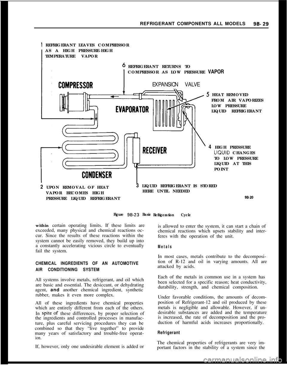
tem illustrated in Fig. 9B-23 contains
five basic parts;
a compressor, a condenser, a receiver, an expansion
valve and an evaporator. Assuming R-12 as our re-
frigerant, let us follow through the refrigeration cy-
cle.Refrigerant gas under low pressure is drawn into the
compressor where it is compressed to a high pres-
sure. During compression, the refrigerant gas is
heated. When sufficient pressure is built up, the hot
gas passes into the condenser where it cools by giving
off heat to the air passing over the condenser sur-
faces.As the refrigerant gas cools, it condenses into a liquid
at high pressure and accumulates in the receiver. The
high pressure liquid refrigerant passes to the expan-
sion valve at the entrance to the evaporator. At the
valve orifice the pressure is lowered and the refriger-
ant enters the evaporator core as a low pressure liq-
uid. When the refrigerant is exposed to the lower
evaporator pressure, it begins to boil and is changed
to a vapor state. As the refrigerant passes through
the evaporator, it continues to boil by absorbing heat
from the air passing over the evaporator surfaces
until it is completely vaporized. From the evaporator
the cool low pressure refrigerant gas is drawn back
to the compressor and the cycle repeated.
Thus the air passing over the evaporator surfaces is
cooled simply by giving up heat to the refrigerant
during the boiling process.
CHEMICAL INSTABILITY AND REFRIGERATING
SYSTEM FAILURESA sealed refrigerating system is a complex physical-
chemical combination which is designed for stability
Page 538 of 625
REFRIGERANT COMPONENTS ALL MODELS99.29
1 REFRIGERANT LEAVES COMPRESSOR
AS A HIGH PRESSURE-HIGH
TEMPERATURE VAPOR
REFRIGERANT RETURNS TO
COMPRESSOR AS LOW PRESSURE VAPOR
EXPANSION VALVE5 HEAT REMOVED
FROM AIR VAPORIZES
LOW PRESSURE
LIQUID REFRIGERANT
4 HIGH PRESSURE‘JQUID CHANGES
TO LOW PRESSURE
LIQUID AT THIS
POINT
2 UPON REMOVAL OF HEAT
VAPOR BECOMES HIGH
PRESSURE LIQUID REFRIGERANT3 LIQUID REFRIGERANT IS STORED
HERE UNTIL NEEDED
98*II
Figure 98-23
Basic
Refrigeration Cyclewithin certain operating limits. If these limits are
exceeded, many physical and chemical reactions oc-
cur. Since the results of these reactions within the
system cannot be easily removed, they build up into
a constantly accelerating vicious circle to eventually
fail the system.is allowed to enter the system, it can start a chain of
chemical reactions which upsets stability and inter-
feres with the operation of the unit.
Metals
CHEMICAL INGREDIENTS OF AN AUTOMOTIVE
AIR CONDITIONING SYSTEMAll systems involve metals, refrigerant, and oil which
are basic and essential. The desiccant, or dehydrating
agent, and another chemical ingredient, synthetic
rubber, makes it even more complex.
All of these ingredients have chemical properties
which are entirely different from each of the others.
In spite,of these differences, by proper selection of
the ingredients and controlled processes in manufac-
ture, plus careful servicing procedures they can be
combined so that they “live together” to provide
many years of satisfactory and trouble-free operat-
ion.If, however, only one undesirable element is added orIn most cases, metals contribute to the decomposi-
tion of R-12 and oil in varying amounts. All are
attacked by acids.
Each of the metals in common use in a system has
been selected for a specific reason; heat conductivity,
durability, strength, and chemical composition.
Under favorable conditions, the amounts of decom-
position of Refrigerant-12 and oil produced by these
metals is negligible and allowable. However, if un-
desirable substances are added and the temperature
is increased, the rate of decomposition and the pro-
duction of harmful acids increases proportionally.
RefrigerantThe chemical properties of refrigerants are very im-
portant factors in the stability of a system since the
Page 539 of 625
9B-30 1973 OPEL SERVICE MANUAL
refrigerant penetrates to every nook and cranny of
the unit.
Among the many desirable properties of R-12, is its
stability under operating conditions. However, while
more stable than the other refrigerants under the
same conditions, it, too, can be caused to form harm-
ful acids which will eventually fail the system.OilOil is the most complex of all of the organic chemi-
cals. Its stability in a refrigerating system is depend-
ent upon the source of crude oil and its method of
refining. A good refrigerating oil must be free of
sludge and gum-forming substances and free of
harmful impurities, such as sulphur. It must also be
stabilized to resist oxidation and must have a high
degree of resistance to carbonization.
The chemical properties of the lubricating oil form
another very important consideration in the chemi-
cal stability within the system. Like the refrigerant,
it travels to every nook and cranny of the unit.
The factory obtains the finest oils which have been
refined from the most desirable
crudes. It is reproc-
essed at the factory before it is charged into a system
or poured into a container for resale. Its
voscosityand flash point are checked and it is forced through
many sheets of filtering paper.
Even the containers in which it is poured for resale
are processed. As you recive it for field service it is
the cleanest, dry&, and purest oil that is humanly
possible to make. Leaving the container uncapped
even for a few minutes allows the oil to absorb mois-
ture from the air. Many system failures have been
caused by chemical reactions which were started by
servicemen adding contaminated oil.
Desiccants (Dehydrating Agent)Over the years the industry has spent hundreds of
thousands of dollars in finding and developing
chemical substances which are suitable for use in
refrigerating systems. An ideal desiccant must have
the following characteristics:
I. High capacity.
2. High eficiency.
3. Low tendency to powder.
4. Absorb moisture without reacting chemically with
it.5. Allow refrigerant to flow through it with mini-
mum restriction.
6. Retain moisture at high temperature.This has been a difficult combination to find. While
some desiccants excel in several of the desirable char-
acteristics, they are unsatisfactor:y in others.
Activated Silica Alumina, used in current
receiver-dehydrators, is a most satisfactory desiccant. How-
ever, its ability to retain moisture is affected by its
temperature. As the temperature increases, its ability
decreases. This means that moisture which is re-
tained at a lower temperature may be put back into
the system at a higher temperature.
MAINTAINING CHEMICAL STABILITY IN THE
REFRIGERATION SYSTEMThe metal internal parts of the refrigeration system
and the refrigerant and oil contained in the system
are designed to remain in a state of chemical stability
as long as pure R-12 plus refrigeration oil is used in
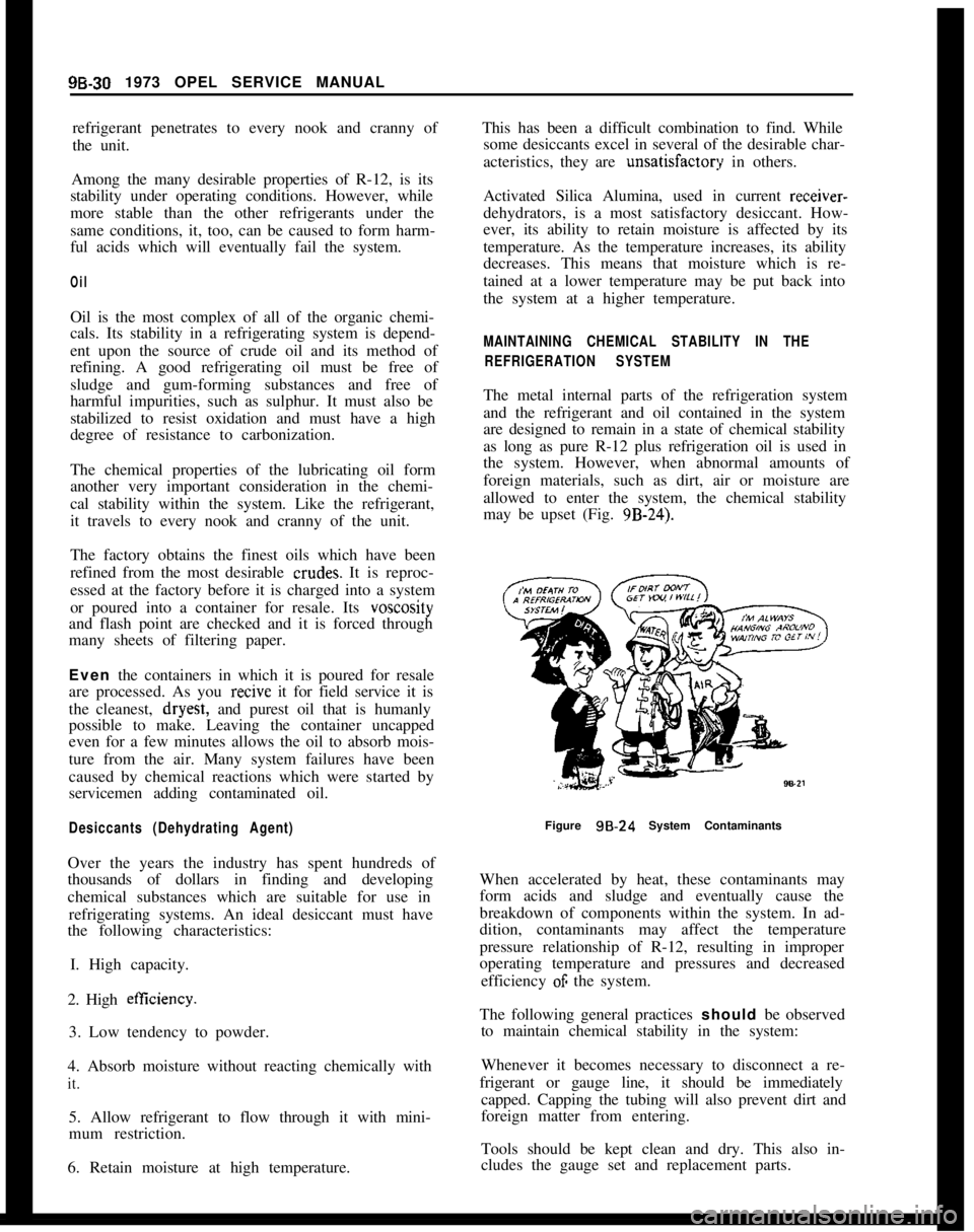
the system. However, when abnormal amounts of
foreign materials, such as dirt, air or moisture are
allowed to enter the system, the chemical stability
may be upset (Fig. 9B-24).
Figure
98.24 System Contaminants
When accelerated by heat, these contaminants may
form acids and sludge and eventually cause the
breakdown of components within the system. In ad-
dition, contaminants may affect the temperature
pressure relationship of R-12, resulting in improper
operating temperature and pressures and decreased
efficiency
OF the system.
The following general practices should be observed
to maintain chemical stability in the system:
Whenever it becomes necessary to disconnect a re-
frigerant or gauge line, it should be immediately
capped. Capping the tubing will also prevent dirt and
foreign matter from entering.
Tools should be kept clean and dry. This also in-
cludes the gauge set and replacement parts.
Page 540 of 625

REFRIGERANT COMPONENTS ALL MODELS9B- 31
When adding oil, the container should be exception-
ally clean and dry due to the fact that the refrigera-
tion oil in the container is as moisture-free as it is
possible to make it. Therefore, it will quickly absorb
any moisture with which it comes in contact. For this
same reason the oil container should not be opened
until ready for use and it should be capped immedi-
ately afte;r use.
When it is necessary to open a system, have every-
thing you will need ready and handy so that as little
time as possible will be required to perform the oper-
ation. Don’t leave the system open any longer than
is necessary.
Finally, after the operation has been completed and
the system sealed again, air and moisture should be
evacuated from the system before recharging.
THE PRIMARY CAUSES OF SYSTEM FAILURES
LeaksA shortage of refrigerant causes oil to be trapped in
the evaporator. Oil may be lost with the refrigerant
at point of leakage. Both of these can cause compres-
sor seizure.
Oil circulates in the system with the refrigerant; in
solution with the liquid and in globules with the
vapor. It leaves the compressor by the action of the
pistons and mixes with the refrigerant liquid in the
condenser. The oil then enters the evaporator with
the liquid and, with the evaporator properly flooded,
is returned to the compressor through the low pres-
sure line. Some of the oil returns as globules in the
vapor, but more important, it is swept as a liquid
along the walls of the tubing by the velocity of the
vapor. If the evaporator is starved, the oil cannot
return in sut?icient quantities to keep the compressor
properly lubricated.
High Temperature and PressureAn increase in temperature causes an increase in
pressure. This accelerates chemical instability due to
existing contaminants in the system, and initiates
chemical instability in clean systems. Other results
are brittle hoses,
“0” ring gaskets, and valve dia-
phragms with possible decomposition, broken com-
pressor discharge reeds, and seized compressor
bearings.
A fundamental law of nature accounts for the fact
that when a substance, such as a refrigerant, is in-
creased in temperature, its pressure is also increased.
Any chemical reactions caused by contaminants al-
ready in the system are greatly accelerated as the
temperature increases. A 15 degree rise in tempera-
ture doubles the chemical action. Even in a goodclean system, heat alone can start a chain of harmful
chemical reactions.
While temperature alone can cause the synthetic rub-
ber parts to become brittle and possibly to decom-
pose, the increased pressure can cause them to
rupture or blow.
As the temperature and pressure increases the stress
and strain on the compressor discharge reeds also
increases. This can result in broken reeds. Due to the
effect of the contaminants caused by high tempera-
ture and pressure, compressor bearings can be
caused to seize.
High temperature and pressure are also caused by air
in the system.
Air in the SYstemAir results from a discharged system or careless ser-
vicing procedures. This reduces system capacity and
efficiency and causes oxidation of oil into gum and
varnish.
When a leak causes the system to become dis-
charged, the resulting vacuum within the system will
cause air to be drawn in. Air in the system is a
non-condensable gas and will build up in the con-
denser as it would in an air compressor tank. The
resultant heat produced will contribute to the condi-
tions discussed previously.
Many systems are contaminated and also reduced in
capacity and efficiency by servicemen who either do
not know or are careless regarding proper servicing
procedures.
Too frequently, systems which have been open to the
atmosphere during service operations have not been
properly purged or evacuated. Air is also introduced
into the system by unpurged gauge and charging
lines. Remember that any air in the system is too
much air.
Poor ConnectionsHose clamp type fittings must be properly made.
Hoses should be installed over the sealing flanges and
with the end of the hose at the stop flange. The hose
should never extend beyond the stop flange. Locate
the clamp properly and torque as recommended. Be
especially careful that the sealing flanges are not
nicked or scored or a future leak will result.
When compression fittings are used, over tightening
can cause physical damage to the “0” ring gasket
and will result in leaks. The use of torque and back-
ing wrenches is highly recommended. When making
a connection with compression fittings, the gaskets
should always be first placed over the tube before