maintenance OPEL GT-R 1973 Repair Manual
[x] Cancel search | Manufacturer: OPEL, Model Year: 1973, Model line: GT-R, Model: OPEL GT-R 1973Pages: 625, PDF Size: 17.22 MB
Page 335 of 625

SE- 441973 OPEL SERVICE MANUAL
CARBURETOR AND THROTTLE LINKAGE
ALL MODELS
CONTENTS
Subject
DESCRIPTION AND OPERATION:
Carburetor
. . . . . . . . , . . . . . . . . . . . . . . . . . . . . . . . . . . . . . . . . . . . . . . . . . . . . . . . . . . . . . . . . . . . . . . . . . . .DIAGNOSIS:
Carburetor
. . . . . . . . . . . . . . . . . . . . . . . . . . . . . . . . . . . . . . . . . . . . . . . . . . . . . . . . . . . . . . . . . . . . . . . . . . . .MAINTENANCE AND ADJUSTMENTS:
Idle Speed and Mixture Adjustments
. . . . . . . . . . . . . . . . . . . . . . . .Fast Idle Speed Adjustment
. . . . . . . . . . . . . . . . . . . . . . . . . . . . . . . . . . . . . . . . . .Throttle Linkage Adjustment
. . . . . . . . . . . . . . . , . , . . . . . . . . . . . . . . . . . . . . . .MAJOR REPAIR:
RemoveandInstallCarburetor. . . . . . . . . . . . . . . . . . . . . . . . . . . . . . . . I...Throttle Linkage Removal
. . . . . . . . . . . . . . . . . . . . . . . . . . . . . . . . . . . . . . . . . . . . . .OverhaulCarburetor
. . . . . . . . . . . . . . . . . . . . . . . . . . . . . . . . . . . . . . . . . . . . . . . . . . . . . . . .SPECIFICATIONS:
Carburetor
Specifications
. . . . . . . . . . . . . . . . . . . . . . . . . . . . . . . . . . . . . . . . . . . . . . . .Page No.
6E-44
6E-49
6E-50
6E-51
6E-51
6E-52
6E-53
6E-53
6E-58
DESCRIPTION AND OPERATION
CARBURETORThe two-barrel carburetor for all 1973 Opel1
19G0,Manta and GT models is a down-draft carburetor
with two barrels of 1.25 inch diameter each. It has
an automatic choke and a secondary valve operated
by a vacuum diaphragm, except when installed in an
Opel GT. In the GT, the secondary throttle valve is
operated by mechanical linkage from the primary
throttle valve.
The two-barrel carburetor consists of three main
parts
- throttle body, float chamber and air horn.
Each barrel is a separate system, but both barrels
discharge into a common inlet in the intake mani-
fold. The secondary barrel does not have a choke
valve or an accelerator pump. See Figure
6E-2.The throttle valve of the primary barrel is opened
through the throttle linkage. When the primary
throttle valve is almost open, at approximately half
of the maximum engine RPM, the secondary throttlevalve is opened by vacuum applied through a
vacuum diaphragm case. See Figure
6E-3. The sec-
ondary throttle valve on the GT model is opened by
mechanical linkage from the primary throttle shaft.
Choke SystemThe automatic choke is operated by a bi-metal
spring. The tension of the spring
- depending on
temperature of the heater coil
- decreases with rising
temperature and the choke valve opens progressively
until it is completely opened at engine operating tem-
perature. The choke valve is off-set so that choke
valve opening increases as air flow increases.
If the choke valve is closed, the throttle valve is
opened slightly to provide a fast idle speed. This is
done through a cam, abutment lever and throttle
connecting link. With the throttle valve opened
slightly, the vacuum during cranking can take effect
up to the choke valve, thereby drawing ample fuel
out of the main nozzle. See Figure
6E-4.With rising temperature of the heater coil, the choke
Page 341 of 625
6E- 501973 OPEL SERVICE MANUALMAINTENANCE AND ADJUSTMENTS
IDLE SPEED ADJUSTMENT
Note:
Idle speeds of 600 to 800 R.P.M. are normal
for engines with less than
3,ooO miles.Prior to making any adjustment to the carburetor,
the following items must be checked for proper oper-
ation and/or setting:
1. Valve Adjustment (Hydraulic lifters can be im-
properly adjusted.)
2. Dwell Angle.
3. Ignition Timing.
4. Spark Plug Gap.
5. Exhaust Gas Recirculation Valve (See “Check-
ing” under EXHAUST GAS RECIRCULATION
SYSTEM.)
After it has been ascertained that the above items are
properly adjusted and operating correctly and idle
R.P.M. is still not within specifications, proceed as
follows:
1. With air cleaner installed, run engine until normal
operating temperature is reached.
2. Remove plastic caps from the idle mixture screw
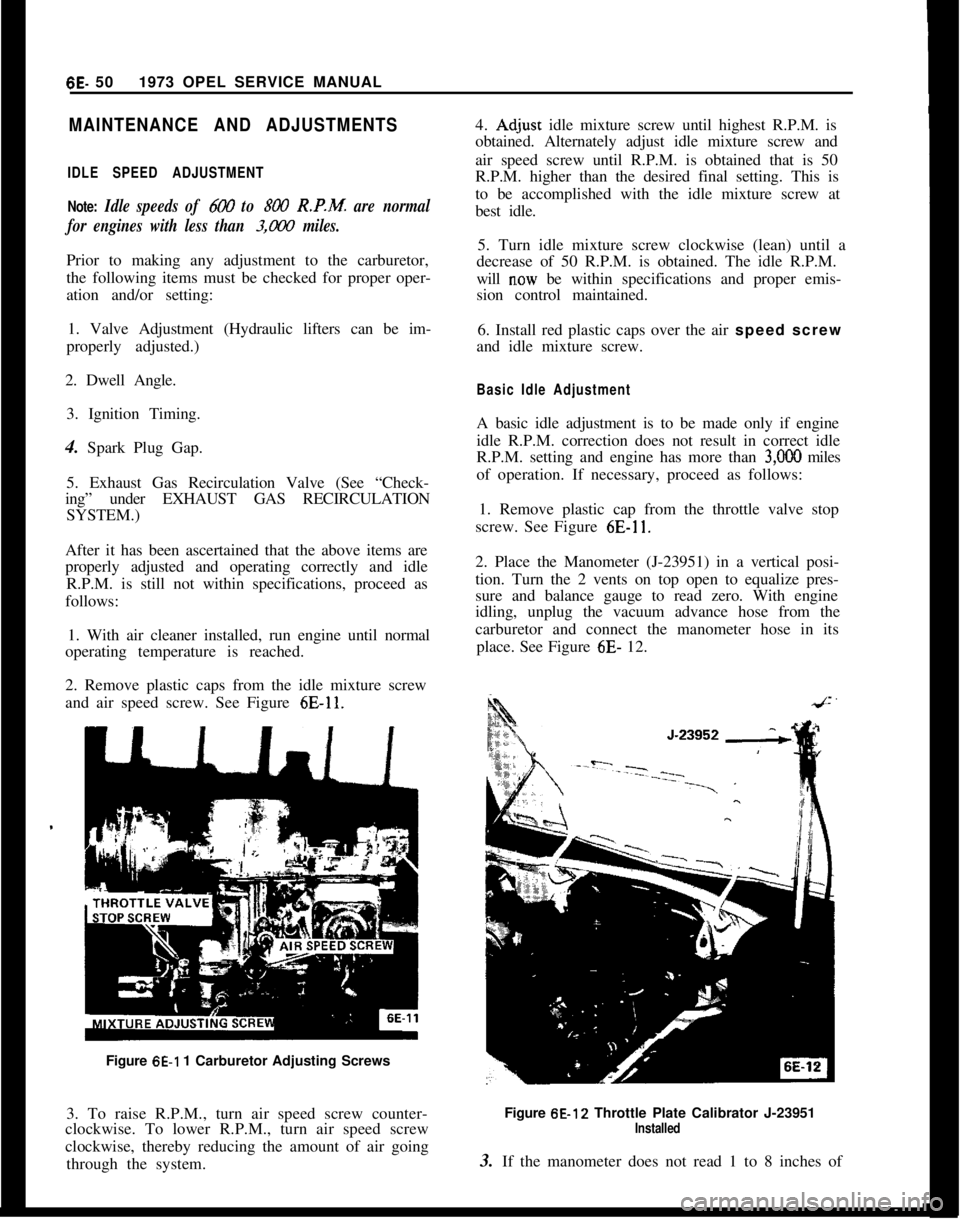
and air speed screw. See Figure
6E-11.Figure
6E-1 1 Carburetor Adjusting Screws
3. To raise R.P.M., turn air speed screw counter-
clockwise. To lower R.P.M., turn air speed screw
clockwise, thereby reducing the amount of air going
through the system.4.
Ad,just idle mixture screw until highest R.P.M. is
obtained. Alternately adjust idle mixture screw and
air speed screw until R.P.M. is obtained that is 50
R.P.M. higher than the desired final setting. This is
to be accomplished with the idle mixture screw at
best idle.
5. Turn idle mixture screw clockwise (lean) until a
decrease of 50 R.P.M. is obtained. The idle R.P.M.
will
n.ow be within specifications and proper emis-
sion control maintained.
6. Install red plastic caps over the air speed screw
and idle mixture screw.
Basic Idle AdjustmentA basic idle adjustment is to be made only if engine
idle R.P.M. correction does not result in correct idle
R.P.M. setting and engine has more than
3,OOO miles
of operation. If necessary, proceed as follows:
1. Remove plastic cap from the throttle valve stop
screw. See Figure
6E-11.2. Place the Manometer (J-23951) in a vertical posi-
tion. Turn the 2 vents on top open to equalize pres-
sure and balance gauge to read zero. With engine
idling, unplug the vacuum advance hose from the
carburetor and connect the manometer hose in its
place. See Figure 6E- 12.
Figure 6E-12 Throttle Plate Calibrator J-23951
Installed3. If the manometer does not read 1 to 8 inches of
Page 351 of 625
6F- 601973 OPEL SERVICE MANUAL
EMISSION CONTROL SYSTEMS
ALL MODELS
CONTENTS
Subject
DESCRIPTION AND OPERATION:
DescriptionandOperationofO.E.C.S.. . . . . . . . . . . . . . . . . . . . . . . .Exhaust
GasRecirculationSystem. . . . . . . . . . . . . . . . . . . . . . . . . . . . . .DIAGNOSIS:
Testing Therm0 Air Cleaner Operation
. . . . . . . . . . . . . . . . . . . . . .Exhaust
GasRecirculationSystem. . . . . . . . . . . . . . . . . . . . . . . . . . . . . .MAINTENANCE AND ADJUSTMENTS:
Exhaust GAS Recirculation System
. . . . . . . . . . . . . . . . . . . . . . . . . . . .MAJOR REPAIR:
Removal and Replacement of O.E.C.S. Units
. . . . . . . . . .SPECIFICATIONS:
Opel Emission Control System Specifications
. . . . . . . .Page No.
6F-60
6F-62
6F-62
6F-636F-636F-636F-64
DESCRIPTION AND OPERATION
OPEL EMISSION CONTROL SYSTEM (O.E.C.S.)All 1973 cars must be capable of passing certain tests
which measure the quantity of unburned impurities
in the exhaust system. Federal law places a limit on
the hydrocarbon and carbon monoxide emissions
from the exhaust system. The purpose of this law is
to keep the atmosphere cleaner, particularly in popu-
lous areas where these impurities add to the smog
problem. Basically, excessive exhaust emissions are
caused by incomplete combustion of the air-fuel mix-
ture in the cylinders.
The basic components of the OECS on the 1.9 liter
engines are (1) leaned out carburetion, (2) heated air
(except GT), and (3) tuned spark timing.
(1) The carburetor idle system is leaned out and
special features are incorporated into the carburetors
to make possible additional idle mixture adjustments
over and above those manufactured into the carbu-
retors.
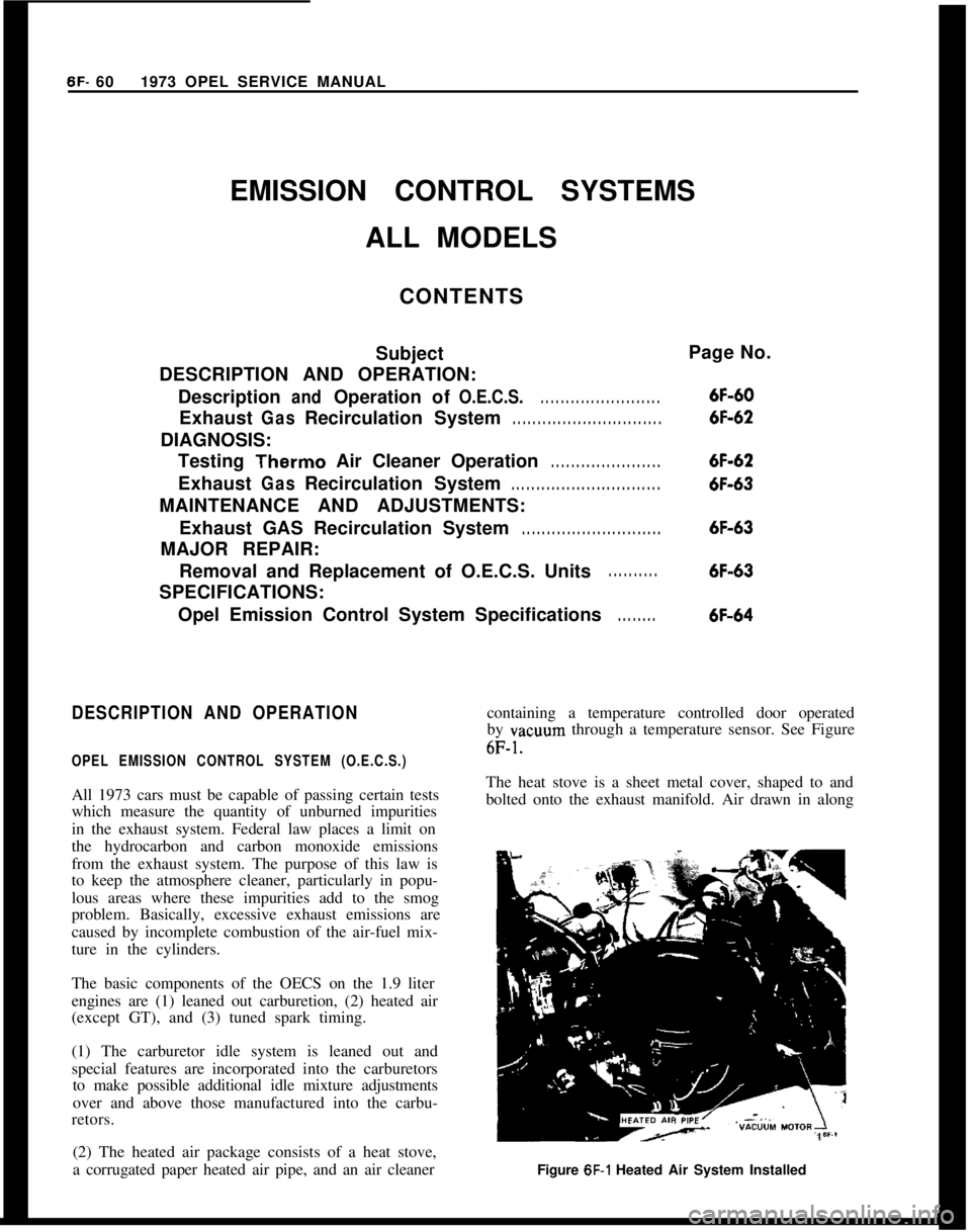
(2) The heated air package consists of a heat stove,
a corrugated paper heated air pipe, and an air cleanercontaining a temperature controlled door operated
by vacuum through a temperature sensor. See Figure6F-1.The heat stove is a sheet metal cover, shaped to and
bolted onto the exhaust manifold. Air drawn in along
Figure
6F-1 Heated Air System Installed
Page 354 of 625
EMISSION CONTROL SYSTEMS6F- 63
2. With the engine “OFF”, observe damper doorposition through snorkel opening. If position of snor-kel makes observation difficult “se the aid of a mir-
ror. At this point damper door should be in such a
position that the heat stove passage is covered (snor-
kel passage open). If not, check for binds in linkage.3. Apply at least nine in. Hg. of vacuum to dia-
phragm assembly through hose disconnected at sen-
sor “nit. This can be done by mouth. Damper door
should completely close snorkel passage whenvacuum is applied. If not, check to see if linkage is
hooked up correctly and for a vacuum leak.
4. With vacuum applied, bend or clamp hose to trapvacuum in diaphragm assembly. Damper door
should remain in position (closed snorkel passage). Ifit does not, there is a vacuum leak in diaphragm
assembly. Replace diaphragm assembly.
Sensor Check
Quick Check of System:
1. Start test with engine cold, air cleaner at a temper-ature below 85 degrees. If the engine has been in
recent “se, allow it to cool.
2. Observe the air door before starting the engine: it
should be closed.3. Start the engine and allow it to idle. Immediately
after starting the engine, the air door should open.
4. As the engine warms up, the air door should start
to close, and the air cleaner should become warm tothe hand.
5. The system is operating normally as described
above. If the air cleaner fails to operate as above or
if correct operation of the air cleaner is still in doubt,
proceed to the thermometer check.
Thermometer Check of Sensor:1. Start test with air cleaner temperature below 85
degrees. IF ENGINE HAS BEEN RUN RE-
CENTLY, ALLOW IT TO COOL DOWN. Whileengine is cooling, remove air cleaner cover and in-
stall a temperature gage such as J- 22973 as close as
possible to
se&r. Keinstall air cleaner cover. Let car
stand idle for
l/2 hour or more before proceeding to
step 2.2. Start the engine. Air door should open immedi-
ately if engine is cool enough. When air door starts
to close (in a few minutes), remove air cleaner cover
and read temperature gage. It must
read 115 degreesplus or minus 20 degrees.
3. If air door does not start to close at temperatureindicated, temperature sensor is defective and must
be replaced.
EXHAUST GAS RECIRCULATION SYSTEM
TestingThe exhaust gas recirculation valve is to be checked
at 12,000 mile intervals “sing the following proce-
dure:1. With engine at operating temperature, connect a
tachometer to engine and note R.P.M. at idle.
2. Disconnect vacuum hose at the intake manifold
that goes to the air cleaner.
3. Disconnect vacuum hose for exhaust gas recircula-tion valve from the throttle valve and connect it to
the intake manifold where vacuum hose to air
cleaner was connected.4. Engine speed should decrease between
100-240R.P.M. from previously noted R.P.M.
5. If the R.P.M. decrease is less than 100 R.P.M., theexhaust gas recirculation valve and fitting going into
the intake manifold must be removed, cleaned, and’
reinstalled.
MAINTENANCE AND ADJUSTMENTS
EXHAUST GAS RECIRCULATION SYSTEM
CleaningClean the exhaust gas recirculation valve and fitting
with a piece of stiff wire removing all exhaust depos-
its.
CAUTION:Do not soak in solvent. After
r.einstafIing the valve and fitting, check op
eration as outlined under “Testing”. If
vahe does not operate properly after a
thorough cleaning, replace it.
MAJOR REPAIR
REMOVAL AND REPLACEMENT OECS UNITSThe damper door is not serviceable. The air cleaner
assembly must be replaced if the damper door is
defective.
R And R Vacuum Motor
1. Remove vacuum
motor retainer spring. See Figure
6F-5.
Page 356 of 625
TUNE-UP
ALL MODELS
CONTENTS
Subject
DESCRIPTION AND OPERATION:
Purpose of a Tune-Up. . . . . . . . . . . . . . . . . . . . . . . . . . . . . . . . . . . . . . . . . . . . . . . . . , . . . .DIAGNOSIS: (Not Applicable)
MAINTENANCE AND ADJUSTMENTS:
EngineTune-UpMechanicalOperations. . . . . . . . . . . . . . . . . . . .
EngineTune-UpInstrumentChecks. . . . . . . . . . . . . . . . . . . . . . . . . . . .MAJOR REPAIR: (Not Applicable)
SPECIFICATIONS:
Tune-Uo Soecifications and Adjustments
. . . . . . . . . . . . . . . .Page No.6G-65
6G-6566-6766-68
DESCRIPTION AND OPERATION
PURPOSE OF TUNE-UP
The purpose of an engine tune-up is to restore powerand performance that may have been lost through,
loss of adjustment, wear, corrosion, or deterioration
of one or more parts or units. In the normal operat-
ion of an engine, these changes take place gradually
at quite a number of points so that it is seldom advis-able to attempt an improvement in performance by
correcting one or two items only. Time will be savedand more lasting results will be assured by following
a definite and thorough procedure of analysis and
correction of all items affecting power and perform-
ance. Because of Federal laws, limiting exhaust emis-sions, it is even more important that the engines
tune-up is done accurately, using the specifications
listed and the tune-up sticker found in each engine
compartment.
Economical, trouble free operation can better be as-sured if a complete tune-up is performed at first 4
months or
6,ooO miles of operation - then at 12
month or 12,000 mile intervals.
The parts or units which affect power and perform-
ance may be divided, into three groups (1) compres-sion, (2) ignition and (3) carburetion. The tune-up
procedure should cover these groups in the order
given. While the items affecting compression and
ignition may be handled according to individual
preference, correction of items in the carburetiongroup should not be attemplcu
ulllll all items in
compression and ignition have been satisfactorily
corrected.
MAINTENANCE AND ADJUSTMENTS
ENGINE TUNE-UP OPERATIONS
CompressionTo make sure hydrocarbon and carbon monoxide
emissions will be within limits, it is very important
that the adjustments be followed exactly.
The suggested procedure for engine tune-up is as
follows:1. Remove all spark plugs.
2. Position throttle and choke valve in full open posi-tion.
3. Connect jumper wire between distributor terminalof coil and ground on engine to avoid high tension
sparking while cranking engine.
4. Hook up starter remote control cable and turn
ignition switch to “on” position.
5. Firmly insert compression gage in spark plug port.Crank engine to obtain highest possible reading.
Page 362 of 625
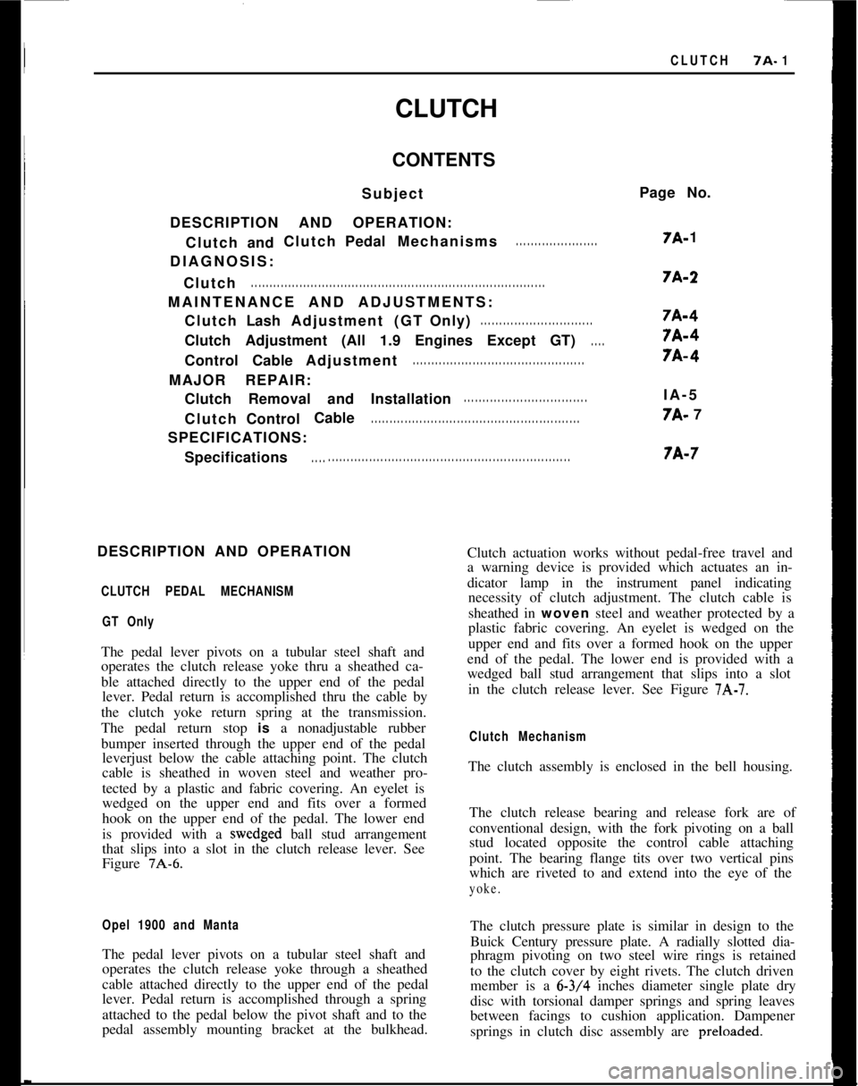
CLUTCH7A. 1
CLUTCH
CONTENTS
Subject
DESCRIPTION AND OPERATION: Clutch andClutch
PedalMechanisms
. . . . . . . . . . . . . . . . . . . . . .
DIAGNOSIS:
Clutch
. . . . . . . . . . . . . . . . . . . . . . . . . . . . . . . . . . . . \
. . . . . . . . . . . . . . . . . . . . . . . . . . . . . . . . . . . . \
. . . . . . .
MAINTENANCE AND ADJUSTMENTS: Clutch LashAdjustment (GTOnly)
. . . . . . . . . . . . . . . . . . . . . . . . . . . . . .
Clutch Adjustment (All 1.9 Engines Except GT). . . .
Control CableAdjustment. . . . . . . . . . . . . . . . . . . . . . . . . . . . . . . . . . . . \
. . . . . . . . . .
MAJOR REPAIR:
Clutch Removal and Installation
. . . . . . . . . . . . . . . . . . . . . . . . . . . . . . . . .
Clutch Control Cable. . . . . . . . . . . . . . . . . . . . . . . . . . . . . . . . . . . . \
. . . . . . . . . . . . . . . . . . . .
SPECIFICATIONS:
Specifications
. . . . . . . . . . . . . . . . . . . . . . . . . . . . . . . . . . . . . . . . \
. . . . . . . . . . . . . . . . . . . . . . . . . . . . .
Page No.
7A-
1
7A-2
7A-4
7A-4
7A-4
IA-5
7A- 7
7A-7
DESCRIPTION AND OPERATION
CLUTCH PEDAL MECHANISM GT Only
The pedal lever pivots on a tubular steel shaft and
operates the clutch release yoke thru a sheathed ca-
ble attached directly to the upper end of the pedallever. Pedal return is accomplished thru the cable by
the clutch yoke return spring at the transmission.
The pedal return stop
is a nonadjustable rubber
bumper inserted through the upper end of the pedal leverjust below the cable attaching point. The clutch
cable is sheathed in woven steel and weather pro-
tected by a plastic and fabric covering. An eyelet is
wedged on the upper end and fits over a formed
hook on the upper end of the pedal. The lower end
is provided with a
wedged ball stud arrangement
that slips into a slot in the clutch release lever. See
Figure
7A-6.
Opel 1900 and Manta
The pedal lever pivots on a tubular steel shaft and
operates the clutch release yoke through a sheathed
cable attached directly to the upper end of the pedal
lever. Pedal return is accomplished through a spring
attached to the pedal below the pivot shaft and to the
pedal assembly mounting bracket at the bulkhead. Clutch actuation works without pedal-free travel and
a warning device is provided which actuates an in-
dicator lamp in the instrument panel indicating
necessity of clutch adjustment. The clutch cable is
sheathed in
woven steel and weather protected by a
plastic fabric covering. An eyelet is wedged on the
upper end and fits over a formed hook on the upper
end of the pedal. The lower end is provided with a
wedged ball stud arrangement that slips into a slot in the clutch release lever. See Figure
7A-7.
Clutch Mechanism
The clutch assembly is enclosed in the bell housing.
The clutch release bearing and release fork are of
conventional design, with the fork pivoting on a ball
stud located opposite the control cable attaching
point. The bearing flange tits over two vertical pins
which are riveted to and extend into the eye of the
yoke.
The clutch pressure plate is similar in design to the
Buick Century pressure plate. A radially slotted dia-
phragm pivoting on two steel wire rings is retained
to the clutch cover by eight rivets. The clutch driven
member is a
6-3/4 inches diameter single plate dry
disc with torsional damper springs and spring leaves
between facings to cushion application. Dampener
springs in clutch disc assembly are
preloaded.
Page 365 of 625
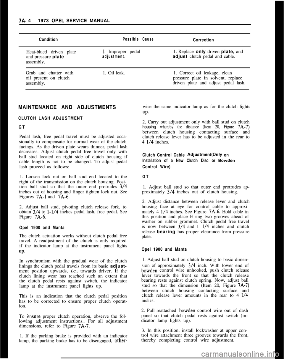
7A- 41973 dPEL SERVICE MANUALConditionPossible CauseCorrectionHeat-blued driven plate
and pressure plate
assembly.
1. Improper pedal1. Replace only driven plate, and
adjustment.adjust clutch pedal and cable.
Grab and chatter with
oil present on clutch
assembly.1. Oil leak.1. Correct oil leakage, clean
pressure plate in solvent, replace
driven plate and adjust pedal lash.
MAINTENANCE AND ADJUSTMENTS
CLUTCH LASH ADJUSTMENT
GTPedal lash, free pedal travel must be adjusted occa-
sionally to compensate for normal wear of the clutch
facings. As the driven plate wears thinner, pedal lash
decreases. Adjust clutch pedal free travel only with
ball stud located on right side of clutch housing if
cable length is not to be changed. To adjust pedal
lash proceed as follows:
1. Loosen lock nut on ball stud end located to the
right of the transmission on the clutch housing. Posi-
tion ball stud so that the outer end protrudes 3/4
inches out of housing and finger tighten lock nut. See
Figures
7A-1 and 7A-6.
2. Adjust ball stud, pivoting clutch release fork, to
obtain 3/4 to
l-1/4 inches pedal lash, free pedal. See
Figure 7A-6.
Opel 1900 and MantaThe clutch actuation works without clutch pedal free
travel. A readjustment of the clutch is only required
if the indicator lamp at the instrument panel lights
up.In synchronism with the gradual wear of the clutch
linings the clutch pedal travels from its basic adjust-
ment position upwards,
ie., towards driver. If the
clutch lining wear has reached such an extent that
the clutch pedal rests against switch, the indicator
lamp at the instrument panel lights up.
This is an indication that the clutch pedal position
has to be corrected to ensure proper clutch operat-
ion.
To
&~sure proper clutch operation, observe the fol-
lowing adjustment instructions.. For all adjustment
dimensions, refer to Figure 7A-7.
1. If the parking brake is provided with an indicator
lamp, the parking brake has to be disengaged, other-wise the same indicator lamp as for the clutch lights
UP.2. Carry out adjustment only with ball stud on clutch
housing whereby the distance (Item 20, Figure 7A-7)
between clutch housing contacting surface and
clutch release lever has to be adjusted in the rear to
4
l/4 inches.
Clutch Control Cable Adjustment(Only on
Installation of a New Clutch Disc or
Bowden
Control Wire)
GT1. Adjust ball stud so that outer end protrudes ap-
proximately 3/4 inches out of clutch housing.
2. Adjust distance between release lever and clutch
housing face at eye for control cable to approxi-
mately 4
l/4 inches. See Figure 7A-6. Hold cable in
this position and place E-ring two grooves ahead of
washer on rubber grommet. Clutch pedal free travel
is now between 3/4 and 1
l/4 inches and clutch
release bearing has proper clearance from pressure
plate.
Opel 1900 and Manta1. Adjust ball stud on clutch housing to basic dimen-
sion of approximately 3/4 inch. With lower end ofbowden control wire unhooked, push clutch release
lever towards the front so that the clutch release
bearing rests against clutch spring. Now, adjust ball
stud so that the dimension (Item 20, Figure
7A-7)between clutch housing contacting surface and
clutch release lever amounts in the rear to 4
l/4
inches.2. Pull reattached bowden control wire out of dash
panel so that clutch pedal rests against switch (in-
dicator lamp lights up).
3. In this position, install lockwasher at upper con-
trol wire attachment three grooves towards the front,
thereby completing control wire adjustment.
Page 373 of 625

7B- 121973 OPEL SERVICE MANUAL
MANUAL TRANSMISSION
CONTENTS
Subject
DESCRIPTION AND OPERATION:
Description. . . . . . . . . . . . . . . . . . . . . . . . . . . . . . . . . . . . . . . . . . . . . . . . . . . . . . . . . . . . . . . . . . . . . . . . . . . .Power
Flow. . . . . . . . . . . . . . . . . . . . . . . . . . . . . . . . . . . . . . . . . . . . . . . . . . . . . . . . . . . . . . . . . . . . . . . . . .DIAGNOSIS: (Not Applicable)
MAINTENANCE AND ADJUSTMENTS:
Adjusting
ReverseGearshiftBlocker. . . . . . . . . . . . . . . . . . . . . . . . . .Shift Lever Installation
. . . . . . . . . . . . . . . . . . . . . . . . . . . . . . . . . . . . . . . . . . . . . . . . .ServicingGearshift
Lever. . . . . . . . . . . . . . . . . . . . . . . . . . . . . . . . . . . . . . . . . . . . . . . .MAJOR REPAIR:
Transmission
Removal. . . . . . . . . . . . . . . . . . . . . . . . . . . . . . . . . . . . . . . . . . . . . . . . . . . . . .Installation
ofTransmission. . . . . . . . . . . . . . . . . . . . . . . . . . . . . . . . . . . . . . . . . .Removing and Installing
Speed0 Driven Gear
(Transmission
Removed). . . . . . . . . . . . . . . . . . . . . . . . . . . . . . . . . . . . . . . . . . . . . .
ReplacingBushinginSelectorLever. . . . . . . . . . . . . . . . . . . . . . . . . .Transmission
Disassembly. . . . . . . . . . . . . . . . . . . . . . . . . . . . . . . . . . . . . . . . . . . . . .Transmission
Reassembly. . . . . . . . . . . . . . . . . . . . . . . . . . . . . . . . . . . . . . . . . . . . . .SPECIFICATIONS:
Specifications ..,....._....,......,.....,......,.,.....,,.,..,......,.,....,........
Page No.
78-12
7B-13
78-1978-l
9
7B-19
78-22
78-22
78-23
78-23
78-23
78-28
78-33
Page 380 of 625

MANUAL TRANSMISSION76.19
DIAGNOSIS
MANUAL TRANSMISSION DIAGNOSIS
ConditionPossible CauseNoisy in Forward Speeds1) Low lubricant level.
2) Incorrect lubricant.
3) Transmission misaligned or loose.
4) Front main bearing worn or damaged.
5) Mainshaft bearing worn or damaged.
6) Countergear or bearings worn or damaged,
7) Main drive gear worn or damaged.
8) Synchronizers worn or damaged.
Noisy in “Reverse”1) Reverse sliding gear or shaft, worn or damaged
Hard Shifting1) Clutch improperly adjusted.
2) Shift shafts, or forks worn.
3) Incorrect lubricant.
4) Synchronizers worn or broken.
Jumping Out of Gear1) Partial engagement of gear.
2) Transmission misaligned or loose.
3) Worn pilot bearing.
4) End play in main drive gear (bearing retainer
loose or broken, loose or worn bearings on
main drive gear and mainshaft).
5) Worn clutch teeth on main drive gear and/or
worn clutch teeth on synchronizer sleeve.
6) Worn or broken blocking rings.
7) Bent mainshaft.
Sticking in Gear1) Clutch not releasing fully.
2) Low lubricant level.
3) Incorrect lubrication.
4) Defective (tight) main drive gear pilot
bearing.
5) Frozen blocking ring on main drive gear cone.
6) Burred or battered teeth on synchronizer
sleeve and/or main drive gear.
MAINTENANCE AND ADJUSTMENTS
ADJUSTING REVERSE GEARSHIFT BLOCKER1. Engage second speed.
2. Adjust selector ring (a) so that ball on lower end
of shift finger has an equal clearance on both sides
when seated into the transmission case extension bolt
hole. See Figure
7B-7.3. Back off selector ring an additional
l/4 of a turn
and tighten lock nut (B). See Figure
7B-7.SERVICING GEARSHIFT LEVER
Removal1. Unscrew console from floor panel, on small con-
sole remove three (3) attaching screws, on large con-
sole remove four (4) attaching screws. The fourth
screw is accessible after removal of the ash tray. See
Figure
7B-8.2. Remove rubber bellows from cover plate and from
below unbutton protective cap arranged around in-
termediate shift lever.
Page 397 of 625

7C- 361973 OPEL SERVICE MANUAL
CONTENTS
Subject
DESCRIPTION AND OPERATION:
Description of the Opel Three-Speed Automatic,Transmission....................................................................
Principles of Operation....................................................
ComponentOperation
andLocation............................
Mechanical Operation......................................................
Hydraulic Control Units and Valves............................H,y&aulic Operation..........................................................
DIAGNOSIS:
Sequence for Trouble Diagnosis..................................
Checking
Procedures........................................................
ExternalOil
Leaks..............................................................
Trouble
DiagnosisChart..................................................
Hydraulic Pressure
Checks............................................
MAINTENANCE AND ADJUSTMENTS:
Detent Cable Adjustment..............................................
ServicingSelector
Lever..................................................
MAJOR REPAIR:
Transmission Removal and Installation
AllModels........................................................................
Removalof
OilPan............................................................
RemovalofValveBody....................................................
Removalof
ServoPiston................................................
Removalof
Selector
LeverandShaft........................
RemovalofModulatorAssembly..................................
RemovalofDetentValveAssembly............................
RemovalofExtensionHousing......................................
Removal of Speedometer Drive Gear, Governor
Body and Governor Hub..............................................
Removal of Converter Housing, Oil Pump, Reverse
and Second Clutch Assembly..................................
Removal of Third Clutch Assembly, Planetary
Carrier Assembly, Reaction Sun Gear and Drum
Assembly and Low Bank............................................
Disassembly, Inspection and Reassembly of
Converter Housing, Oil Pump and Reverse Clutch
Disassembly, Inspection and Reassembly of
SecondClutch
................................................................
Disassembly, Inspection and Reassembly of
ThirdClutch....................................................................
Disassembly, Inspection and Reassembly of
Planetary Carrier
............................................................Page No.7c- 377c- 387c- 447c- 487c- 487c- 64
7C- 81
7C- 81IC- 817c- 827c- 877c- 917c- 937c- 947c- 99.7c- 99
7c-1007c-loo
7&l 01
7c-102
7c-102
7c-103
7c-103
7c-104
7c-105
7c-111
7c-114
7c-118