PONTIAC FIERO 1988 Service Repair Manual
Manufacturer: PONTIAC, Model Year: 1988, Model line: FIERO, Model: PONTIAC FIERO 1988Pages: 1825, PDF Size: 99.44 MB
Page 1731 of 1825
5H-18 DOORS - F STYLE
REFER TO ADJUSTMENT INSTRUCTIONS FOR
1 1 MODELING CLAY
STRIKER
IMPRESSION LOCK
FORK
BOLT
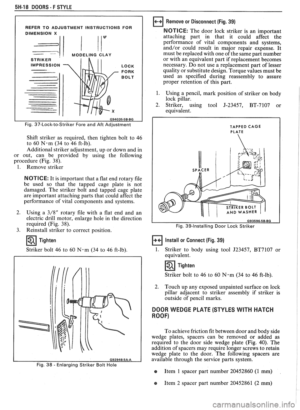
Fig. 37-Lock-to-Striker Fore and Aft Adjustment
Shift striker as required, then tighten bolt to 46
to 60
N-m (34 to 46 ft-lb).
Additional striker adjustment, up or down and in
or out, can be provided by using the following
procedure (Fig. 38).
1. Remove striker
NOTICE: It is important that a flat end rotary file
be used so that the tapped cage plate is not
damaged. The striker bolt and tapped cage plate
are important attaching parts that could affect the
performance of vital components and systems.
2. Using a
3/8" rotary file with a flat end and an
electric drill motor, enlarge hole in the direction
required (Fig. 38).
3. Reinstall striker to correct position.
Tighten
Striker bolt 46 to 60 N-m (34 to 46 ft-lb).
Fig. 38 - Enlarging Striker Bolt Hole
Remove or Disconnect (Fig. 39)
NOTICE: The door lock striker is an important
attaching part in that it could affect the
performance of vital components and systems,
and/or could result in major repair expense. It
must be replaced with one of the same part number
or with an equivalent part if replacement becomes
necessary. Do not use a replacement part of lesser
quality or substitute design. Torque values must be
used as specified during reassembly to assure
proper retention of this part.
1. Using a pencil, mark position of striker on body
lock pillar.
2. Striker, using tool J-23457,
BT-7107 or
equivalent.
TAPPED CAGE
PLATE
Fig. 39-Installing Door Lock Striker
Install or Connect (Fig. 39)
1.
Striker to body using tool J23457, BT7107 or
equivalent.
Tighten
Striker bolt to 46 to 60 N-m (34 to 46 ft-lb).
2. Touch up any exposed unpainted surface on lock
pillar adjacent to striker assembly if striker is
outside of pencil marks.
DOOR WEDGE PLATE (STYLES WITH HATCH
ROOF)
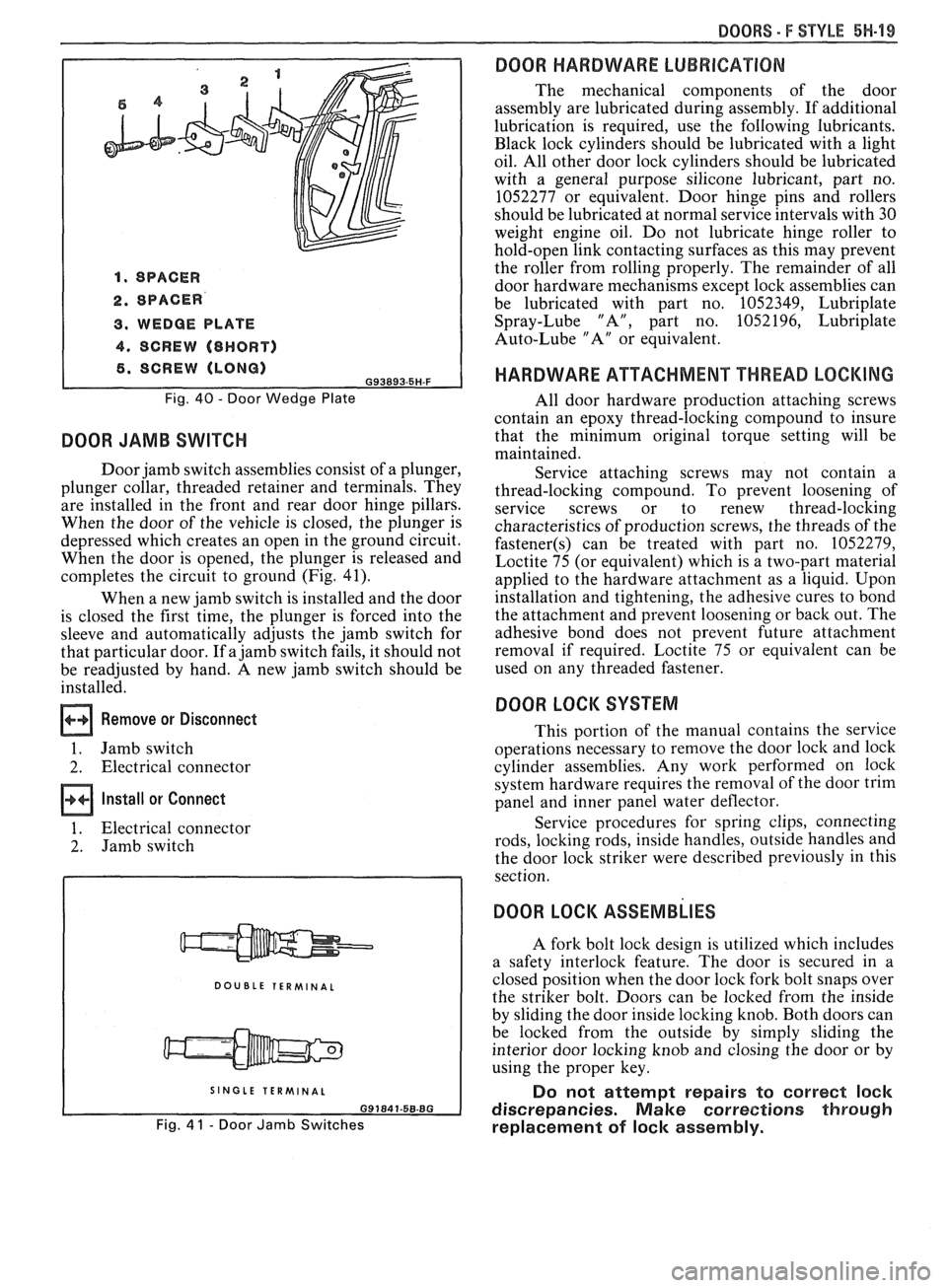
To achieve friction fit between door and body side
wedge plates, spacers can be removed or added as
required to the door side wedge plate (Fig. 40). The
addition of spacers may require longer screws to retain
wedge plate to the door. The following spacers are
available through the service parts system.
e Item 1 spacer part number 20452860 (1 mm)
e Item 2 spacer part number 20452861 (2 mm)
Page 1732 of 1825
DOORS - F STYLE 5H-99
1. SPACER
2. SPACER
3. WEDGE PLATE
4. SCREW (8HORT)
6. SCREW (LONG) G93893.5H-F
Fig. 40 - Door Wedge Plate
DOOR JAMB SWITCH
Door jamb switch assemblies consist of a plunger,
plunger collar, threaded retainer and terminals. They
are installed in the front and rear door hinge pillars.
When the door of the vehicle is closed, the plunger is
depressed which creates an open in the ground circuit.
When the door is opened, the plunger is released and
completes the circuit to ground (Fig. 41).
When a new jamb switch is installed and the door
is closed the first time, the plunger is forced into the
sleeve and automatically adjusts the jamb switch for
that particular door. If a jamb switch fails, it should not
be readjusted by hand. A new jamb switch should be
installed.
Remove or Disconnect
1. Jamb switch
2. Electrical connector
Install or Connect
1. Electrical connector
2. Jamb switch
DOUBLE TERMINAL
I SINGLE TERMINAL I
Fig. 4 1 - Door Jamb Switches
DOOR HARDWARE LUBRICATION
The mechanical components of the door
assembly are lubricated during assembly. If additional
lubrication is required, use the following lubricants.
Black lock cylinders should be lubricated with a light
oil. All other door lock cylinders should be lubricated
with a general purpose silicone lubricant, part no.
1052277 or equivalent. Door hinge pins and rollers
should be lubricated at normal service intervals with 30
weight engine oil. Do not lubricate hinge roller to
hold-open link contacting surfaces as this may prevent
the roller from rolling properly. The remainder of all
door hardware mechanisms except lock assemblies can
be lubricated with part no. 1052349, Lubriplate
Spray-Lube "A", part no. 1052196, Lubriplate
Auto-Lube "A" or equivalent.
HARDWARE ATTACHMENT THREAD LOCKING
All door hardware production attaching screws
contain an epoxy thread-locking compound to insure
that the minimum original torque setting will be
maintained.
Service attaching screws may not contain a
thread-locking compound. To prevent loosening of
service screws or to renew thread-locking
characteristics of production screws, the threads of the
fastener(s) can be treated with part no. 1052279,
Loctite 75 (or equivalent) which is a two-part material
applied to the hardware attachment as a liquid. Upon
installation and tightening, the adhesive cures to bond
the attachment and prevent loosening or back out. The
adhesive bond does not prevent future attachment
removal if required. Loctite 75 or equivalent can be
used on any threaded fastener.
DOOR LOCK SYSTEM
This portion of the manual contains the service
operations necessary to remove the door lock and lock
cylinder assemblies. Any work performed on lock
system hardware requires the removal of the door trim
panel and inner panel water deflector.
Service procedures for spring clips, connecting
rods, locking rods, inside handles, outside handles and
the door lock striker were described previously in this
section.
DOOR LOCK ASSEMBLIES
A fork bolt lock design is utilized which includes
a safety interlock feature. The door is secured in a
closed position when the door lock fork bolt snaps over
the striker bolt. Doors can be locked from the inside
by sliding the door inside locking knob. Both doors can
be locked from the outside by simply sliding the
interior door locking knob and closing the door or by
using the proper key.
Do not attempt repairs to correct lock
discrepancies. Make corrections through
replacement of lock assembly.
Page 1733 of 1825
5H-20 DOORS - F STYLE
Removal and Installation
1.
Raise door window. Remove door trim panel and
inner panel water deflector.
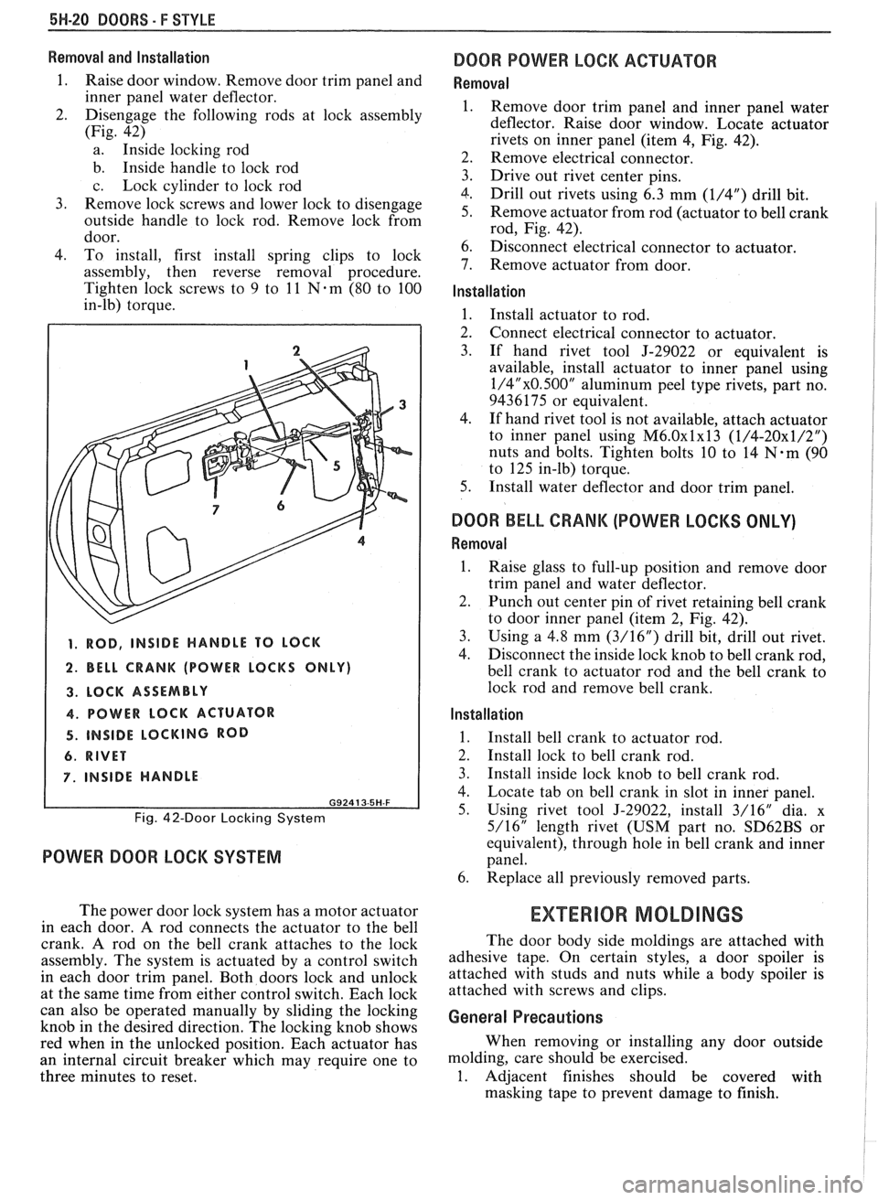
2. Disengage the following rods at lock assembly
(Fig. 42)
a. Inside locking rod
b. Inside handle to lock rod
c. Lock cylinder to lock rod
3. Remove lock screws and lower lock to disengage
outside handle to lock rod. Remove lock from
door.
4. To install, first install spring clips to lock
assembly, then reverse removal procedure.
Tighten lock screws to 9 to
11 Nem (80 to 100
in-lb) torque.
1. ROD, INSIDE HANDLE TO LOCK
2. BELL CRANK (POWER LOCKS ONLY)
3. LOCK ASSEMBLY
4. POWER LOCK ACTUATOR
4. INSIDE LOCKING ROD
6. RIVET
7. INSIDE HANDLE
G92413-5H-F
Fig. 42-Door Locking System
POWER DOOR LOCK SYSTEM
The power door lock system has a motor actuator
in each door.
A rod connects the actuator to the bell
crank. A rod on the bell crank attaches to the lock
assembly. The system is actuated by a control switch
in each door trim panel. Both doors lock and unlock
at the same time from either control switch. Each lock
can also be operated manually by sliding the locking
knob in the desired direction. The locking knob shows
red when in the unlocked position. Each actuator has
an internal circuit breaker which may require one to
three minutes to reset.
DOOR POWER LOCK ACTUATOR
Removal
Remove door trim panel and inner panel water
deflector. Raise door window. Locate actuator
rivets on inner panel (item
4, Fig. 42).
Remove electrical connector.
Drive out rivet center pins.
Drill out rivets using 6.3 mm
(1/4") drill bit.
Remove actuator from rod (actuator to bell crank
rod, Fig. 42).
Disconnect electrical connector to actuator.
Remove actuator from door.
Installation
1. Install actuator to rod.
2. Connect electrical connector to actuator.
3. If hand rivet tool J-29022 or equivalent is
available, install actuator to inner panel using
1/4"x0.500" aluminum peel type rivets, part no.
9436175 or equivalent.
4. If hand rivet tool is not available, attach actuator
to inner panel using
M6.0~1~13 (1/4-20x1/2")
nuts and bolts. Tighten bolts 10 to 14 N-m (90
to 125 in-lb) torque.
5. Install water deflector and door trim panel.
DOOR BELL CRANK (POWER LOCKS ONLY)
Removal
1.
Raise glass to full-up position and remove door
trim panel and water deflector.
2. Punch out center pin of rivet retaining bell crank
to door inner panel (item 2, Fig. 42).
3. Using a
4.8 mm (3/16") drill bit, drill out rivet.
4. Disconnect the inside
lock knob to bell crank rod,
bell crank to actuator rod and the bell crank to
lock rod and remove bell crank.
Installation
1.
Install bell crank to actuator rod.
2. Install lock to bell crank rod.
3. Install inside lock knob to bell crank rod.
4. Locate tab on bell crank in slot in inner panel.
5. Using rivet tool J-29022, install 3/16" dia. x
5/16" length rivet (USM part no.
SD62BS or
equivalent), through hole in bell crank and inner
panel.
6. Replace all previously removed parts.
EXTERIOR MOLDINGS
The door body side moldings are attached with
adhesive tape. On certain styles, a door spoiler is
attached with studs and nuts while a body spoiler is
attached with screws and clips.
General Precautions
When removing or installing any door outside
molding, care should be exercised.
1. Adjacent finishes should be covered with
masking tape to prevent damage to finish.
Page 1734 of 1825
DOORS - F STYLE 5H-21
2. Proper tools and care should be used to guard SPOILER ON BODY against molding damage.
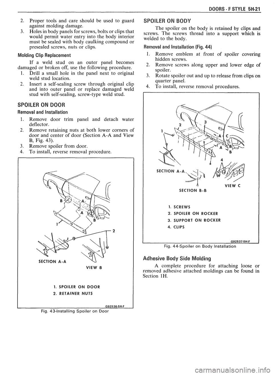
The spoiler on the body is retained by clips and
3.
~oles in body ~anels for screws, bolts or clips that screws, The screws thread into a support which is would permit water entry into the body interior welded to the body, must be sealed with bodv caulking. com~ound or " presealed screws, nuts or clips. Removal and Installation (Fig. 44)
Molding Clip Replacement 1. Remove emblem at front of spoiler covering
hidden screws.
If a stud On an Outer pane' becomes 2. Remove screws along upper and lower edge of damaged or broken off, use the following procedure.
spoiler.
1 Drill a small in the pane' next to 3. Rotate spoiler out and up to release from clips on weld stud location.
quarter panel.
2. Insert a self-sealing screw through original clip 4, To install, reverse removal procedures,
and into outer panel or replace damaged weld
stud with
self-sealing, screw-type weld stud.
SPOlLER ON DOOR
Removal and Installation
1. Remove door trim panel and detach water
deflector.
2. Remove retaining nuts at both lower corners of
door and center of door (Section
A-A and View
B, Fig. 43).
3. Remove spoiler from door.
4. To install, reverse removal procedure.
VIEW B
1. SPOILER ON BOOR
2. RETAINER NUTS
SECTION B-B
1. SCREWS
2. SPOILER ON ROCKER
3. SUPPORT ON ROCKER
Fig. 44-Spoiler on Body Installation
Adhesive Body Side Molding
A complete procedure for attaching loose or
removed adhesive attached moldings can be found in
Section
1H.
Fig. 43-Installing Spoiler on Door
Page 1735 of 1825

Page 1736 of 1825
REAR QUARTERS - F STYLE 8H-1
SECTION 6H
REAR QUARTERS
NOTICE: The anti-theft label found on some major sheet metal, engines, and transmissions must be masked
prior to painting, rustproofing, undercoating, etc. The mask
must be removed following the above operations.
Failure to keep the label clean and readable may result in liability for violation of Federal Vehicle Theft Prevention
Standard, and subject the vehicle owner to possible suspicion that the part was stolen.
CONTENTS
Quarter Trim .................................................... 6H- 1
Lower Trim Finishing Panel ....................... 6H- 1
Body Lock Pillar Trim Finishing
Panel
., ....................................................... 6H- 1
Upper Trim Finishing Panel Insert ............. 6H- 1
....................................................... Speakers 6H- 1
Lift Window Upper Finishing
Molding
..................................................... 6H-2
....................... Upper Trim Finishing Panel 6H-2
QUARTER TRlM
QUARTER LOWER TRlM FINISHING PANEL
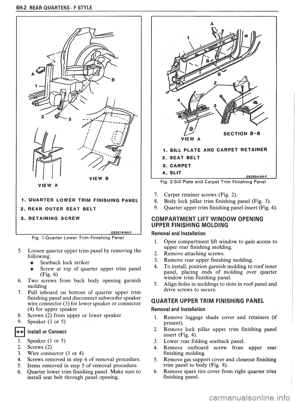
Removal and Installation (Fig. 1)
Remove body lock pillar finishing panel (Fig. 3).
Remove rear
seatback lock striker.
Remove retaining screw in rearward area of
quarter lower trim panel.
Remove rear screws from sill plate and carpet
retainer (Fig.
2).
Grasp quarter lower trim panel with hand; then
pull forward and down to disengage from
pinchweld flange at weatherstrip and quarter
upper trim finishing panel.
Remove seat belt through slot in trim panel.
Remove quarter lower trim finishing panel from
car by lifting up on rear portion of sill plate and
carpet retainer; then pull quarter trim rearward.
To install, place panel retaining slots under
quarter upper trim panel and apply upward
pressure to secure.
Position panel assembly to body. Thread lap and
shoulder belt through respective slots in panel.
Install attaching screws to secure panel to body.
Replace all previously removed components.
BODY LOCK PILLAR TRlM FINISHING PANEL
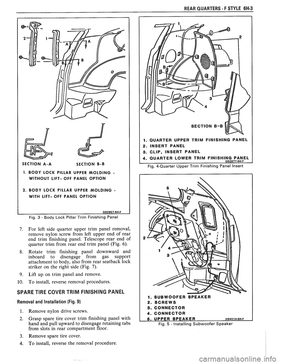
Removal and lnstallation (Fig. 3)
1. Remove trim panel attaching screws.
2. Using trim removing tool J-24595B, BT-7323A
or equivalent, carefully disengage nylon fasteners
that retain body lock pillar panel to quarter upper
trim finishing panel.
3. To install, reverse removal procedures. Spare
Tire Cover Trim Finishing
Panel
........................................................ 6H-3
Rear Stowage Compartment Box
Assembly
................................................... 6H-4
Luggage Shade Cover Assembly
................. 6H-4
Exterior Moldings
........................................... 6H-6
Fuel Tank Filler Door and Pocket
Assembly
....................................................... 6H-7
Spoiler Extension
............................ .. ........... 6H-7
QUARTER UPPER TRlM FINISHING PANEL
INSERT
Removal and Installation (Fig. 4)
1. Remove coat hook.
2. Grasp panel insert with hand and pull upward to
disengage retainers from cutout slots in quarter
upper trim finishing panel (Fig. 4).
3. To install, reverse removal procedures.
REAR QUARTER SPEAKERS
The rear quarter speakers are installed to a
speaker retainer. The retainer and speaker are then
attached to the quarter inner panel by screws.
Standard Speakers
Remove or Disconnect
1. Quarter upper trim finishing panel insert
2. Screws securing speaker retainer
3. Disconnect electrical
connector from speaker
4. Speaker
Install or Connect
1. Speaker to body
2. Electrical connector
3. Screws securing speaker to retainer
4. Quarter upper trim finishing panel insert
Subwoofer Speakers (2FS/FW/FX Styles)
Remove or Disconnect (Fig. 5)
1.
Quarter upper trim finishing panel insert (Fig. 4)
2. Body lock pillar trim finishing panel (Fig. 3)
3. Two rear screws from carpet retainer (Fig.
2)
4.
Quarter lower trim finishing panel
Page 1737 of 1825
661-2 REAR QUARTERS - F STYLE
"1 QUARTER LOWER TRIM FINISHING PANEL
2. REAR OUTER SEAT BELT
3. RETAINING SCREW
Fig. I-Quarter Lower Trim Finishing Panel
5. Loosen quarter upper trim panel by removing the
following:
e Seatback lock striker
@ Screw at top of quarter upper trim panel
(Fig. 6)
6. Two screws from back body opening garnish
molding
7. Pull inboard on bottom of quarter upper trim
finishing panel and disconnect subwoofer speaker
wire connector (3) for lower speaker or connector
(4) for upper speaker
8. Screws (2) from upper or lower speaker
9. Speaker (1 or 5)
Install or Connect
1. Speaker (1 or 5)
2. Screws (2)
3. Wire connector
(3 or 4)
4. Screws removed
in step 6 of removal procedure.
5. Items removed in step 5 of removal procedure.
6. Quarter lower trim finishing panel. Make sure to
install seat belt through panel opening.
'@ ,:'
{.-J SECTION B-I)
VIEW A
I. SILL PLATE AND CARPET RETAINER
4. SEAT BELT
9. CARPET
Fig. 2-Sill Plate and Carpet Trim Finishing Panel
7. Carpet retainer screws (Fig. 2).
8. Body lock pillar trim finishing panel (Fig. 3).
9. Quarter upper trim finishing panel insert (Fig. 4).
COMPARTMENT LIFT WINDOW OPENING
UPPER
FINISHING MOLDING
Removal and lnstallation
1. Open compartment lift window to gain access to
upper rear finishing molding.
2. Remove attaching screws.
3. Remove rear upper
finishing molding.
4. To
install, position garnish molding to roof inner
panel, placing ends of molding over quarter
window trim finishing panel.
5. Align holes in moldings to slots in roof panel and
drive screws to secure.
QUARTER UPPER TRIM FINISHING PANEL
Removal and Installation
1. Remove
luggage shade cover and retainers (if
present).
2. Remove
lock pillar upper trim finishing panel
insert (Fig. 4).
3. Lower
rear folding
seatback panel.
4. Remove outboard screw from upper rear
finishing molding.
5. Remove gas support cover and closeout finishing
trim panel to body (Fig.
8).
6. Remove spare tire cover from right quarter trim
finishing panel.
Page 1738 of 1825
REAR QUARTERS - F STYLE 6H-3
SECTION B-B
1. BODY LOCK PILLAR UPPER MOLDING -
WITHOUT LIFT- OFF PANEL OPTION
2. BODY LOCK PILLAR UPPER MOLDING -
WITH LIFT- OFF PANEL OPTION
Fig.
3 - Body Lock Pillar Trim Finishing Panel
7. For left side quarter upper trim panel removal,
remove nylon screw from left upper end of rear
end trim finishing panel. Telescope rear end of
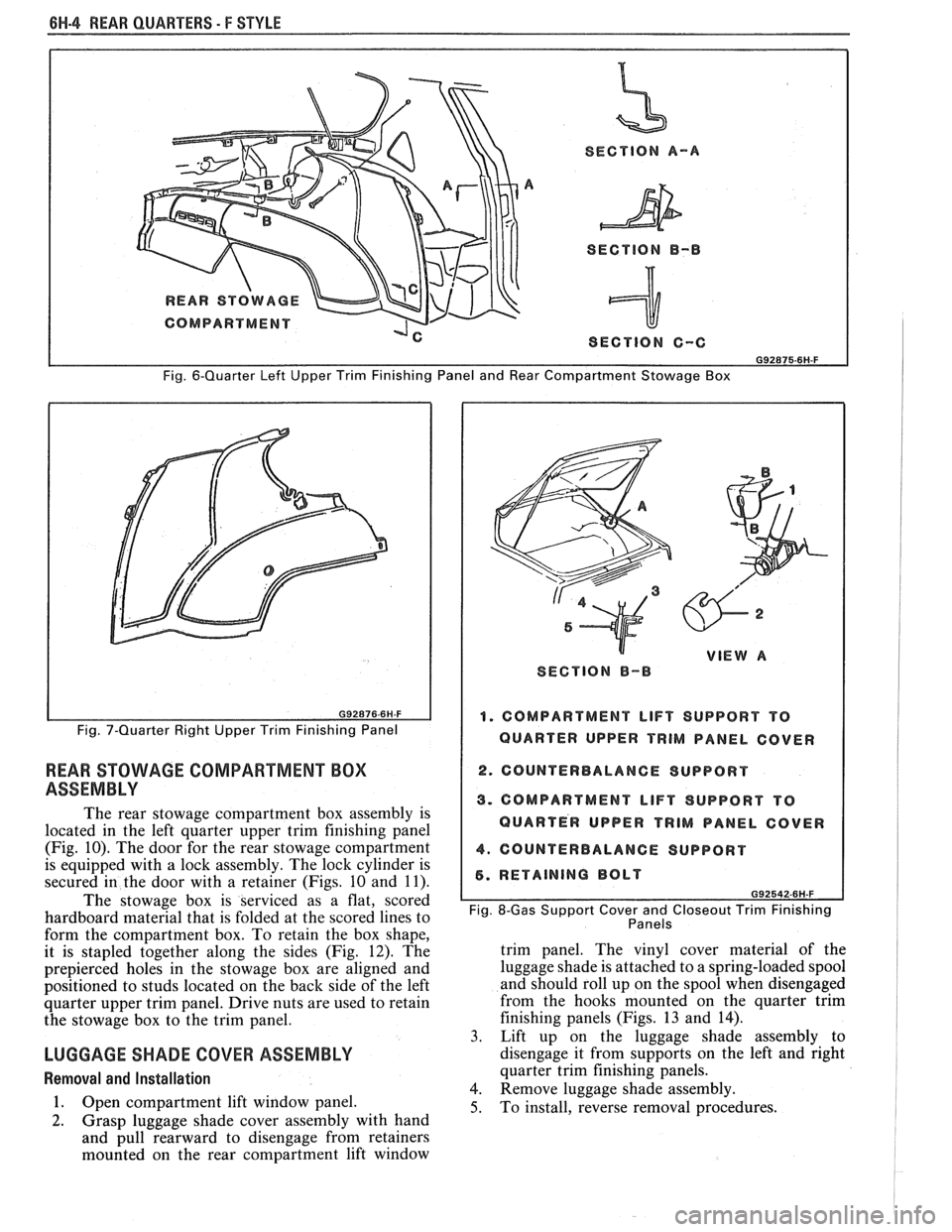
quarter trim from rear end trim panel (Fig.
6).
8. Rotate trim finishing panel downward and
inboard to disengage from gas support
attachment to body, also from rear
seatback lock
striker on the right side (Fig.
7).
9. Lift up on trim panel and remove.
10. To install, reverse removal procedures.
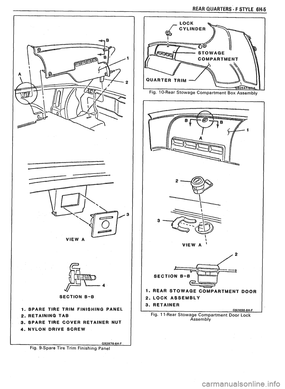
SPARE TIRE COVER TRlM FINISHING PANEL
Removal and Installation (Fig. 9)
1. Remove nylon drive screws.
SECTION 8-8
a
1. QUARTER UPPER TRIM FINISHING PANEL
2. INSERT PANEL
3. CLIP, INSERT PANEL
4. QUARTER LOWER TRIM FINISHING G~zE~~-~H-F PANEL
Fig. 4-Quarter Upper Trim Finishing Panel Insert
1. SUBWOOFER PEAKER
1 2. SCREWS
9. CONNECTOR
I 4. CONNECTOR
2. Grasp spare tire cover trim finishing panel with
hand and pull upward to disengage retaining tabs
Fig. 5 - Installing Subwoofer Speaker
from slots in rear compartment floor.
3. Remove spare tire cover.
4. To install, reverse the removal procedure.
Page 1739 of 1825
BH-4 REAR QUARTERS - F STYLE
SECTION A-A
SECTION
B-B
I SECTION C-C I
Fig. 6-Quarter Left Upper Trim Finishing Panel and Rear Compartment Stowage Box
Fig. 7-Quarter Right Upper Trim Finishing Panel
REAR STOWAGE COMPARTMENT BOX
ASSEMBLY
The rear stowage compartment box assembly is
located in the left quarter upper trim finishing panel
(Fig. 10). The door for the rear stowage compartment
is equipped with a lock assembly. The lock cylinder is
secured in the door with a retainer (Figs. 10 and 11).
The stowage box is serviced as a flat, scored
hardboard material that is folded at the scored lines to
form the compartment box. To retain the box shape,
it is stapled together along the sides (Fig. 12). The
prepierced holes in the stowage box are aligned and
positioned to studs located on the back side of the left
quarter upper trim panel. Drive nuts are used to retain
the stowage box to the trim panel.
LUGGAGE SHADE COVER ASSEMBLY
Removal and Installation
1. Open compartment lift window panel.
2. Grasp luggage shade cover assembly with hand
and pull rearward to disengage from retainers
mounted on the rear compartment lift window
W VIEW A
SECTION 8-B
1. COMPARTMENT LIFT SUPPORT TO
QUARTER UPPER
TRIM PANEL COVER
2. COUNTERBALANCE SUPPORT I
3. COMPARTMENT LIFT SUPPORT TO
QUARTER UPPER
TRIM PANEL COVER
4. COUNTERBALANCE SUPPORT I
5. RETAINING BOLT
Fig. 8-Gas Support Cover and Closeout Trim Finishing
Panels
trim panel. The vinyl cover material of the
luggage shade is attached to a spring-loaded spool
and should roll up on the spool when disengaged
from the hooks mounted on the quarter trim
finishing panels (Figs. 13 and
14).
3. Lift up on the luggage shade assembly to
disengage it from supports on the left and right
quarter trim finishing panels.
4. Remove luggage shade assembly.
5. To install, reverse removal procedures.
Page 1740 of 1825
VlEW A
I
SECTION B-B
I 1. SPARE TlRE TRIM FINISHING PANEL
2. RETAINING TAB
3. SPARE TlRE COVER RETAINER NUT
4. NYLON DRIVE SCREW
REAR QUARTERS - F STYLE 6W-5
COMPART MENT
UARTER TRIM
I VlEW A ' I
I. REAR STOWAGE COMPARTMENT DOOR
2. LOCK ASSEMBLY
Fig. 1 I-Rear Stowage Compartment Door Lock
Assembly
Fig. 9-Spare Tire Trim Finishing Panel