PONTIAC FIERO 1988 Service Repair Manual
Manufacturer: PONTIAC, Model Year: 1988, Model line: FIERO, Model: PONTIAC FIERO 1988Pages: 1825, PDF Size: 99.44 MB
Page 1711 of 1825
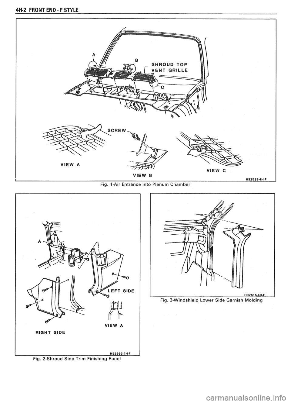
4H-2 FRONT END - F STYLE
Fig. I-Air Entrance into Plenum Chamber
Fig. 3-Windshield Lower Side Garnish Molding
Fig. 2-Shroud Side Trim Finishing Panel
Page 1712 of 1825
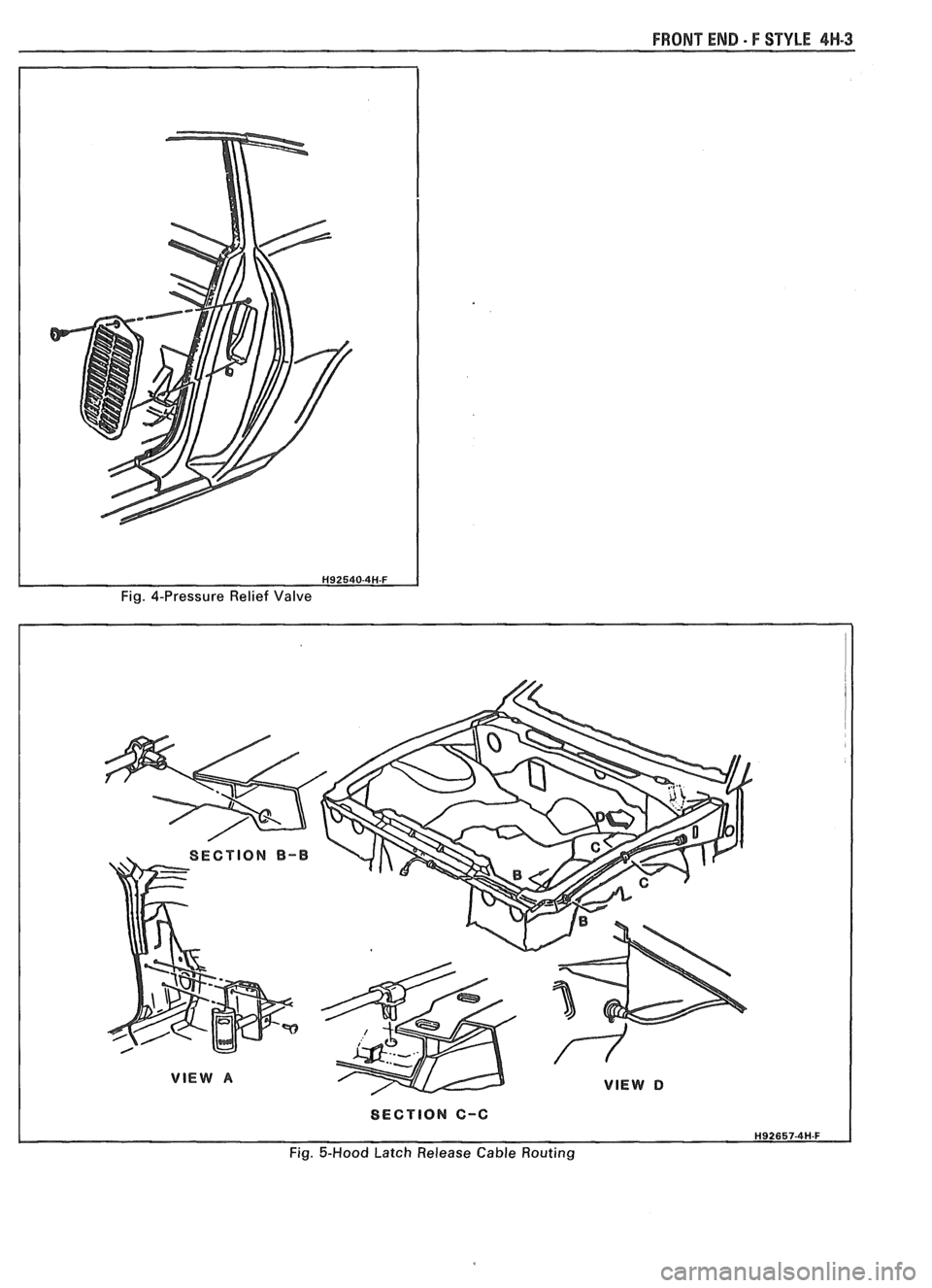
FRONT END - F STYLE 4W-3
Fig. 4-Pressure Relief Valve
I SECTION C-C I
Fig. 5-Hood Latch Release Cable Routing
Page 1713 of 1825

Page 1714 of 1825
DOORS - F STYLE 5H-1
SEC"610N 5H
DOORS
NOTICE: The anit-theft label found on some major sheet metal, engines, and transmissions must be masked
prior to painting, rustproofing, undercoating, etc. The mask
must be removed following the above operations.
Failure to keep the label clean and readable may result in liability for violation of Federal Vehicle Theft Prevention
Standard, and subject the vehicle owner to possible suspicion that the part was stolen.
Door Trim
...................................................... 5H- 1
Armrest and Pull Handle .......................... 5H- 1
Mirror Remote Controls/Bezel ................... 5H- 1
Inside Handles and Cover Plates ................ 5H- 1
Lock Knob .................................... .... ........... 5H-2
Trim Panel Assemblies .............................. 5H-2
Doors ............................................................ 5H-3
Door Weatherstrip ....................................... 5H-4
Side Roof Rail Weatherstrip ....................... 5H-4
Window Belt Sealing Strips ......................... 5H-6
Insulator Pads - Optional ............................ 5H-6
Inner Panel Water Deflectors ...................... 5H-6
Door Hinge System .................................. .... 5H-7
Door Side Hinge Strap ............................... 5H-8
Body Side Hinge Strap ................................ 5H- 10
Door Window ..................... .. ................... 5H- 10
Window Sash Channel ................................. 5H- 1 1
Window Regulator and Motor .................... 5H- 1 1
Filler Assembly (at Belt) ......................... ... . 5H- 13
Up Stop ............................ .. ...................... 5H- 14
Rear Guide Channel .................................... 5H- 15
DOOR SECnONS
This section of the manual contains the service
operations necessary for the removal, installation,
adjustment and sealing of door assemblies and
individual hardware and trim components. It is divided
into three subsections:
1. DOOR TRIM
- removal and installation
procedures for all door trim items.
2. DOORS - including hinges, door and side roof
rail weatherstrip and all lock system components.
3. EXTERIOR MOLDINGS - removal and
installation of exterior door moldings. Standard Mirror
......................................... 5H- 15
........................... Remote
Control Mirrors 5H- 15
Power-Operated Outside Mirror ................. 5H-16
Spring Clips .................................................. 5H- 16
Connecting Rods and Locking Rods .......... 5H-16
Inside Remote Handle ................................ 5H- 16
......................................... Outside Handle 5H- 16
............................. Lock Cylinder Assembly 5H- 17
...................................... Door Lock Striker 5H- 17
....................................... Door Wedge Plate 5H- 18
....................................... Door Jamb Switch 5H- 19
........................ Door Hardware Lubrication 5H- 19
Hardware Attachment Thread
.................................................. Locking 5H- 19
................................... Door Lock Assembly 5H- 19
............................ Power Door Lock System 5H-20
........................ Power Door Lock Actuator 5H-20
............. .................................... Bell Crank ... 5H-20
.......................................... Exterior Moldings 5H-20
.......................................... Spoiler on Door 5H-21
.......................................... Spoiler on Body 5H-2 1
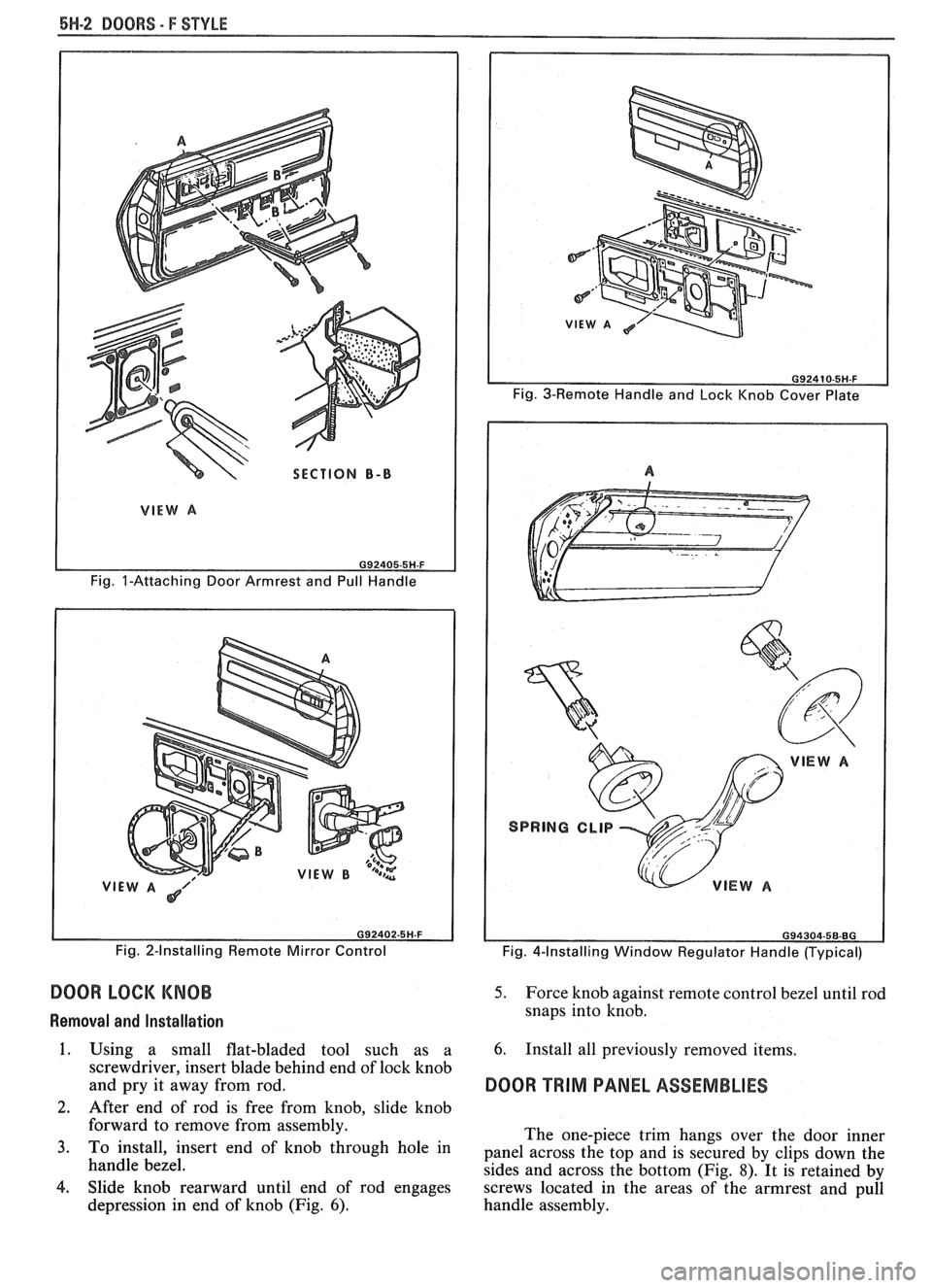
DOOR OUTSIDE MIRROR REMOTE CONTROLS
AND BEZEL
On styles with remote control door outside
mirror, the remote control mirror cable must be
disengaged from the bezel on the door trim panel to
permit trim panel removal. To disengage the remote
cable from the door trim panel, refer to Figure
2.
DOOR INSIDE HANDLES AND COVER PLATES
Door inside handles are retained by either rivets
or spring clips (Fig.
4). On styles equipped with rivet
retained handles, the rivets are covered by a screw
retained cover plate that can be removed as shown in
Figure
3.
DOOR TRIM Removal and Installation
DOOR ARMREST AND PULL HANDLE 1.
ASSEMBLIES
The armrest and pull handle is a one-piece
assembly and is secured to the door inner panel with
screws after door trim panel is installed (Fig. 1). Clips hidden
by window regulator handles (Fig,
4) can be disengaged by depressing door trim
assembly enough to permit inserting tool J-9886
or equivalent between handle and trim panel or
plastic bearing plate (Fig.
5). Then, with tool in
same plane as inside handle, push tool as
indicated to disengage clip. Pull handle inboard
The removal of the door trim panel on styles with to
remove from
s$n>le. -
door armrest and pull handle assemblies requires 2. To install window regulator handles, engage
removal of screws inserted through the assembly's base retaining clip on handle. Position handle at same
into the armrest hanger plate and removal of the screw angle as opposite side handle and press handle
at the top of the pull handle section.
outboard until clip engages regulator spindle.
Page 1715 of 1825
6H-2 DOORS - F STYLE
SECTION B-B
Fig. I-Attaching Door Armrest and Pull Handle
VIE Fig. 2-Installing Remote Mirror Control
DOOR LOCK KNOB
Removal and Installation
1. Using a small flat-bladed tool such as a
screwdriver, insert blade behind end of lock knob
and pry it away from rod.
2. After end of rod is free from knob. slide knob
Fig. 3-Remote Handle and Lock Knob Cover Plate
Fig. 4-Installing Window Regulator Handle (Typical)
5. Force knob against remote control bezel until rod
snaps into knob.
6. Install all previously removed items.
DOOR TRIM PANEL ASSEMBLIES
forward to remove from assembly.
The one-piece trim hangs over the door inner
3. To install, insert end of knob through hole in panel across the top and is secured by clips down the
handle bezel.
sides and across the bottom (Fig.
8). It is retained by
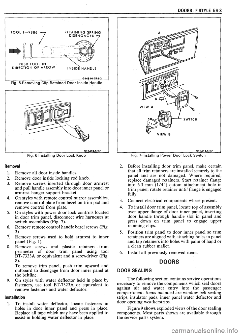
4. Slide knob rearward until end of rod engages
screws located in the areas of the armrest and pull
depression in end of knob (Fig.
6). handle assembly.
Page 1716 of 1825
BOORS - F STYLE 5H-3
I
J-9886
7
RETAINING SPRING
DISENGAGED 7
Fig. 5-Removing Clip Retained Door Inside Handle
Fig. 6-Installing Door Lock Knob
Removal
1. Remove all door inside handles.
2. Remove door inside locking rod knob.
3. Remove screws inserted through door armrest
and pull handle assembly into door inner panel or
armrest hanger support bracket.
4. On styles with remote control mirror assemblies,
remove control plate from bezel on trim pad and
remove control from plate.
5. On styles with power door lock controls located
in door trim panel, disconnect wire harnesses at
switch assemblies (Fig. 7).
6. Remove remote control handle bezel screws (Fig.
3)
7. Remove
screws used to hold armrest to inner
panel (Fig.
1).
8. Remove screws and plastic retainers from
perimeter of door trim panel using tool
BT-73238 or equivalent and a screwdriver (Fig.
8).
To remove trim panel, push trim upward and
outboard to disengage from door inner panel at
the beltline.
9. On styles with water deflector held in place by
fasteners, use tool BT-7323A or equivalent to
remove fasteners and water deflector.
Installation
1. To install water deflector, locate fasteners in
holes in door inner panel and press in place.
Replace all tape which may have been applied to
assist in holding water deflector in place.
Fig. 7-Installing Power Door Lock Switch
2. Before installing door trim panel, make certain
that all trim retainers are installed securely to the
panel and are not damaged. Where required,
replace damaged retainers. Start retainer Range
into 6.3 mm
(1/4") cutout attachment hole in
trim panel, rotate retainer until flange is engaged
fully.
3. Connect electrical components where present.
4. To install door trim panel, locate top of assembly
over upper flange of door inner panel, inserting
door handle through handle slot in panel and
press down on trim panel to engage upper
retaining clips.
5. Position trim panel to door inner panel so trim
retainers are aligned with attaching holes in panel
and tap retainers into holes with palm of hand or
a clean rubber mallet.
6. Install all previously removed items.
BOORS
DOOR SEALING
The following section contains service operations
necessary to remove the components which seal doors
against air and water entry into the passenger
compartment. Items included are window belt sealing
strips, insulator pads, inner panel water deflector and
door opening weatherstrips.
Figure
9 shows exploded views of the door sealing
components. Most parts shown are available through
the service parts system.
Page 1717 of 1825
5H.4 DOORS - F STYLE
SECTION A-A SECTION B-B
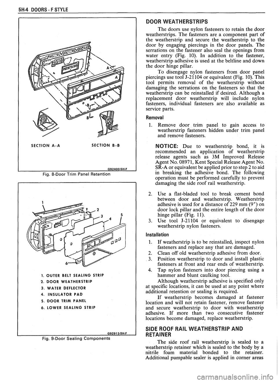
Fig. 8-Door Trim Panel Retention
1. OUTER BELT SEALING STRIP
2. DOOR WEATHERSTRIP
3. WATER DEFLECTOR
4. INSULATOR PAD
5. DOOR TRIM PANEL
6. LOWER SEALING STRIP
Fig. 9-Door Sealing Components
DOOR WEATHERSTRIPS
The doors use nylon fasteners to retain the door
weatherstrips. The fasteners are a component part of
the weatherstrip and secure the weatherstrip to the
door by engaging piercings in the door panels. The
serrations on the fastener also seal the openings from
water entry (Fig. 10). In addition to the fastener,
weatherstrip adhesive is used at the
beltline and down
the door hinge pillar.
To disengage nylon fasteners from door panel
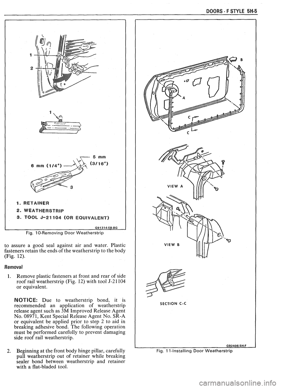
piercings use tool J-21104 or equivalent (Fig. 10). This
tool permits removal of the weatherstrip without
damaging the serrations on the fasteners so that the
weatherstrip can be reinstalled if desired. Although a
replacement door weatherstrip will include nylon
fasteners, individual fasteners are also available as
service parts.
Removal
1. Remove door trim panel to gain access to
weatherstrip fasteners hidden under trim panel
and remove fasteners.
NOTICE: Due to weatherstrip bond, it is
recommended an application of weatherstrip
release agents such as
3M Improved Release
Agent No. 08971, Kent Special Release Agent No.
SR-A or equivalent be applied prior to step 2 to aid
in breaking the adhesive bond. The following
operation must be performed carefully to prevent
damaging the side roof rail weatherstrip.
2. Use a flat-bladed tool to break cement bond
between door and weatherstrip. Weatherstrip
adhesive is used for a distance of 229 mm (9") on
door lock pillar and the entire length of the door
hinge pillar (Fig. 11).
3. Use tool J-21104 or equivalent to disengage
weatherstrip nylon fasteners.
Installation I 1
1. If weatherstrip is to be reinstalled, inspect nylon
fasteners and replace any that are damaged.
2. Clean
off old weatherstrip adhesive from door.
3. Position weatherstrip to door and install plastic
fasteners at front and rear ends of weatherstrip.
4. Tap
nylon fasteners into door piercing using a
hammer and blunt caulking tool.
Although weatherstrip adhesive is specified only
at specific locations, it can be used at any point where
additional retention or sealing is required.
If weatherstrip becomes damaged at fastener
location and will not retain fastener, remove fastener
and secure weatherstrip to door with weatherstrip
adhesive. If more than two consecutive fastener
locations become damaged, replace weatherstrip.
SIDE ROOF RAIL WEATHERSTRIP AND
RETAINER
The side roof rail weatherstrip is sealed to a
weatherstrip retainer which is sealed to the body by a
nitrile foam material bonded to the retainer.
Additional
pumpable sealer is applied in corner areas
Page 1718 of 1825
DOORS - F STYLE 5H-5
1. RETAINER
2. WEATHEWSTRIP
3. TOOL 5-24 184 (OR EQUIVALENT)
Fig. 10-Removing Door Weatherstrip
to assure a good seal against air and water. Plastic
fasteners retain the ends of the weatherstrip to the body
(Fig. 12).
Removal I
1. Remove plastic fasteners at front and rear of side
roof rail weatherstrip (Fig.
12) with tool 5-21 104
or equivalent.
NOTICE: Due to weatherstrip bond, it is
recommended an application of weatherstrip
release agent such as
3M Improved Release Agent
No. 08971,
Kent Special Release Agent No. SR-A
or equivalent be applied prior to step
2 to aid in
breaking adhesive bond. The following operation
must be performed carefully to prevent damaging
side roof rail weatherstrip.
2. Beginning
at the front body hinge pillar, carefully
h
pull weatherstrip out of retainer while breaking
sealer bond between weatherstrip and retainer
with a flat-bladed tool.
SECTION C-C
Fig. 1 I-Installing Door Weatherstrip
Page 1719 of 1825
5W-8 BOORS - F STYLE
3. With weatherstrip removed, screws securing
weatherstrip retainer to side roof rail are exposed.
Mark position of retainer on rail or pillar and
remove screws from retainer.
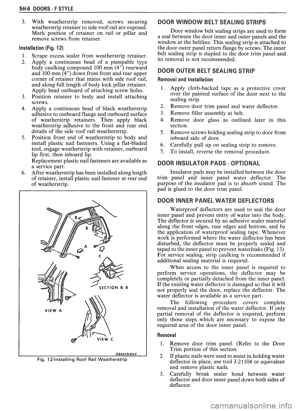
Installation (Fig. 1 2)
1.
Scrape excess sealer from weatherstrip retainer.
2. Apply a continuous bead of a
pumpable type
body caulking compound 100 mm (4") rearward
and 100 mm (4") down from front and rear upper
corner of retainer that mates with side roof rail,
and along full length of body lock pillar retainer.
Apply bead outboard of attaching screw holes.
3. Position retainer to body and install attaching
screws.
4. Apply a continuous bead of black weatherstrip
adhesive to outboard flange and outboard surface
of weatherstrip retainers. Then apply black
weatherstrip adhesive to the front and rear end
details of the side roof rail weatherstrip.
5. Position front end of weatherstrip to body and
install plastic nail fasteners. Using a flat-bladed
tool, engage weatherstrip with retainer, outboard
lip first, then inboard lip.
Replacement plastic nail fasteners are available as
a service part.
6. After weatherstrip has been installed along length
of retainer, install plastic nail fastener at rear end
of weatherstrip.
SECTION B-B
Fig. 12-Installing Roof Rail Weatherstrip
DOOR WINDOW BELT SEALING STRIPS
Door window belt sealing strips are used to form
a seal between the door inner and outer panels and the
window at the beltline. This sealing strip is attached to
the door outer panel return flange by screws. The inner
belt sealing strip is stapled to the door trim panel and
its removal is not recommended.
DOOR OUER BELT SEALING STRIP
Removal and Installation
1.
Apply cloth-backed tape as a protective cover
over the painted surface of the door next to the
sealing strip.
2. Remove door trim panel and water deflector.
3. Remove filler assembly at belt.
4. Remove door glass as outlined later in this
section.
5. Remove screws holding sealing strip to door from
inboard side of door.
6. Carefully pull up on sealing strip to remove.
7. To install, reverse the removal procedure.
DOOR INSULAWR PADS - OPTIONAL
Insulator pads may be installed between the door
trim panel and inner panel water deflector. The
purpose of the insulator pad is to absorb sound. The
pad is glued to the door trim panel.
DOOR INNER PANEL WATER DEFLECTORS
Waterproof deflectors are used to seal the door
inner panel and prevent entry of water into the body.
The deflector is secured by an adhesive sealer material
along the front edges, rear edges and bottom, and by
the application of waterproof sealing tape. Whenever
work is performed where the water deflector has been
disturbed, the deflector must be properly sealed and
taped to the inner panel to prevent waterleaks (Fig. 13).
For service sealing, strip caulking is recommended if
additional sealing material
is required.
When access to the inner panel is required to
perform service operations, the deflector may be
completely or partially detached from the inner panel.
If the existing water deflector is damaged so that it will
not properly seal the door, replace the deflector. The
water deflector is available as a service part.
The following procedure covers complete
removal and installation of the water deflector. If only
partial removal of the deflector is required, perform
only those steps which are necessary to expose the
required area of the door inner panel.
Removal
1. Remove door trim panel. (Refer to the Door
Trim portion of this section.
2. If plastic nails were used to assist in holding water
deflector in place, use tool J-21104 or equivalent
and remove plastic nails.
3. Carefully break sealer bond between water
deflector and door inner panel down both sides of
deflector.
Page 1720 of 1825
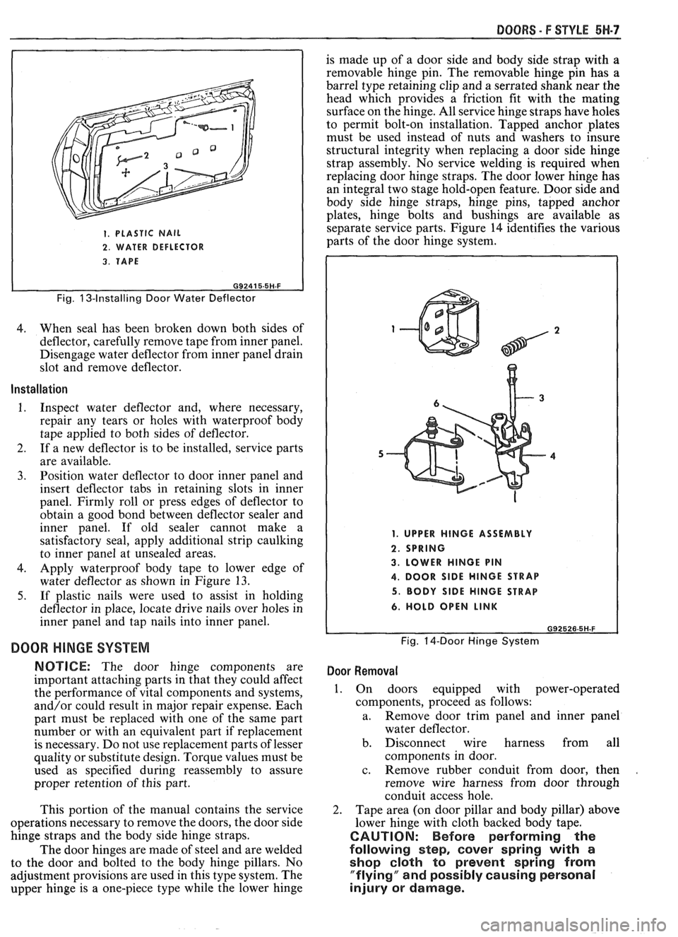
1. PLASTIC NAIL
2. WATER DEFLECTOR
DOORS - F STYLE 5H-7
is made up of a door side and body side strap with a
removable hinge pin. The removable hinge pin has
a
barrel type retaining clip and a serrated shank near the
head which provides a friction fit with the mating
surface on the hinge. All service hinge straps have holes
to permit bolt-on installation. Tapped anchor plates
must be used instead of nuts and washers to insure
structural integrity when replacing a door side hinge
strap assembly. No service welding is required when
replacing door hinge straps. The door lower hinge has
an integral two stage hold-open feature. Door side and
body side hinge straps, hinge pins, tapped anchor
plates, hinge bolts and bushings are available as
separate service parts. Figure 14 identifies the various
parts of the door hinge system.
3. TAPE
I
Fig. 13-Installing Door Water Deflector
4. When seal has been broken down both sides of
deflector, carefully remove tape from inner panel.
Disengage water deflector from inner panel drain
slot and remove deflector.
Installation
1. Inspect water deflector and, where necessary,
repair any tears or holes with waterproof body
tape applied to both sides of deflector.
2. If a new deflector is to be installed, service parts
are available.
3. Position water deflector to door inner panel and
insert deflector tabs in retaining slots in inner
panel. Firmly roll or press edges of deflector to
obtain a good bond between deflector sealer and
inner panel. If old sealer cannot make a
satisfactory seal, apply additional strip caulking
to inner panel at unsealed areas.
4. Apply waterproof body tape to lower edge of
water deflector as shown in Figure
13.
5. If plastic nails were used to assist in holding
deflector in place, locate drive nails over holes in
inner panel and tap nails into inner panel.
DOOR HINGE SYSTEM
NOTICE: The door hinge components are
important attaching parts in that they could affect
the performance of vital components and systems,
and/or could result in major repair expense. Each
part must be replaced with one of the same part
number or with an equivalent part if replacement
is necessary. Do not use replacement parts of lesser
quality or substitute design. Torque values must be
used as specified during reassembly to assure
proper retention of this part.
This portion of the manual contains the service
operations necessary to remove the doors, the door side
hinge straps and the body side hinge straps.
The door hinges are made of steel and are welded
to the door and bolted to the body hinge pillars. No
adjustment provisions are used in this type system. The
upper hinge is a one-piece type while the lower hinge
1. UPPER HINGE ASSEMBLY
2. SPRING
3. LOWER HINGE PIN
4. DOOR SlDE HINGE STRAP
5. BODY SlDE HINGE STRAP
6. HOLD OPEN LINK
Fig. 14-Door Hinge System
Door Removal
1. On doors equipped with power-operated
components, proceed as follows:
a. Remove
door trim panel and inner panel
water deflector.
b. Disconnect wire harness from all
components in door.
c. Remove rubber conduit from door, then
.
remove wire harness from door through
conduit access hole.
2. Tape area (on door pillar and body pillar) above
lower hinge with cloth backed body tape.
CAUTION: Before performing the
following step,
cover spring with a
shop cloth to prevent spring from
"flying" and possibly causing personal
injury or damage.