PONTIAC FIERO 1988 Service Repair Manual
Manufacturer: PONTIAC, Model Year: 1988, Model line: FIERO, Model: PONTIAC FIERO 1988Pages: 1825, PDF Size: 99.44 MB
Page 1691 of 1825
1 W-10 GENERAL INFORMATION - F STYLE
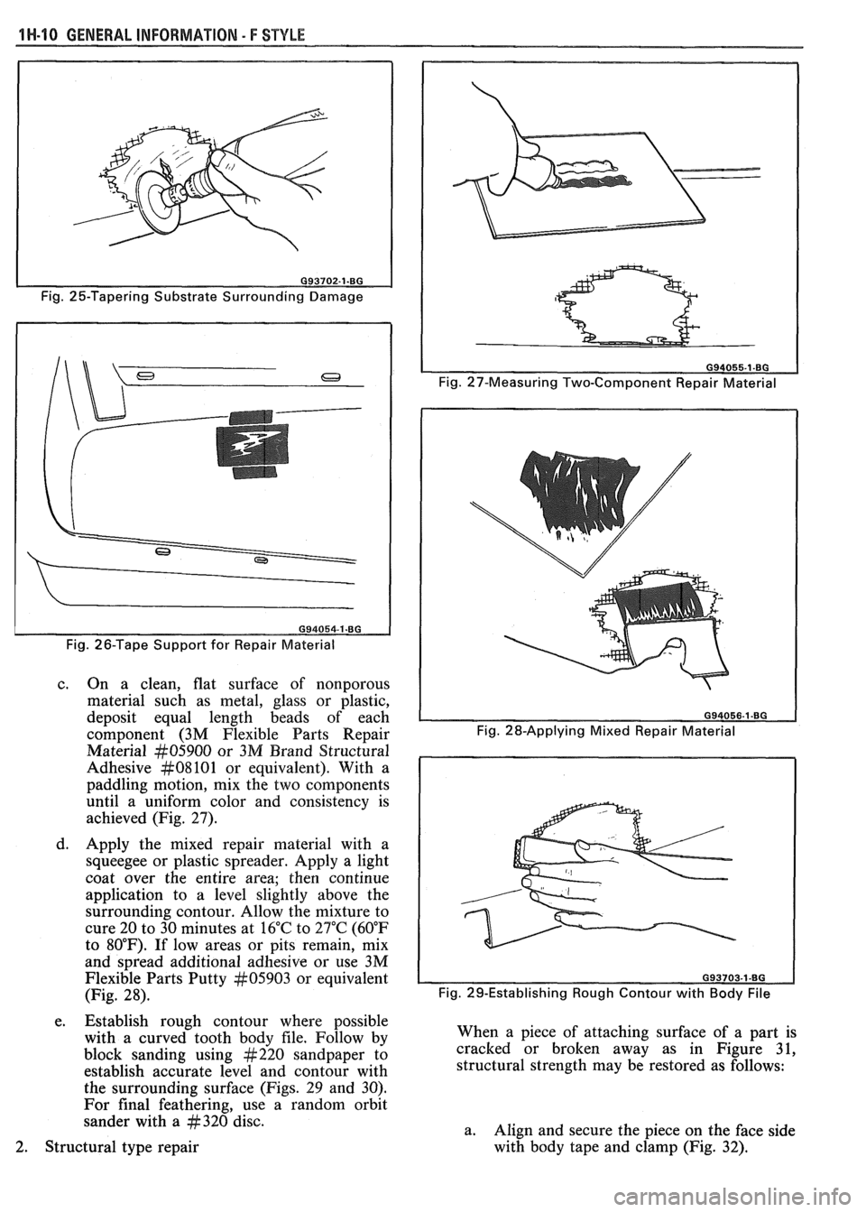
Fig. 25-Tapering Substrate Surrounding Damage
Fig. 26-Tape Support for Repair Material
c. On a clean, flat surface of nonporous
material such as metal, glass or plastic,
deposit equal length beads of each
component (3M Flexible Parts Repair
Material
#05900 or 3M Brand Structural
Adhesive
#08101 or equivalent). With a
paddling motion, mix the two components
until a uniform color and consistency is
achieved (Fig. 27).
d. Apply the mixed repair material with a
squeegee or plastic spreader. Apply a light
coat over the entire area; then continue
application to a level slightly above the
surrounding contour. Allow the mixture to
cure 20 to 30 minutes at 16°C to 27°C (60°F
to 80°F). If low areas or pits remain, mix
and spread additional adhesive or use 3M
Flexible Parts Putty
#05903 or equivalent
(Fig. 28).
e. Establish rough contour where possible
with a curved tooth body file. Follow by
block sanding using
#220 sandpaper to
establish accurate level and contour with
the surrounding surface (Figs. 29 and 30).
For final feathering, use a random orbit
sander with a
#320 disc.
Fig. 27-Measuring Two-Component Repair Material
Fig. 29-Establishing Rough Contour with
Body File
When a piece of attaching surface of a part is
cracked or broken away as in Figure 31,
structural strength may be restored as follows:
a. Align and secure the piece on the face side
with body tape and clamp (Fig.
32). 2. Structural type repair
Page 1692 of 1825
GENERAL INFORMATION - F STYLE 1 N-1 l
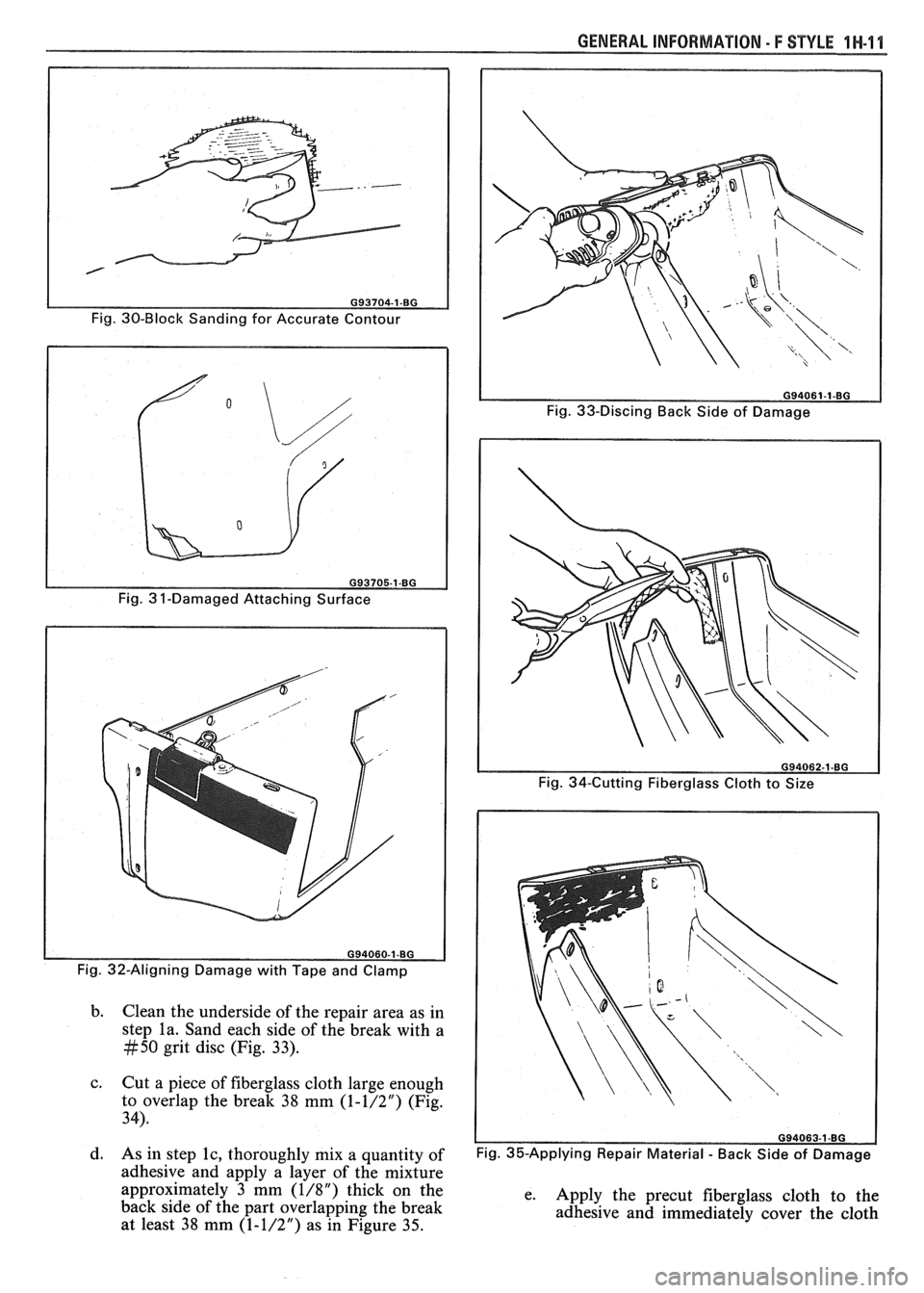
Fig. 30-Block Sanding for Accurate Contour
Fig. 33-Discing Back Side of Damage
Fig. 32-Aligning Damage with Tape and Clamp
b. Clean the underside of the repair area as in
step la. Sand each side of the break with a
#50 grit disc (Fig. 33).
c. Cut a piece of fiberglass cloth large enough
to overlap the break 38 mm
(1-1/27 (Fig.
34).
d. As in step lc, thoroughly mix a quantity of
adhesive and apply a layer of the mixture
approximately 3 mm
(1/8") thick on the
back side of the part overlapping the break
at least 38 mm
(1-1/2") as in Figure 35.
Fig. 35-Applying Repair Material - Back Side of Damage
e.
Apply the precut fiberglass cloth to the
adhesive and immediately cover the cloth
Page 1693 of 1825
1 H-12 GENERAL INFORMATION - F STYLE
with additional adhesive in sufficient
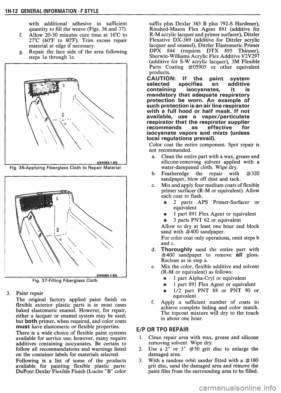
quantity to fill the weave (Figs. 36 and 37).
f. Allow
20-30 minutes cure time at 16°C to
27°C (60°F to 80°F). Trim excess repair
material at edge if necessary.
g. Repair
the face side of the area following
steps la through le.
Fig. 36-Applying Fiberglass Cloth to Repair Material
Fig. 37-Filling Fiberglass Cloth
3. Paint repair
The original factory applied paint finish on
flexible exterior plastic parts is in most cases
baked elastomeric enamel. However, for repair, either a lacquer or enamel system may be used;
but
both primer, when required, and color coats
must have elastomeric or flexible properties.
There is a wide choice of flexible paint systems
available for service use; however, many require
additives containing isocyanates. Be certain to
follow all recommendations and warnings listed
on the container labels for materials selected.
Following is a list of some of the products
available for painting flexible plastic parts:
DuPont Dexlar Flexible Finish (Lucite " B" color suffix
plus Dexlar 365 B plus 792-S Hardener),
Rinshed-Mason Flex Agent 891 (additive for
R-M acrylic lacquer and primer surfacer), Ditzler
Flexative DX-369 (additive for Ditzler acrylic
lacquer and enamel), Ditzler Elastomeric Primer
DPX 844 (requires DTX 895 Thinner),
Sherwin-Williams Acrylic Flex Additive
V2V297
(additive for S-W acrylic lacquer), 3M Flexible
Parts Coating
kt05905 or other equivalent
products.
CAUTION: If the paint system
selected specifies an additive
containing isocyanates, it is
mandatory that adequate respiratory
protection be worn. An example of
such protection is an air line respirator
with a full hood or half mask.
If not
available, use a
vapor/particulate
respirator that the respirator supplier
recommends as effective for
isocyanate vapors and mists (unless
local regulations prevail).
Color coat the entire component. Spot repair is
not recommended.
a. Clean the entire part with a wax, grease and
silicone-removing solvent applied with a
water-dampened cloth. Wipe dry.
b. Featheredge the repair with
#320
sandpaper, blow off dust and tack.
c. Mix and apply four medium coats of flexible
primer surfacer (R-M or equivalent). Allow
each coat to flash.
o 2 parts APS Primer-Surfacer or
equivalent
s 1 part 891 Flex Agent or equivalent
o 3 parts PNT 62 or equivalent
Allow to dry at least one hour and block
sand with
#400 sandpaper.
For color coat only operations, omit steps
b
and c.
d.
Thoroughly sand the entire part with
#400 sandpaper to remove all gloss.
Reclean as in step a.
e. Mix the color, flexible additive and solvent
(R-M or equivalent) as follows:
e 1 part Alpha-Cry1 or equivalent
e 1 part 891 Flex Agent or equivalent
o 1/2 part PNT 88 or PNT 90 or
equivalent
f. Apply a sufficient number of coats to
achieve complete hiding and color match.
The topcoat mixture will dry to the touch
in about one hour.
E/P OR TPO REPAIR
1. Clean repair area with wax, grease and silicone
removing solvent. Wipe dry.
2. Use
a 2" or 3" #50 grit disc to enlarge the
damaged area.
3. With a random
orbit sander fitted with a
# 180
grit disc, sand the damaged area and remove
the
paint film from the surrounding area to be filled.
Page 1694 of 1825
GENERAL INFORMATION 5 F STYLE 1H-13
4. Prime entire area with 3M Polyolefin Adhesion
Promoter Part
kt05907 or equivalent before
filling with 3M Flexible Parts Repair Material
kt05900 or equivalent.
5. Shape repair material with curved body tooth file.
Then block sand with
#220 grit disc and final
featheredge with
#320 grit disc.
6. If low areas or pits remain, first reapply 3M
Polyolefin Adhesion Promoter or equivalent,
then mix and spread additional repair material.
Painting Flexible Parts - E/P or TPO
When painting flexible plastic exterior parts
identified as E/P or TPO, a polypropylene primer
must be used. Follow manufacturer's label
instructions.
METAL REPLACEMENWARTS
FINISHING
Metal service replacement parts (or assemblies)
are painted with a high-bake factory primer. For
proper adhesion of color coats in service, the following
refinish steps are necessary.
1. Clean part with a wax and grease-removing
solvent such as Prep-sol, Pre-Kleano,
Sher-Will-Clean, Acryli-Clean or equivalent.
2. Scuff-sand panel lightly with wet or dry no. 400
sandpaper and water. Avoid cut-throughs.
Reclean part. Apply sealer to entire part.
3. If factory primer coat was cut through, apply
metal conditioner to exposed bare metal. Follow
label directions.
4. Apply primer-surfacer to entire part; allow to dry
thoroughly before sanding. Follow label
directions for drying time.
5. Sand primer-surfacer using wet or dry no. 400
sandpaper and water. Do not sand sealer.
6. Reclean part.
7. Apply color coats to parts.
8. Follow label directions for drying time before
compounding.
9. Compound part by hand or with power
equipment.
10. Nonsealing polish may
be applied after rub-out if
desired. Waxes, however, should
not be applied
until the paint finish has aged at least two
months.
Prior to replacing exterior body parts or
assemblies, check condition of paint on all covered or
hidden interior surfaces.
If rust scale is found in these
areas, proceed as follows:
1. Remove rust with suitable wire brush, abrasive or
liquid rust removing agent. Follow label
directions.
2. If necessary, wash with detergent, rinse and dry.
3. Apply a heavy coating of anticorrosion
compound to all cleaned hidden surfaces before
installing exterior body parts. Also, apply
anticorrosion compound to all inner surfaces of
exterior body parts being installed.
INTERIOR PLASTBC TRIk7 PARTS
FINISHING
Paintable plastic interior trim components can be
divided into three general types:
Polypropylene Plastic
@ ABS Plastic
e Vinyl Plastic
It is important for a painter to be able to identify
each plastic in order to paint it satisfactorily. Painting
of complete soft seat cushion and
seatback trim cover
assemblies of vinyl construction is not approved by the
factory. Excluding the soft seat cushion and seat back
trim cover assemblies, the plastic used most widely on
the interior of bodies is polypropylene.
The purpose of the following tests is to determine
the identity of a given plastic so that proper paint
procedures and materials can be used.
Pest for Polypropylene and ABS Plastic
To determine if a service part to be painted is
polypropylene or
ABS plastic, perform the following
burn test:
1. From a hidden backside portion of the part,
remove a sliver of plastic with a sharp blade.
2. While holding the sliver of plastic with tweezers
or laying it on a clean noncombustible surface,
ignite the plastic.
3. Observe the burning plastic closely:
a. Polypropylene burns with no readily visible
smoke.
b. ABS plastic burns with a readily visible
black smoke residue which hangs
temporarily in the air.
Pest for Vinyl Plastic
To determine if a part to be painted is vinyl plastic
(polyvinyl chloride), a copper wire test should be
performed as follows:
1. Heat a copper wire in a suitable flame such as
provided by a propane or equivalent torch until
the wire glows (turns red).
2. Touch the heated wire to the backside or hidden
surface of the part being
testsd in a manner so as
to retain some of the plastic on
the wire.
3. Return the wire (and retained plastic) to the
flame and observe for a green, turquoise blue
flame. A flame in this color range indicates that
the plastic being tested is vinyl.
4. If black smoke residue, which hangs temporarily
in the air, is readily visible when wire (with
retained plastic residue) is returned to the flame,
the part is made of flexible (soft)
ABS plastic
material.
PAINTING POLYPROPYLENE PLASTIC PARTS
The system for painting polypropylene parts
involves the use of a special primer. Since
polypropylene plastic is hard, it can be
color coated
after prime with conventional interior acrylic lacquer.
Page 1695 of 1825
1 H-14 GENERAL INFORMATION - F STYLE
NOTICE: Service part must be primed with a
coating of special polypropylene primer according
to factory recommendations. Failure to use the
required primer as directed will result in color coat
lifting and/or peeling problems. Use
Polypropylene Primer, part no. 1052364, or
equivalent.
1. Wash part with a solvent such as Acryli-Clean,
Pre-Kleano, Prep-Sol or equivalent. Follow label
directions.
2. Apply
a thin, wet coat of polypropylene primer
according to label directions. Wetness of primer
is determined by observing gloss reflection of
spray application in adequate lighting. Be sure
primer application includes all edges. Allow
primer to flash dry one minute minimum and ten
minutes maximum.
3. During the above flash time period (1 to 10
minutes), apply conventional interior acrylic
lacquer color as required and allow to dry before
installing part. Application of color during above
flash time range promotes best adhesion of color
coats.
PAINTING RIGID OR HARD ABS PLASTIC
PARTS
Rigid or hard ABS plastic requires no primer.
Conventional interior acrylic lacquers adhere
satisfactorily to hard ABS plastics.
1. Wash part with a solvent such as ~cr~li-clean,
Pre-Kleano, Prep-Sol or equivalent.
2. Apply conventional interior acrylic lacquer color
according to trim combination (see paint supplier
color chart for trim and color code). Apply only
enough color for proper hiding to avoid washout
of "grain" effect.
3. Allow to dry following label directions and then
install part.
PAINTING VINYL AND FLEXIBLE (SOFT) ABS
PLASTIC PARTS
The outer cover material of flexible instrument
panel cover assemblies is made mostly of ABS plastic
modified with PVC or vinyl. The same is true of many
padded door trim assemblies. The soft cushion padding
under
ABS covers is urethane foam plastic.
The most widely used flexible vinyls (polyvinyl
chloride) are coated fabrics as used in seat trim, some
door trim assemblies, headlinings and sunshades. Most
head restraints are covered with flexible vinyls.
Examples of hard vinyls are door and front
seatback
assist handles, coat hooks and exterior molding inserts. The
paint system for vinyl and flexible
ABS
plastic involves the use of interior vinyl color and a
clear vinyl top coat, No primer or primer-sealer is
required.
1. Wash part with a vinyl cleaning and preparation
solvent, such as Vinyl Prep, Vinyl Prep
Conditioner or equivalent. Wipe off cleaner while
still wet with clean, lint-free cloth.
2. As soon as the surface has been wiped dry, apply
interior vinyl color in wet coats. Allow flash time
between coats. Follow label directions. Use
proper vinyl color as shown by interior trim code
combination. Apply only enough color for proper
hiding to avoid washout of grain effect.
3. Before color flashes completely, apply one wet
double coat of vinyl clear top coat. Use top coat
with appropriate gloss level to match adjacent
similar components. The clear coat is necessary
to control the gloss requirement and to prevent
crocking (rubbing-off) of the color coat after
drying.
4. Allow to dry according to label directions before
installing part.
AVAILABILITY OF COLORS FOR PAINTING
INTERIOR PLASTIC PARTS
Interior colors are color keyed to trim code
combination numbers located on the body number
plate or service parts identification label.
Conventional interior acrylic lacquer colors are
designed for use only on hard trim parts, such as:
1. Steel parts (primer and/or sealer required on new
service parts)
2. Hard
ABS plastic (no primer necessary)
3. Hard polypropylene plastic (special primer
required)
Each major paint supplier provides an interior
color chart which identifies the stock number, color
name, gloss factor and trim code combination number
for each conventional interior color.
Vinyl interior colors are designed for soft trim
parts such as instrument panel cover assemblies, door
trim assemblies and head restraints. These colors
require a final top coat of clear vinyl. Instrument panel
covers require a nonglare final top coat. Other trim
parts require a degree of gloss to match similar
adjacent parts. Use interior vinyl colors and clear vinyl
finishes such as Ditzler Vinyl Spray Colors, American
Jetway UR-1 Vynicolor or equivalents.
SPECIAL BODY TOOLS
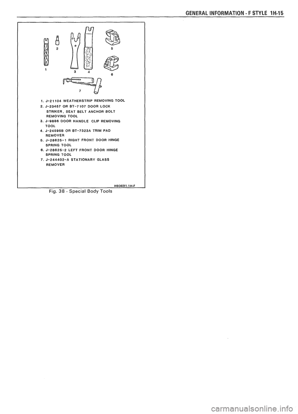
Figure 38 shows the special body tools that are
recommended as aids in servicing the various body
components. Equivalent tools may be substituted.
Page 1696 of 1825
GENERAL INFORMATION - F STYLE 1H-45
1. J-21104 WEATHERSTRIP REMOVING TOOL
2.
J-23457 OR BT-7107 DOOR LOCK
STRIKER, SEAT BELT ANCHOR BOLT
REMOVING TOOL
3. J-8888 DOOR HANDLE CLIP REMOVlNG
4. J-245BSB OR BT-73238 TRIM PAD
REMOVER
5.
J-28625-1 RIGHT FRONT DOOR HINGE
SPRING TOOL
6.
J-28625-2 LEFT FRONT DOOR HINGE
SPRING TOOL
7. J-244402-A STATIONARY GLASS
REMOVER
Fig. 38 - Special Body Tools
Page 1697 of 1825

Page 1698 of 1825
STATIONARY GLASS - F STYLE 2H.1
ONARY GLASS
Removal of Minor Scratches and
Abrasions
........................... .. ................... 2H- 1
Windshield Reveal Molding ............................ 2H-2
Stationary Glass ............................................... 2H-2
Adhesive Service Kit .................................. 2H-2
Window Removal ....................................... 2H-3
......................... Installation - Short Method 2H-3
.................. Installation - Extended Method 2H-4
................................... Waterleak Correction 2H-5
.................. Bonded Rearview Mirror Support 2H-5
.................................. Rear Window Defogger 2H-6
REMOVAL OF MINOR SCRATCHES AND
ABRASIONS
Minor glass scratches and abrasions on the
outside surface of the glass can be removed or reduced
by using the methods described in this section.
There are two basic types of auto glass: laminated
safety plate (used in all windshields) and solid
tempered safety plate (used in side and back windows).
A major concern in glass polishing is the chance
of causing double vision in areas of occupant vision.
For this reason, removal of scratches or abrasions on
a windshield in the occupant's line of vision is more
limited than in other areas. Distortion is most apt to
result when trying to remove deep scratches. Scratch
removal must be performed with care.
Tools Required:
e Low speed (600- 1300 RPM) rotary polisher (Ski1
Model No. 570 or equivalent).
Wool felt rotary-type polishing pad, about 75 mm
(3") in diameter and 50 mm (2") thick.
e Powdered cerium oxide (No. 14 Rareox or
equivalent) mixed with water as the abrasive
compound. Follow manufacturer's directions
when using any type of polishing compound.
e Wide mouth container to hold the polish.
NOTICE: Glass polishing must not be performed
on inside surface of rear window glass which has
heating elements in the glass because the heating
elements will be damaged.
1. Mix two parts of polishing compound (No. 14
Rareox or equivalent) with one part water to
obtain a creamy mixture.
2. Stir mixture now and then to maintain a creamy
texture. Powdered cerium oxide is hard to mix
with water and tends to separate.
3. Draw a circle around scratches on opposite side
of
glasS with a wax marking pencil or crayon.
Draw other lines directly behind scratches to
serve as guides in locating scratch during
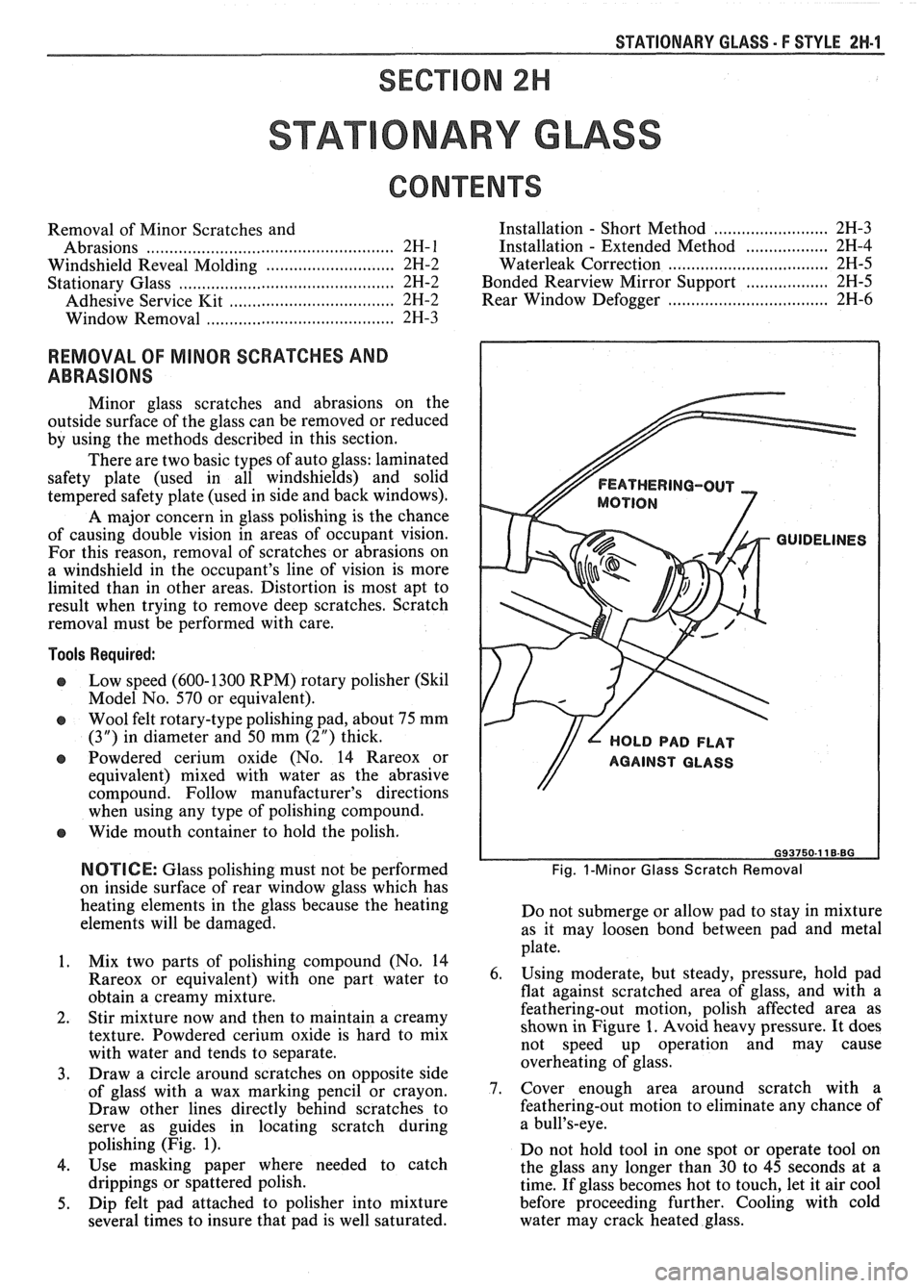
polishing (Fig. 1).
4. Use masking paper where needed to catch
drippings or spattered polish.
5. Dip felt pad attached to polisher into mixture
several times to insure that pad is well saturated.
FEATHERING-OUT
MOTION
GUIDELINES
// L HOLD PAD FLAT
Fig. I-Minor Glass Scratch Removal
Do not submerge or allow pad to stay in mixture
as it may loosen bond between pad and metal
plate.
6. Using moderate, but steady, pressure, hold pad
flat against scratched area of glass, and with a
feathering-out motion, polish affected area as
shown in Figure 1. Avoid heavy pressure. It does
not speed up operation and may cause
overheating of glass.
7. Cover enough area around scratch with a
feathering-out motion to eliminate any chance of
a bull's-eye.
Do not hold tool in one spot or operate tool on
the glass any longer than 30 to 45 seconds at a
time. If glass becomes hot to touch, let it air cool
before proceeding further. Cooling with cold
water may crack heated glass.
Page 1699 of 1825
2W-2 STATIONARY GLASS - F STYLE
8. Dip pad into mixture frequently to insure that
wheel and glass are always wet during polishing
operation. A dry pad causes too much heat to
build up.
9. After
removing scratch or abrasion, wash glass
with water and wipe body clean of any polish.
10. Clean polishing pad.
Care should be taken during polishing and
storage to keep pad free of foreign material such as dirt,
metal filings, etc.
WINDSHIELD VINYL REVEAL
MOLDINGS
Vinyl Reveal Moldings
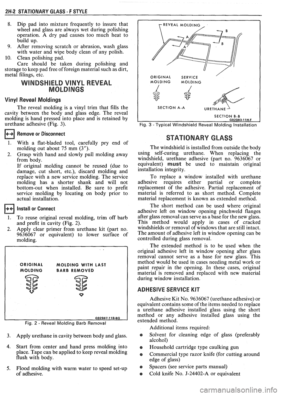
The reveal molding is a vinyl trim that fills the
cavity between the body and glass edge. The reveal
molding is hand pressed into place and is retained by
urethane adhesive (Fig. 3).
REVEAL MOLD1
ORIGINAL SERVICE /
I MOLDING MOLDING
4 6
SECTION A-A
Fig. 3 -Typical Windshield Reveal Molding Installation
Remove or Disconnect
1. With a flat-bladed tool, carefully pry end of
molding out about 75 mm (3").
2. Grasp with hand and slowly pull molding away
from body.
If original molding cannot be reused (due to
damage, cut short, etc.), discard molding and
replace with a new service molding. The service
molding has a shorter shank and will not
bottom-out when installed. Be sure to prefit
service molding by locating on body prior to
actual installation.
install or Connect
1. To reuse original reveal molding, trim off barb
and prefit in cavity (Fig. 2).
2. Apply clear primer from urethane kit (part no.
9636067 or equivalent) to lower surface of
molding.
MOLDING WITH LAST
BARB REMOVED
Fig. 2 - Reveal Molding Barb Removal
3. Apply urethane in cavity between body and glass.
4. Start from center and hand press molding into
place. Tape can be applied to keep reveal molding
flush with body.
5. Flood molding with warm water to speed set-up
of adhesive.
STATIONARY GLASS
The windshield is installed from outside the body
using self-curing urethane. When replacing the
windshield, urethane adhesive (part no. 9636067 or
equivalent)
must be used to maintain original
installation integrity.
To replace a window installed with urethane
adhesive requires either partial or complete
replacement of the adhesive. Partial replacement of
material is referred to as short method. Complete
material replacement is known as extended method.
The short method can be used where original
adhesive left on window opening pinchweld flanges
after glass removal can serve as a base for the new glass.
This method would apply in cases of cracked
windshields or removal of windows that are still intact.
The amount of adhesive left in window opening can be
controlled during glass removal.
The extended method is to be used when the
original adhesive left in window opening after glass
removal cannot serve as a base for new glass. This
method would be used in cases needing metal work or
paint repair in the opening. In these cases, original
material is removed and replaced with new material
during window installation.
ADHESIVE SERVICE KIT
Adhesive Kit No. 9636067 (urethane adhesive) or
equivalent contains some of the items needed to replace
a urethane adhesive installed glass using the short
method or any adhesive installed glass using the
extended method.
Additional items required:
o Solvent for cleaning edge of glass (preferably
alcohol)
o Household cartridge type caulking gun
o Commercial type razor knife (for cutting around
edge of glass)
e Spacers (see service parts manual)
o Cold knife No. J-24402-A or equivalent
Page 1700 of 1825
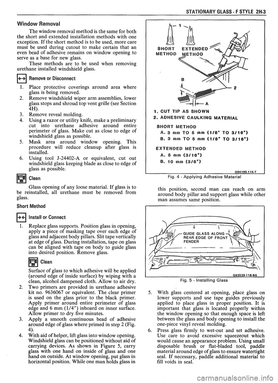
STATIONARY GLASS - F STYLE 2N-3
Window Removal
The window removal method is the same for both
the short and extended installation methods with one
exception. If the short method is to be used, more care
must be used during cutout to make certain that an
even bead of adhesive remains on window opening to
serve as a base for new glass.
These methods are to be used when removing
urethane installed windshield glass.
Remove or Disconnect
1. Place protective coverings around area where
glass is being removed.
2. Remove windshield
wi~er arm assemblies. lower
glass stops and shroud
iop vent grille (see Section
4H).
3. Remove reveal molding.
4. Using a razor or utility knife, make a preliminary
cut into urethane adhesive around entire
perimeter of glass. Make cut as close to edge of
windshield glass as possible.
5. Mask area around window opening. This
procedure will reduce cleanup after glass is
installed.
6. Using tool J-24402-A or equivalent, cut out
windshield glass keeping blade as close to edge of
glass as possible.
Clean
Glass opening of any loose material. If glass is to
be reinstalled, all urethane must be removed from
glass.
Short Method
Install or Connect
1. Replace glass supports. Position glass in opening,
apply a piece of masking tape over each edge of
glass and adjacent body pillars. Slit tape vertically
at edge of glass. During installation, tape on glass
can be aligned with tape on body to guide glass
into desired position. Remove glass.
Clean
Surface of glass to which adhesive will be applied
(around edge of inside surface) by wiping with a
clean, alcohol dampened cloth. Allow to air dry.
2. Two primers are provided in urethane adhesive
kit no. 9636067 or equivalent. The clear primer
is used on the glass prior to the black primer.
Apply primer around entire perimeter of glass
edge and 6
mrn (1/4") inboard on inner surface.
Allow primer to dry five minutes.
3. Apply a smooth continuous bead of adhesive
around edge of glass where primed in step 2 (Fig.
4). 4. With aid of helper, lift glass into window opening.
Windshield glass can be positioned without aid of
carrying devices. As shown in Figure
5, carry
glass with one hand on inside of glass and one
hand on outside. At window opening, put glass in
horizontal position. While one man holds glass in
1. CUT TIP A8 SHOWN
2. ADHESIVE CAULKING MATERIAL
SHORT METHOD
A. 3 rnm TO 5 mrn (1/8" TO 3/18")
B. 3 mrn "P 5 mm 41/8" TO 3/18")
EXTENDED
MEWHOD
A. 6 mrn (3/oen)
B. 10 rnm (318")
Fig. 4 - Applying Adhesive Material
this position, second man can reach on arm
around body pillar and support glass while other
man assumes same position.
GUIDE GLASS ALONG
WEAR EDGE OF FRON
Fig. 5 - Installing Glass
5. With glass centered at opening, place glass on
lower supports and use tape guides previously
applied to place glass in proper position. It is
important that glass is located properly within
the window opening so that enough space is left
between the glass and body opening to install the
one-piece vinyl reveal molding.
6. Press glass firmly to wet-out and set adhesive.
Use care to avoid excessive squeezeout which
would cause an appearance problem. Using small
disposable brush or flat-bladed tool, paddle
material around edge of glass to ensure watertight
seal.
If necessary, paddle additional material to
fill voids in seal.